

kaldek
-
Posts
1,317 -
Joined
-
Last visited
-
Days Won
11
Content Type
Forums
Profiles
Gallery
Blogs
Downloads
Events
Posts posted by kaldek
-
-
OK, another ride to work today and things are going downhill. I seem to have picked up a serious misfire, which is like my previous problems but worse. Also my fan isn't coming on so I think I have left the fan disconnected or the fan fuse has blown.
Agggggh.....I'm now deep in the hole and the only way to go is keep digging. I'm in too shitty a mood to go into much detail at the moment but I'll keep y'all posted.
-
Right, fuel pump tested and still providing same amount of fuel as before - 130 mils in 10 seconds (too low). No worse than before, so with the PCV and map set up I'll still ride it.
-
First big ride to and from work today, and I'm getting pre-ignition (pinging/pinking) under load.
Very interesting! I don't think the ECU is causing this, I think what it's doing is showing up the problems with the fuel pump that were not as evident before. I mean, I hadn't ridden without the Powercommander fitted for ages and without it active I've got a combination of Motad headers (probably makes it run a bit leaner), a likely leaner base fuel map in the 2006 ECU, and what based on all evidence so far is a dodgy fuel pump.
So, no huge surprises the engine pinked a bit. I've got the PCV hooked back up with a nice fat rich fuel map in it (generic tune from Dynojet). There are huge numbers in this map, like +20 all over the place so I'd say the 2006-2009 models are indeed very lean from factory.
Have to wait a week for the fuel pump to arrive now. I'll go and test my fuel flow again to see if it's gotten worse. If it's dropped down any more I'll park the bike until I replace the pump.
-
can this map be used on a PC V? Has anyone made a conversion map that will?
Yes there is a converted map in the files area: Cozye's map converted to PCV format.
-
And you can sell off your previous wiring harness and ecu to defray he cost!
Ahh...maybe not! I had to cut a few connectors off the old harness for the indicators and speed sensor. Suppose I could sell the 2002 ECU, but I'd need to liberate myself of one of my keys, but since I have three sets of keys I could do that!
Wonder what the market is like for ECUs. Probably not huge (says the guy who just bought an ECU).
-
OK I've taken the bike for a ride and she's running just as well as she was before. I have the Powercommander disconnected at the moment for a baseline analysis and I have to say that compared to the 2002 ECU, this is a VERY differently fuelled beast now. Having ridden with the original ECU for nigh on ten years, the VTEC-at-6400rpm takes you by complete surprise and lets you know that this engine REALLY needed it. Even at a 6400rpm engagement the torque jump is huge - they could probably bring it down some more and still have a nice power boost. Also, the response at small throttle positions feels better than the original ECU as well. I guess you would call it a lot more gradual.
Anyway, I'm definitely having hard starting issues when cold though - but since it's ONLY when cold I figure this is a mechanical problem with the fast idle system, or directly related to my fuel pump (which is being replaced soon). I had issues very similar to this with the bike only a month or so ago with the old ECU, so I'm not laying any blame on the new parts yet.
I will say that I'm very happy with my re-wiring job to make all the switches work as designed. It felt like my Everest initially, but then I just banged the solution out in a couple of hours. Yay me!

-
When bike was at 3000rpm was your pc loaded with a map? during warm up they normally rev to 2500rpm due to the wax unit so 500rpm out isn't much & might even be normal for the 06> but as I have an 04 can't answer that.
It's also important to recognize that I may have had other mechanical problems that didn't show up before. I have just thrown a rock into a pond; let's see what the ripples do.
-
It's Aliiiiiive!!
She runs, not sure how she rides though. The motor climbed to 3,000rpm during warmup as well, which is odd. I have to face the truth that I will need to deal with the potential issues of the bike these parts came off; always fun.
-
Righty-O then, wiring harness is installed! I need to take some pictures and video of the important bits and post them. Not that I've tried starting the bike, mind you!!
I did remove the rear plastic undertail (Honda calls call it Rear Fender B) in the end, as it was stupidly easy to remove (four bolts) and made routing of the harness past the battery tray and PCV area much easier.
-
The rear harness you don't need to remove anything but the seat, battery cover & duct tail, the harness feeds from LHS where battery is & with duct tail removed there is room it just looks like there isn't due to the link brake proportional valve is there.
You speak from experience? That darn PCV valve is indeed the problem I was looking at. Needing to get the coil plugs routed past it is what had me having nightmwares, because those plugs are huge.
-
Question, if you have of used UK harness & ECU which has hiss as well would you have same problems?
No, just different ones. UK still has hazard lights for most years and I would have needed to buy an ECU with a matching coded key. Programming my keys into it wouldn't have been too hard.
-
Things are progressing folks. I've had the bike apart tonight to look at all the main harness routing points and it looks like routing the new harness through the rear end is going to be such a major pain the butt that I need to remove the entire rear plastic fender assembly.
This entails removing the exhaust though, which is annoying more than anything. Ah well!
-
Im thinking about getting the cool quad one. Just need you to sell this to me because I dont know what else I would use it for.
That's why you buy the cheap single channel one. If you;'re not going to use it again don't spend more than $60.
-
I thought that Scott had already checked the peak primary voltage and current.
Not yet - me and Kostritzer were giving suggestions on how to go about it locally. I mean, heck I've got an oscilloscope and low amp current probe but I'm a bit far away. :)
Oh yeah, you mentioned a small inexpensive oscilloscope didn't you.
Can you shoot me a PM with the brand and if possible a link of a vendor to purchase it from?
The shop ones I keep seeing are way beyond the tool budget for now.
DSO Nano on eBay.
Most of these are clone hardware - no big deal - but there is also a newer Nano V2 and also a DSO Quad which has four channels! All of them are limited to about 1-2mhz, mine realistically tops out at about 150khz before it starts to alias badly. Plenty good enough for auto electrical work though.
-
I thought that Scott had already checked the peak primary voltage and current.
Not yet - me and Kostritzer were giving suggestions on how to go about it locally. I mean, heck I've got an oscilloscope and low amp current probe but I'm a bit far away. :)
-
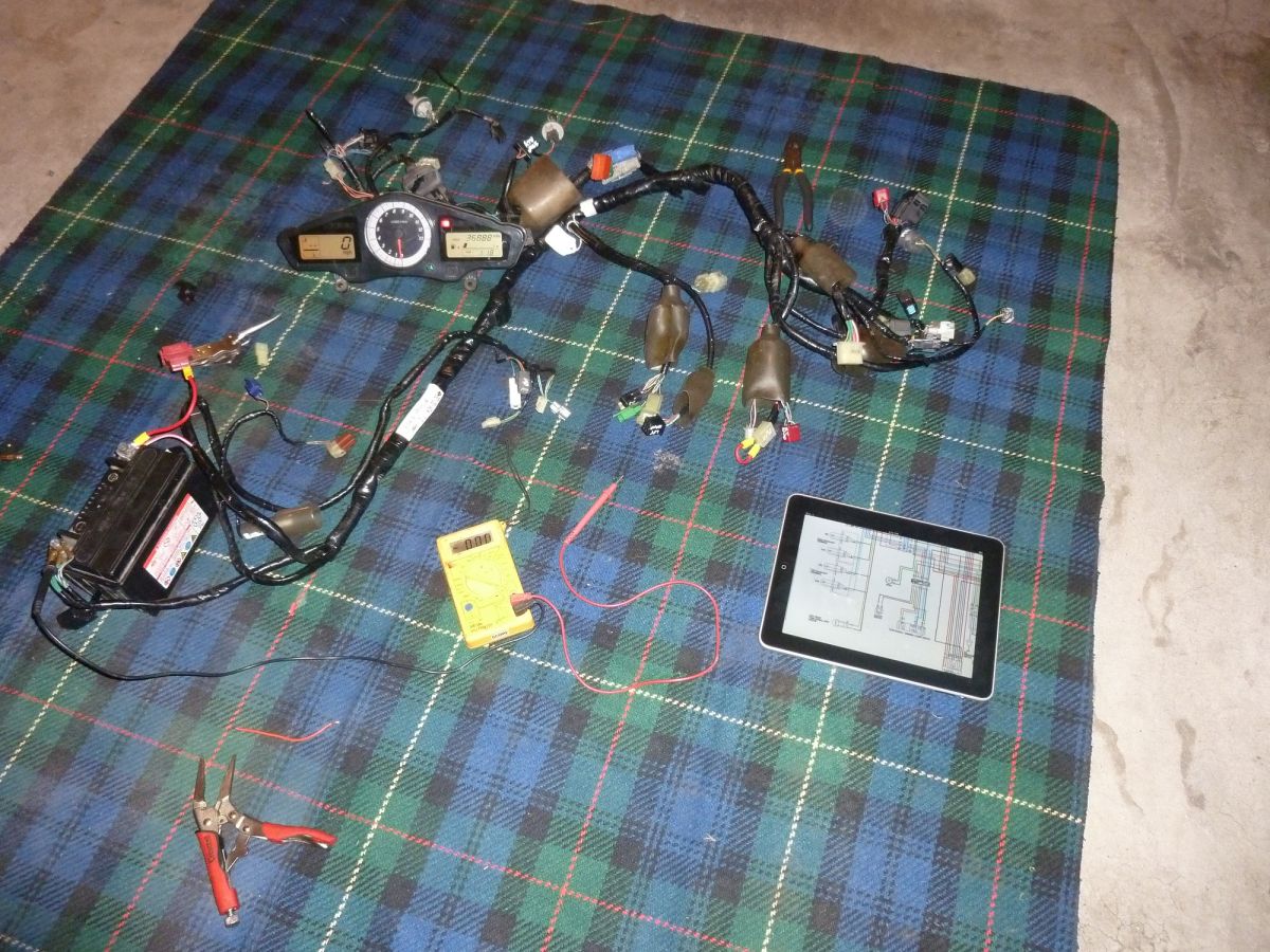
Basic wiring harness power test This is the initial test of the US wiring harness. Both the starter relay positive and Main Fuse B positive were wired to the battery along with the main ground wires. No fuses were used - NAUGHTY!
I have a USA model 2006 dashboard lying around, so first I checked the clock worked as soon as battery power was applied, and then I jumpered the ignition connector to emulate the key being in the ON position to confirm the dashboard powered up.
Before performing this test I had already re-wired the ignition switch to the Aussie 2002 specifications and bypassed the hazard relay. I could not test that yet though as I'd need to strip all the relays off my bike and I honestly couldn't be shagged tonight.
Note: iPads are very handy for looking at wiring diagrams!
-
And have you considered my suggestion of getting your hand on a RHS handlebar switch module?? Just to avoid cutting and splicing into the harness so much...
Nope! Using a US module would actually require more work as I'd need to buy the hazard relay for it ($50+) and both the turn signal diodes ($13 each) just to get the hazard function.
As it stands, my re-wiring job for the right-hand handlebar needed no splicing, just jumpering. The left-side handlebar is the only one that required a little tweaking to make the high-beam-flash work.
I'm quite enjoying the process anyway. :)
-
I just mentioned this because since I fixed this POS connector, all my surging issues have dissapeared... and it just so happens that lots of ground wires from lots of sensors involved in the FI system run through this POS connector... it may be worth trying before you become prematurely bald whilst attempting a complete wiring harness transplant...
Eh? The ground wires for nearly every sensor on the bike don't run through that block, they run through the block in the main harness, between the left-hand side of the engine and the frame. I'll take some pics if you like.
The block you're talking about is the sub harness ground block. Not saying it couldn't affect the ECU though - it's just not where the ECU and its sensors are grounded.
-
Well, the remaining wiring connectors are taken care of too!
Connecting US main harness front brake switch wires to Aussie 2002 handlebar wires
OK if pin location in connector block is the same. Black/Green wires from handlebar wires must connect to Brown/Black and Green/Yellow on main harness connector. Order not important.
Connecting US main harness engine stop switch wires to Aussie 2002 handlebar wires
OK if pin location in connector block is the same. Black must connect to black, and White/Black must connect to White/Black.
Connecting US main harness Starter switch wires to Aussie 2002 handlebar wires
OK if pin location in connector block is the same. Yellow/Red must connect to Yellow/red, Brown/Blue must connect to Brown/Blue, and Blue/White must connecto Blue/White.
Connecting US main harness hazard switch wires to Aussie 2002 bike without hazard lights
- On main harness, remove Black/Brown wire from hazard switch connector block
- On main harness, remove Red/Blue wire from two-pin connector block (Red/Blue and White/Red) near hazard block
- On main harness, join Black/Brown wire with Red/Blue wire.
Connecting US main harness clutch and horn switch wires to Aussie 2002 handlebar wiring
- On 2002 main wiring harness, cut left-hand handlebar two-pin connector from harness with 5cm of wire remaining.
- On main wiring harness, remove Green/White wire from left-side 9-pin handlebar connector block
- On main wiring harness, join Green/White wire to 2002 harness two-pin connector block Green/White wire
- On main wiring harness, remove Light Green wire from left-side 9-pin handlebar connector block
- On main wiring harness, join Light Green wire to 2002 harness two-pin connector block Light Green wire
Connecting US main harness turn signal wires to Aussie 2002 handlebar wiring
No change required; handled by turn signal relay and right-hand handlebar wiring.
Enabling high beam flash/pass switch to US main harness
- Purchase new single pin connector block
- Create new splice wire approx 20cm in length of 10 amp cable
- Wire one end of splice wire to female side of new connector block
- On main harness, splice other end of splice wire to Brown/Blue wire at white connector block
- On handlebar wiring, remove Brown/Blue wire from 9-pin connector block
- Connect the brown/blue wire from handlebar wiring to male side of new connector block
Connecting US main harness dimmer switch wires to Aussie 2002 handlebar wiring
No change required as long as pins on either side of connector block match up. Blue must connect to Blue, and Blue/White must connect to Blue/White.
- On main harness, remove Black/Brown wire from hazard switch connector block
-
Never mind what the GSXR uses for a plug gap!!
IF you test one of these COP's connected to the VFR, what does the spark look like??
Is it bright blue white with a vicious snap?
Hang on. What you're saying means that you know that over-charging the primary coil results in a higher voltage in the secondary winding. Which also means that we're assuming that over-charging the coil is cool.
Shouldn't we focus on confirming that's fine first, and then worry about the spark gap adjustment to compensate for the higher voltage?
-
Righto, I'm all over this like white on rice. I've designed wiring fixes for the turn signals and also the ignition switch. Next up is the Engine Stop, Starter and hazard switch block, which looks a tad harder.
Connecting US sub-harness Turn Signals to Aussie 2002 bike without hazard lights
- Make jumper wire from 10 amp wire, one end with spade connector, one end bare wire
- On sub-harness, connect jumper wire blade-end to Left-side hazard diode grey wire socket.
- On sub-harness, splice bare end of jumper wire to Grey/red wire at Turn Position Relay socket
- On sub-harness, jumper orange/white to Orange at Turn position relay socket
- On sub-harness, jumper Light Blue/White to Light Blue at Turn Position Relay socket
- On sub-harness, tape up all other hazard diode sockets and Turn Position relay socket for weatherproofing
Connecting US main harness to Aussie 2002 ignition switch
- On main harness, disconnect red/white wire from Ignition switch socket
- On main harness, splice red/white wire at ignition switch socket into Red/Black wire at ignition switch socket
- Make jumper wire from 10 amp wire, one end with spade connector, one end bare wire
-
 indeed.
Hang in there mate. You are blazing a trail; hopefully it leads somewhere you wanted to go.
It's OK. I sat down, had a couple of beers and planned my way forward. It goes like this:
- Make a list of the circuits with issues.
- Investigate each circuit's wiring requirements
- Draw up a plan to re-wire each circuit correctly
Whilst twiddling with the sub harness this evening, I attacked one of the circuits I know will have a problem - the indicators. I worked out how this circuit works exactly on my current harness, and so now I know how to wire this one up on the new harness.
- Make a list of the circuits with issues.
-
BTW did you do THIS yet?
No actually I haven't done that; never had any issues with the front end wiring so never bothered. That connector block BTW is much easier to get to on the 2006+ wiring harness as it's right by the blue and white connector blocks. So if I ever NEED to work on it in future it should be a tad easier.
-
Ruh-Roh! This is going downhill rapidly.
So, you yanks don't get high-beam flash/passing switches I see! Also your wiring harness seems to route the left-hand handlebar wiring completely differently to the Aussie bikes. Yay!
And I see your ignition switch has four wires but mine has three. Yay!
Gosh, the right-hand handlebar wiring is all completely different colours too. Ace!!!
OH. MY. GOD.
I've really dug myself a hole this time. Ohhh yeah. Get out the
folks coz this is going be a laugh-fest.
Installing 2006+ ECU and motor on 2002-2005 6th-gen
in Modifications
Posted
Thanks Bailey. You always come back with support and I really appreciate it. Truly.
I'll get there. I'm going to borrow my father's '97 VFR while I work on this so I can keep the bike in bits rather than reassembling it every night. The problem is evident even at idle so if I can trace and fix it there I think it will be licked. I need to have some patience and wait for my spares though - coils and fuel pump on their way. I'm very impatient, so having a spare bike to ride around on will help force me to back off a bit and do more thinking and less rushing.
Having my current probe which Seb shipped to me will also help. It means I will be able to run actual tests which can tell me whether a part is or is not failing, rather than take a guess and then doubt myself.
Ultimately I'm hoping this problem is not the new parts, but rather them showing the existing problem in a worse light. It certainly behaves just like it did, but worse.