

kaldek
-
Posts
1,317 -
Joined
-
Last visited
-
Days Won
11
Content Type
Forums
Profiles
Gallery
Blogs
Downloads
Events
Posts posted by kaldek
-
-
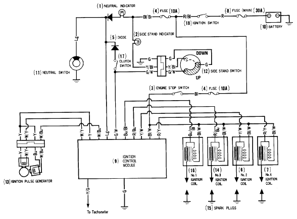
Lookee what I found - a 4th-gen ignition diagram.
So it's definitely TCI, as all the coils share the same 12 volt feed from the engine stop switch. Same wire colour as on the 6th-gen too - Black/White. This wire colour is used as the common 12 volt feed for anything which needs a 12 volt source all the time the ignition switch is on and the Engine Stop switch is on.

-
I actually didn't know the difference between CDI and TCI and had been viewing everything as TCI.
Checking into it though, since all the coils I've seen are 1.6 or 3.2 ohms I don't think they're CDI - those apparently have very low resistance (0.3 ohms or so). It's impossible to measure the resistance of the 6th-gen coils because they have the transistors inside the coil itself. I would guess that the 6th-gen is also TCI, as the coils are permanently fed 12 volts on one wire, have a dedicated ground wire and the third wire is the switch. This single wire should reasonably only be able to control a transistor that switched the 12 volt feed into the coil on (charge the coil), then off (collapse the field). So it's most likely TCI.
Another way of checking if a bike uses TCI or CDI is to look at the way the coils (2-wire coils anyway!) are powered. If they share a common +12 volt feed and have individual ground wires going back to the control box, then they're TCI. However if they share a common ground but have individual positive wires going to the control box, then they're CDI.
-
So, I wire it up like these then?
Yep that's the way it's done. It only ever works if one of the new coils is half the resistance/ohms of the oil dual coil pack. So even though some of your other bikes will be dual-coil they may not be 3.2 ohms.
If the original dual coil packs are much lower than 3.2 ohms, you will overcharge the new coils (too long a dwell time) and blow the coils/wear the plugs out fast, or undercharge the coils (too short a dwell time) and get poor spark. Unless your CDI has closed loop dwell control of course, in which case pretty much anything should work.
-
Located my F4i coils. Turns out I only have 3. DVM set to ohms, two of them slowly came up to 1.1/1.2ohms, the third spiked up to 1.4 then settled at 1.1ohms.
I'm going to think up a prize to offer to the first person to figure out how to make these work on a 4th gen...
That's easy - run them in series as wasted spark. It's already a dual-coil (rather than quad-coil) setup isn't it? If it's wasted spark 3.4 ohms each coil with dual coils you just wire two 1.6 ohm stick coils in series. (1 & 4 and 3 & 2).
-
Friend of mine has performed this procedure recently on his 2006-on VTEC...
Since then, it backfires and in fact, even though he manages to get all valves in synch, the values he gets are low (14 mm/hg) and they are usually around double that I think.
What could it be?
Are the two tubes that conect to a brown two-way connector on the RHS of the air-filter box to go in a certain order? What happens if you put them back on switched around?
He can't find anything out of place so we are wondering if the 2006-on models have anything different to keep in mind...
He's probably disconnected another vacuum hose accidentally, probably the fuel pressure regulator hose. It connects to the two right-hand side cylinders so he's probably tried to sync the bike to cylinder #4 when that was already out of whack. There's also the flapper valve vacuum hose on the front left cylinder, and if it's a US-model bike with the evap cannister it has an extra vacuum line again for ALL the cylinders which can also be accidentally disconnected.
-
Honestly, this argument has been done to death in various forms. People spinning their fans backwards because "it's better than the Honda design" went on, and on, and on.
So how about a link then? As I said in my OP, I've read plenty on the fan mod but have never seen a discussion on routing the hoses differently.
Sorry I meant the "spin your fan backwards" thread.
http://www.vfrdiscus...6th-generation/
http://www.vfrdiscus...e__hl__radiator
Basically lots of folks saying the stock design is flawed, yada yada. But, has anyone heard of a VFR overheating and warping the heads? I've been on the forum here for ten years and I don't recall a single one.
My opinion is that the stock design works best when the bike is stationary or moving slowly. If you flip the fan, it will work WORSE when the bike is stationary because it's pulling already-hot air from the engine rather than cooler air from the outside. Someone at Honda ran the numbers on this and they were obviously right, because no VFRs have yet overheated and blown head gaskets or warped heads. In this case, stock works.
As for the running the radiators in series, you may find that the pump hasn't got the balls to move the coolant around and may just cavitate, creating a lot of froth and not much movement of coolant.
-
I have no doubt that a parallel system is efficient when the bike is moving along with some airflow.
But moving in slow traffic with reduced air flow thru the radiators would seem that a series system would work better.
Honestly, this argument has been done to death in various forms. People spinning their fans backwards because "it's better than the Honda design" went on, and on, and on.
Have you seen the cooling fan on a CBR1000RR? It's about one-eighth the size of the radiator, in the upper right corner. That's it - and it works.
Our bikes have two radiators, and the fan is basically the same size as the entire left-side unit. It's fine, it works, and I've seen it keep my bike at 231F when the ambient air temperature was 116F! This was in traffic, too.
-
Can anyone advise if this model would need the rotor replaced as well as stator - obviously hope not as this would make job much easier. Also any idea of outer diameter for 2006 model - is it the 107mm or 115mm???
Rotors don't wear out, so no need to replace. Outer diameter of original 2002 model stator is 107mm. Outer diameter of upgraded stator is 115mm. I have one of each in my garage just lyin' around.
-
 1
1
-
-
Is there a difference between blocking off the PAIR valve & just disconnecting the PAIR wiring connection on the 6th Gen? or do you have to do both?
You cannot just disconnect the wires because the PAIR system is enabled by default when there is NO power applied. Only when power is applied does PAIR shut off (it closes a valve). PAIR is always active except when the engine goes into closed loop mode (i.e. the O2 sensors trim the fuel), which is not very often.
Sticking a marble in the hose that comes from the airbox and goes to the PAIR valve solenoid will do the same thing as the PAIR block off plates. You need to raise the idle speed as well, and potentially adjust the fast idle wax unit as this controls cold engine idle speed. Both are affected when PAIR gets blocked off.
-
Yeah same procedure for all HISS bikes.
-
You are the Guru my friend.
So does it still run rich on cold start?
Yeah, but testing continues. I'm waiting on the diagnostic tool from HealTech so I can see what the ECU thinks is going on. I'm also going to do valve clearance checks and some other mechanical checks to make sure the problem is not being caused by some form of issue affecting engine vacuum.
-
If you lose all the keys to an Australian or European bike, you are faced with an expensive prospect to get the bike running again, as the ECU is coded to transponders in the keys (via H.I.S.S). It is possible these days to have your old ECU reprogrammed via some folks on eBay, but what if you find an American ECU somewhere much cheaper?
Unfortunately Honda expected that nefarious folks might try this when stealing motorcycles, so they modified the wiring harness. American ECUs won't work on European or Aussie wiring harnesses - or will they?
I mapped all the pins on both my Aussie wiring harness and American wiring harness that I happen to have lying around. It turns out that the only difference between the two harnesses is that American systems use two power feeds into the ECU rather than one. Both feeds are the black/white wire, which is the +12V signal from the engine stop relay. Anyone familiar with the 6th-gen wiring will know this is the circuit used to power pretty much the entire FI system (PAIR solenoid, EVAP solenoid, airbox flapper solenoid, injectors, coils, fuel pump relay).
So in order to get your USA ECU to work on a Euro bike, you need to remove a pin and wire from somewhere else on your ECU connector plug, and move it to the pin where the additional power feed is needed. This pin is on the grey connector, pin #16. Once you have inserted your relocated pin into this hole it will clip into place, and you can then splice the wire into the black/white wire from the engine stop relay. The wire you relocate can be any of the following pins from the grey connector, as they are not used on the USA model ECU:
- Pin #1 - Blue wire
- Pin #12 - White/Red wire
- Pin #14 - Pink Wire
- Pin #32 - Orange/Blue wire
Note that this process is specific to 2006 and newer models. Older units may "just work" or may also require relocation of a pin.
WARNING: You cannot put an ECU from a 2002-2005 bike on a 2006+ model bike without also replacing the wiring harness, as the ECU hardware and connectors are totally different.
- Pin #1 - Blue wire
-
I lost almost all pressure in the rear brake pedal and front brake lever... (track day)... due to high temps and thus expansion of rubber lines..
Wow that must be one tight track!
-
"Yes, I opened Pandora's box when I started twiddling... "
True, but think of how much you (and we) have learned.
Thanks for sharing.

Thanks mate, I really do appreciate comments like that!!

-
Forgive my ignorance but what is the benefit of the US vs. Aussie/Euro version? Normally you hear how they "tame" the US version for one reason or another. I'll probably never have to deal with this but just knowing the difference has my curiosity piqued.
Good question! I bought the USA ECU (and wiring harness) as a cheap method of replacing my 2002 model ECU, because US bikes do not have HISS and therefore you don't need matching coded keys. What I wanted was to upgrade to the 2006 ECU over the 2002 unit, because of the benefits of the newer ECU hardware (better throttle response).
After putting that ECU in, I had other issues still related to my 2002 motor which meant that in the end I bought an Aussie 2006 donor bike for parts and used the wiring harness and ECU from that bike. That bike brought its own problems - rich running - and I wanted to go back to testing the USA ECU I bought initially.
Yes, I opened Pandora's box when I started twiddling. I just can't leave it alone!
-
Well folks, I finally worked out how to get a USA model ECU working on a Euro/Aussie 6th-gen VFR. Took me a while though as I had to map all the pins on each ECU until I found the culprit, but it's actually a very simple difference. Note that the following is only guaranteed on a 2006+ model bike.
- The USA ECU has two power inputs into it. They are both the Black/White wire 12 volt input from the engine stop relay, and one goes to the black connector while the other goes to the grey connector.
- The Aussie/Euro ECU only has one power input. It is also the Black/white wire but only goes to the black connector.
In order to easily drop in a USA model ECU into a Euro Aussie bike, you will need to add a pin and wire to pin #16 on the grey connector, and then splice that wire into the black/white wire feed from the black connector. Once this is done, the bike will fire right up.
Now, there's a small "gotcha" here. And that is the fact that you need to find a connector pin from somewhere! Unless you happen to have a bunch of wiring harnesses lying around (*cough* Kaldek *cough*), your only option will be to remove one of the pins used for the HISS circuit and move that pin and wire across to pin #16 on the white connector. I haven't traced exactly which ones of these is the best source, but once I do I will add that to this post, along with some pics. :-)
If you plan on only making this a temporary modification, I would put a switch on the spliced wire feed into Pin #16 so you can safely cut that circuit before you connect an Aussie/Euro ECU back into the wiring harness. If you don't do this, I guess there is a chance that you could create an internal short circuit inside the ECU (which would be bad).
- The USA ECU has two power inputs into it. They are both the Black/White wire 12 volt input from the engine stop relay, and one goes to the black connector while the other goes to the grey connector.
-
I would say this job is only cheap if you just focus on the front master cylinder and the five pistons (three right, two left) it activates. There are kits available for this job which are very cheap ($119 AUD), and consist of a long banjo bolt for the front master cylinder and two hoses - one to each caliper.
Essentially that would take care of the majority of braking problems right there.
-
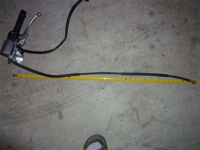
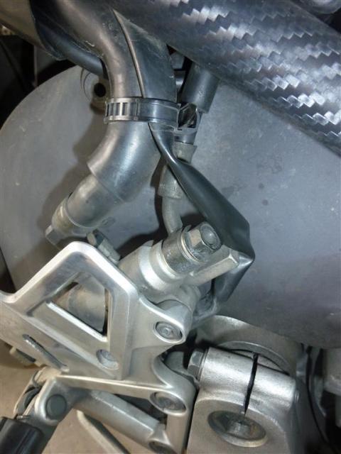
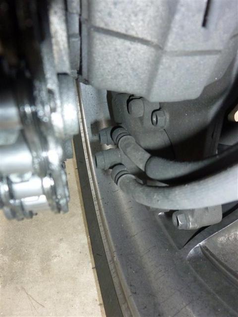
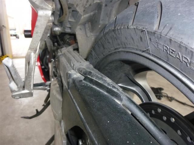
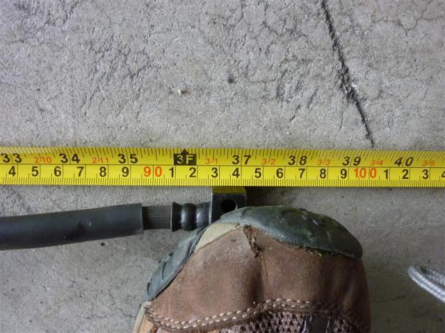
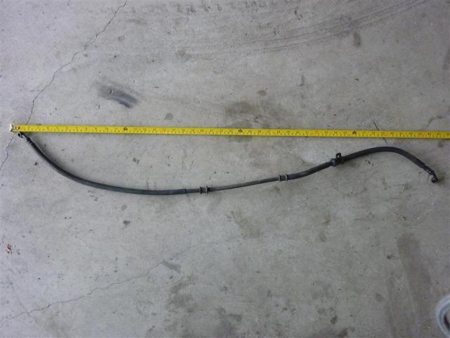
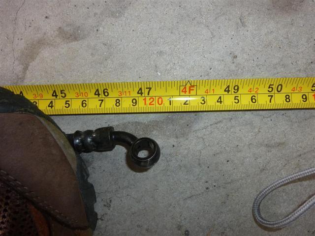
The pic with your foot, is that the line pulled taught(straight)? Or is the line slack in that pic as well?
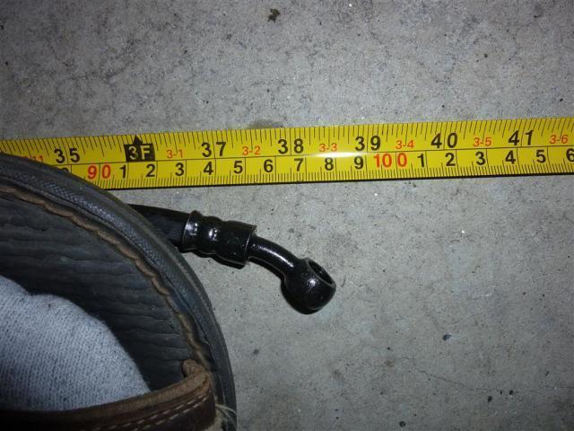
No, each pic that I zoomed into I pulled the hose straight.
-
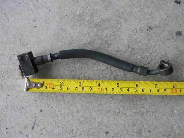
Clutch line.


-
Clutch?
LOL, OK OK I'll go do that!
-
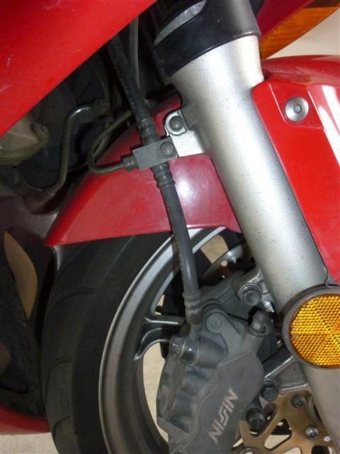
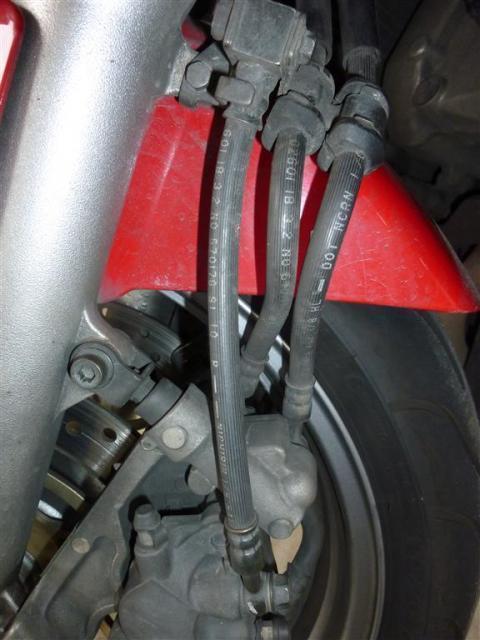
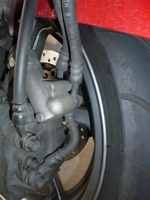
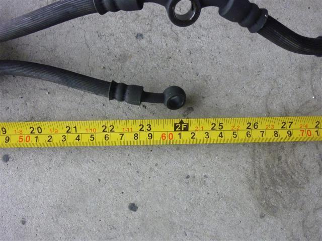
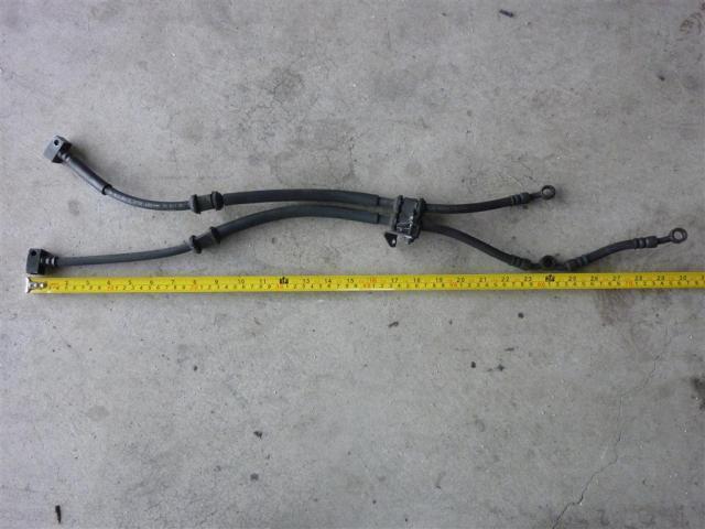
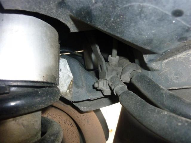
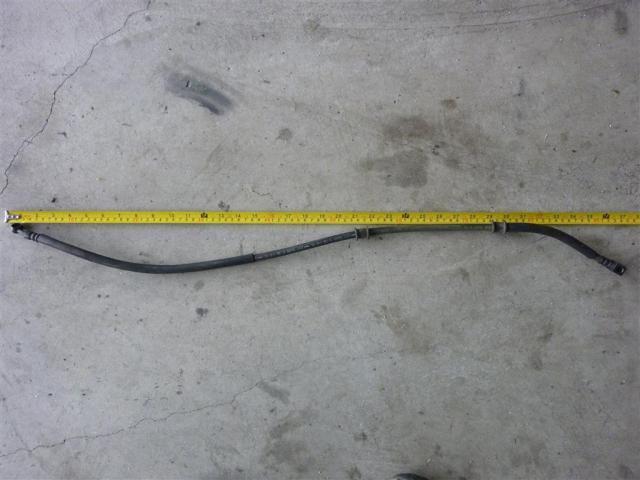
For anyone wanting to replace their 6th-gen hoses with braided lines, here are some pictures of all the hoses and their lengths. Note that if you wish to replace the CBS hoses you will need to interface your new hoses with the blocks which interface with the rigid hoses that connect from the front to the rear of the bike.
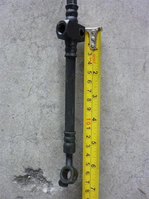
Right Front Caliper Hoses (Warning - needs T-piece and extra hose for right-to-left crossover at least 10 inches long OR needs two hoses from master cylinder to right and left calipers)


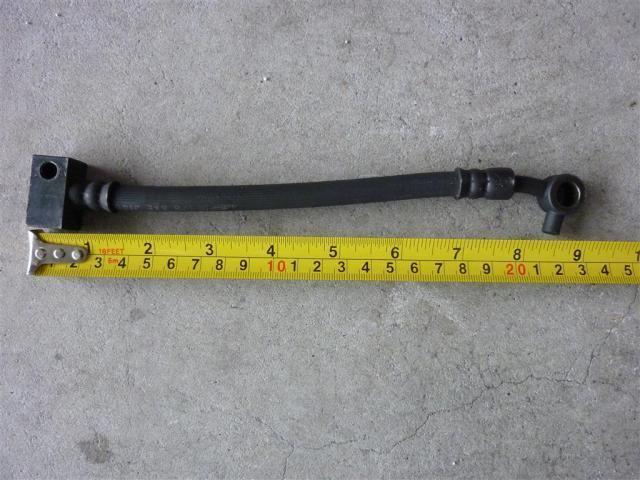
Left Front non-CBS (main) hose


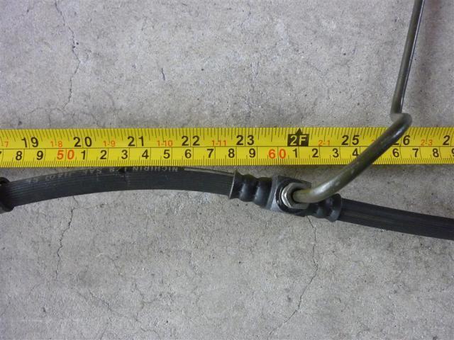
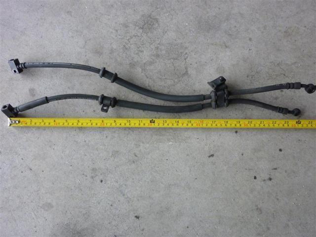
Left front CBS hoses (connects to rigid hoses) WARNING - SPECIFIC TO 2006 AND NEWER BIKES ONLY. 2002-2005 HOSES SLIGHTLY DIFFERENT LENGTHS.


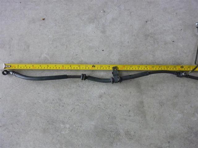
Rear pedal hose


Rear caliper hoses


-
1
-
-
cheers kaldek, payment and address sent though.
Not a prob I'll get those sent out tomorrow.
-
hi kaldek, just ordered 2 blank keys, can i purchase 2 transponders off of you mate ?
Sure mate - yours for $8 shipped (they cost me $3.80 each so that'll cover them and postage). I'll PM you so you can give me your address and you can Paypal me the buckeroos.
-
Just curious why you didn't get them cut locally?
Timing. Ordering pre-cut keys was one less step needed to get the job done, otherwise it would have been waiting for postage and then having to go see a key cutter. I only trust locksmiths and there aren't any nearby, so it would have eaten up a lot of my time to get it done.

5th gen "coil on plug" setup.
in Modifications
Posted
Well it tells you that the bike is most likely TCI and that by merely looking at your wiring diagram you can confirm it. That means that the use of four Coil-On-Plug items of the same resistance as the existing coils will work fine, and a coil of any resistance should work fine if the EFI uses closed loop dwell control (which we haven't confirmed).