


kaldek
-
Posts
1,317 -
Joined
-
Last visited
-
Days Won
12
Content Type
Forums
Profiles
Gallery
Blogs
Downloads
Events
Posts posted by kaldek
-
-
17 minutes ago, Grum said:
Hi Kal.
Welcome back after such a long hiatus. Your knowledge of all things VFR is highly respected.
Best Regards.

Cheers mate. Been a long time indeed. I shamefully don't ride much at all anymore as I work from home since 2015 and I've also stupidly gotten back into cars as well.
-
Hi! Bit of a lurker these days but had myself a 2002 model that I put 200,000km on and burned up a stator or two.
The stator colour is not indicative of it being burned out. Due to the oil levels in the crankcase, half of the stator is permanently cooled by the oil and the other half is not. Ergo it gets a burned appearance to it. It's likely that's where the failures occur due to the higher heat but it doesn't immediately mean anything.
The stator fails in basically one of three ways:
- Short to frame
- Short between phases
- Short within a phase
The way that the stator works with regards to the above is that there are 18 separate poles which make up the three phases (6 for each phase). Each pole has heaps of insulated wire wrapped tightly around the frame of the stator in a coil. This wire is thin copper wire with integrated insulation, similar to speaker coil wire. The wire needs to be a tightly wound coil with no shorts in it in order for the magnetic fields to work. Around the outside of the wire is an epoxy paint coating to protect the coils of wire. This epoxy coating is what is becoming discoloured.
Anyway the shielding around the coils of wire can break down. This either shorts the coil to itself, to the frame of the stator (and therefore the frame of the bike) or between coils. Either way, what happens is that the stator can no longer generate enough energy.
The regulator/rectifier is sent three separate alternating current feeds from the Stator. It takes each one and rectifies them to DC using a bunch of diodes, and afterwards regulates the voltage down to 14.4 volts or so (P.S. it's the regulation from high DC voltages down to 14 volts that heats up the regulator and causes it to burn out).
If one of the phases is producing a low voltage, the total final output of the R/R into the bike's charging system drops. You can have a weak phase (short within a coil to itself) where the voltage is reduced or perhaps an entire phase going dead.
None of this discusses failure of the R/R itself, and there is plenty of material (some it mine from pre-2011) here on the forum about different models of regulator/rectifiers can be installed to manage this problem and reduce or remove the risk of R/R failure.-
 2
2
-
 1
1
-
Come on son, it's sad to see my old bike still not running!
(Slinks back into the corner)
-
Sooo, me being a long forgotten but still lurking member can chip in.
I bough a 2002 model brand new off the showroom floor in March 2002 the day after I was legally allowed to ride large capacity bikes. Put 128,000km on the original motor with no mechanical issues other than needing to replace the Cam chain tensioners (three times), the stator (twice), and the clutch disks (once).
After that I tried to be a smartypants and get it tuned, yada yada. Ended up dropping in a 2006 motor and American ECU, plus Motad headers. It never really ran right after all that and I by this time I had 185,000km on it. Got bored and bought a BMW K1300R. I've had that bike for 3 yrs now and 40,000km. It's fast but boring compared to the VFR. I miss it.
On a side note, my original 2002 motor and the 2006 frame is still getting around on this forum being ridden by MVinOz as a track bike.
-
This has been discussed a lot over the years.
OEM sprocket and aftermarket sprocket, some move and some don't. I think I even asked the same question here once back in 2005 or so. It's not a problem. however I got paranoid and made up a small spacer out of an old coke can to keep it secured.
-
You need one of those IR camera guns. Look for the hot spot because that's where your current draw is. Whatever that problem is, 0.45 amps of draw is gonna be warm.
-
This is why I bought a K1300R. Still has pannier option, and can mount a topbox (with parts from SW-Motech).
-
I've had Shorai LFX batteries in my bikes since 2011. Absolutely no problems, ever. Well over 100,000km of riding. My current bike - the K1300R - starts like a champ even if I leave it for weeks.
My poor brother in law has had a bunch of start failures on his ZX12R. Failed stator, failed regulator, failed starter motor. He has a Shorai LFX which has worn the brunt of these problems by getting drained flat a few times and heavily drained by the starter motor when that began to fail. The battery keeps on ticking though.
In particular, when the charging system totally craps out, the bike runs longer on the Shorai than on lead acid. This is due to way Lithium batteries hold voltage for longer. Sure, they eventually drop off a cliff but lead acid tends to drop from 12 volts down to under 9 volts long before the rated capacity is used up. And at that point your fuel pump and coils stop working.
-
That's right, I did purchase the HealTech unit, which I then sold to Auspanol if I recall. It collects very little raw data because very little data is available. There are only about 30 error codes and none of those are intelligent ones like "O2 sensor rich" or anything useful.
They are notoriously hard bikes to diagnose for EFI issues, unless you happen to be a master auto diagnostics technician with a kick-ass oscilloscope.
Honestly I can't wait for the day the USA forces OBD2 standards on motorbike manufacturers. OBD2 was brought in in 1996 in the USA, but if you have a European or Japanese market version of the same car sold in USA from that era, it still won't have OBD2! The manufacturers *really* didn't want to have to put the smarts into their ECU as it created a whole lot more coding work for them.
-
I've just had a quick read at the first page of this.
What octane rated fuel are you guys using? On the first page, 91 octane is mentioned and thats premium?
Here in the UK, 95 is normal, 97 is premium and 99 is available in some places.
USA uses different rating system - RON+MON/2. It's called AKI or the Anti-Knock index.
Ergo, 87 US Octane is roughly 91 RON. So 91 US Octane is roughly 95 RON.
-
Did another Partzilla order, should have all the bits to secure the rear subframe in a few days, then I can take it for a test ride :)
I hope all the stuff you had to buy hasn't made it an expensive bike. I have a habit of buying projects that end up costing me money.
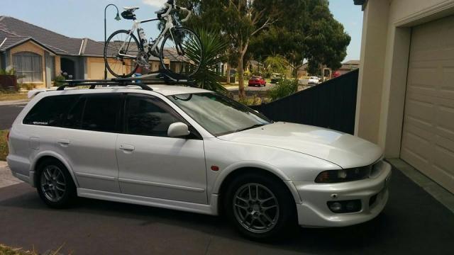
Like this year, for example. I bought this (without the bike - that's a recent pic from last week):

It's a twin turbo AWD V6 wagon imported from Japan - a Mitsubishi Legnum VR4 to be exact. Sorta like a DSM 3000GT VR4 mechanically. You yanks will tell me it's a Galant wagon, which is true. It is in fact a Galant, just a fast one that they only ever sold in Japan.
It was cheap - only $6,000!
Then I discovered the clutch was shagged. $700 in parts
Then I discovered it needed the 60,000 mile service. $700 in parts.
Then I had it custom tuned, but it turned out the last owner stuffed the fuel pump. Tune took more dyno time, needed new fuel pump. $1,000 all up.
Then the freaking timing belt tensioner bolt snapped. Amazingly, didn't skip teeth but it still took 9 hours of my mechanic's labour and new parts. $1,200.
Yeah. It's been a fun year. Still, the car is a whole bunch of fun to drive: 0-60mph in about 5 seconds, plus it's a wagon and I can put stuff in it!
-
Geezus, you turn you back for a moment and THIS happens!
Seriously mate, I'm super proud and I'm also sorry for any hassles you had with the parts. That rear axle looked super frozen; you can see why I had to cut the swingarm pivot to get it off!
-
OK guys we need a little sanity here. I've pulled this model bike apart too many times to count and done a lot of diagnosis. Here's what I can tell you FOR CERTAIN:
- The VFR ECU has no "long term fuel trim". The O2 sensors ONLY kick in when the bike is cruising.
- Fitting O2 eliminators will completely STOP closed loop mode. This means that the ECU will not "adjust" fuel. Ever.
- Any bike running with O2 eliminators will stay in Open Loop mode permanently
- The PAIR valves are open by default and ONLY close in circumstances where the O2 sensors would normally kick in
So, what does all this mean? It means if you fit O2 eliminators, your fuelling issues have ZERO to do with the O2 sensors.
Now, about the TPS sensor being faulty. I cannot speak with certainty on this topic, but the VFR ECU is a mix of Speed-Density and Alpha-N fuelling. What this means is that at low-mid throttle positions, the ECU uses the Manifold Absolute Pressure (MAP) sensor to control the fuel mixture. At larger throttle openings, the ECU switches to "Alpha-N" which means the fuelling is based on only the Throttle Position (alpha) and the engine rpm (N).
What kind of things can go wrong here?
- Air leaks in the MAP hoses would probably make the bike run lean, not rich
- The TPS *could* be out of alignment. This could be checked by looking at the TPS screws to see if they have been disturbed, because they are glued and set in place once adjusted at the factory.
The reason the "TPS fix" is so expensive is that Honda won't sell you a TPS, you have to buy the whole throttle body assembly. I had a zillion spare parts for this bike, including an entire assembly. I sold it all to member MVinOZ so if you want to contact him to see if he has a throttle body handy, you could pick one up for very little.
-
Take a look here: www.bmwmoa.org/forum/showthread.php?30909-BMW-Final-Drive-Failure-For It's long, ugly and mostly K bikes, it seems.
Can't see anything in here, and the website it links to doesn't have any relevant info on it anymore (lots of 404 errors on that website).
BMWs are a bit off topic though so I'll stop there!
-
Hmmm. This is the fourth one of these I've heard of. This is starting to sound like the BMW forum. Maybe a little chain lube and adjustment now and then isn't such a hassle after all.

I don't hear much about the newer K1200/K1300 bikes having final drive issues. Seems to be mainly the R1200 series bikes.
-
BTW, I test rode an '07 K1200RS, which is the half-fairing cousin to the R. Very nice package, and felt lighter at parking lot speed, probably due to the higher and wider bars. VFR1200 feels like a proper sporbike in comparison - tighter, better feedback, and more engaging. I think you'll like it.
Uh, no it 'aint. K1200RS is based on the older K motor which was a flat four that was longitudinally mounted. Very, very different bike to the K1200R which has the hossack front end.
hey gang...made the deal yesterday...she will be delivered monday...
Ended up getting the bike for 7800!!!
Good price. Personally, I bought a K1300R over the VFR1200. In my opinion, it's a better bike. More power, better fuel economy, bigger tank (20.5 litres with the well-known 5 minute modification), and handles just as good.
A few magazines reviewed the K1300S and compared them to the VFR1200, and said they couldn't really split them if you're into sports tourers. Other magazines have then gone on to say that the K1300R is a more engaging bike than the K1300S. Which I suppose is why I bought my K1300R.
The VFR will probably feel like a step up from the older model K1200R though, so enjoy!
-
This supposedly is the new motor.

That's the 2002-2010 motor for sure. Looking at the throttle bodies, I'd be expecting that Honda would finally update to a returnless fuel rail with no fuel pressure regulator on the rail, so this also tells me this is the older motor.
-
Can anyone confirm Honda has ditched the side-mounted radiators? They just do not work in summer temperatures.
Yes they have been ditched. However, I owned my 2002 for ten years and I live in Australia where it gets up to 45 degrees C (113F). Never overheated once.
-
And this is why I use Dynabeads. I just drop 3 ounces into each tire and I'm done. Smooth as silk!
FYI I have tire pressure sensors in my wheels, hence the need for 3 ounces.
-
One of those psuedo science catalyst things?
This. It's a Fitch Fuel Catalyst.

Otherwise known as "1 kilogram of pure bullshit".
-
Shift Assist...........? Anyone care to elaborate on the details. Is that a stomp the lever with the throttle open affair?
Yeah it's basically a quick shifter. Works on upshifts only, cuts the fuelling just as you put pressure on the lever so that the bike shifts up into the next gear. I've got one on my K1300R and they're pretty cool, but they don't work unless you are on the throttle some. The hardest thing to do is get used to not feathering the clutch as you shift, otherwise it turns into an ugly clunky shift - worse than not having a quick shifter at all.
-
Looking good!
The LED lights consume a lot less energy than the previous halogen bulbs. Lower amperage => less heat (stator) & less thermal stress on the RR.Good point could be but why 420W stator ?
TECHNICALLY, not consuming the output of the stator is what causes heat. Probably explains why they will likely drop the stator output.
-
If you think that's good you should ride a K1300.
-
This is by my local state safety body, and it's probably the first campaign they've had that I have no problem with.
2002 Stator vs 2003-2009 Stator
in Electrical
Posted
Is that my post? I reckon I said something very similar back in the day.
I think even still have the flywheel removal bolt/tool in my toolbox.