


KanadianKen
-
Posts
1,159 -
Joined
-
Last visited
-
Days Won
12
Content Type
Forums
Profiles
Gallery
Blogs
Downloads
Events
Posts posted by KanadianKen
-
-
Good time to get Radars sliders - for us Northerners anyway.....
Just a bump for Radar - his product is excellent!!!!
-
nicely done. I'd love to see the light pattern they throw forward - say against a wall. I miss the HID's I had in my Maxima, they were the best lights I've ever driven with. :thumbsup:
As soon as it stops raining I will get the bike out and shine the lights against the garage door and post some pics. . :thumbsup:
well its snowing here like crazy, enjoy the rain!!!
-
nicely done. I'd love to see the light pattern they throw forward - say against a wall. I miss the HID's I had in my Maxima, they were the best lights I've ever driven with. :thumbsup:
-
Awhile back I had 6 wheel chocks for sale that were custom made as well.
Just out of curiosity what were you charging, I put a pencil to materials and my time to build a slight variation of this one. There is over $75 in materials and supplies involved in this monster. Plus to build this one I have about 20 hours in it, but figure that I could probably finish one every 6 hours or so (welding, cleaning and paint). So for me to sell these, I'd have to charge minimum of $150, and at that price, you can buy the harbor freight one that I listed above for $90, or stroll over to new enough and pick up the power stand for $120.
I think they were $125 - which was basically my cost.
-
Good Stuff Chris.
Awhile back I had 6 wheel chocks for sale that were custom made as well. (Same outfit that bends and cuts my brackets and fender eliminators).
THe materials aren't cheap, and the welding and bending is the critical part - as well as having a movable pivot to fit different tire sizes.
-
Thank you, Thank you, Thank you.
This article saved me hundreds of dollars of diagnostics at the shop.
I had no lights, blickers were affecting the fuel pump, etc....
MB
Cool - I guess its running better now?
 :thumbsup:
 -
8 spoker weighs 13.2 lbs. I weighed mine a couple weeks ago. Whats a 5 spoke rim weigh?
-
talus' volts are in Canadian, it translates up to about 14.3 - 14.5 American Volts................
Excellent job on the How to - you are hired!!!!! :thumbsup: :thumbsup:
-
thats a cool install. I liked Chris#### method but didn't want to plug off the center stem - plan to use that for a power outlet. :thumbsup:
-
Jeremy explained it to me best, so I will try to share the reasoning as best I can...
THe black wire coming out of the RR, connects with a white wire with a black strip. that wire is about 12 inches long, and connects with an uninsulated connection with a red power wire. That red wire continues on through the wiring harness, passes through another uninsulated crimp connection, a fuse, and then back onto the positive terminal of the battery.
WHat the wire (or set of connections) does is measure the voltage coming out of the battery so as to "tell" the RR how much juice to flow back into the battery, from the RR.
HEres the "WHY". With all those connections, and lengths of wire - often times there is a severe drop in voltage being read at the battery - versus what is really there. THe RR then doesn't send th eappropriate amount of juice back to the battery.
By doing this simple modification, you are simply making a very direct route to the battery - from the black wire of the RR.
If there are others with a better technical reason to do the mod - please feel free to add. thanks.
-
Some of the guys in other threads were using a 10A fuse on this wire.
I installed with a fuse on mine, but I think I may remove it to ensure it always reads accurately and terminal corrosion is not a concern.
What should I do?
Is it necessary for the fuse?
SOrry - I did install an inline fuse as well, with a 5 amp fuse. THe inline fuse I used was with 10 gauge wire - I hoped that any voltage drop caused by the extra connection, might be "saved" using heavy wire.
-
This is a step by step method to do the monitor wire fix. It guarantees a solid and direct connection to the positive battery post from the black wire coming off the RR.
Step 1:
Get your tool kit out. Spread a hotel towel down – so you don’t lose tools. Spread another down, to receive the bolts you will be removing. Sounds gay – but it’ll help long-term.
You need to get the fairing off: Here are the bolts and fasteners you need to remove. Any fasteners or bolts shown in the picture HAVE to come out. At the end – I took a picture of ALL the fasteners I removed. Make sure you got them all covered.
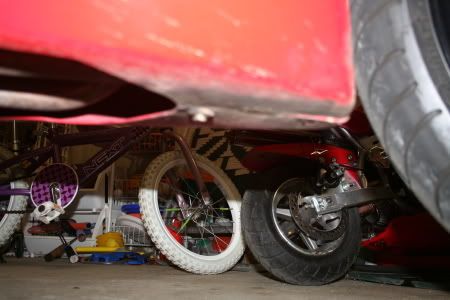
Under the bike – two fasteners. If they are round and have a “button” in the centre – push the button, then pull the outside part of the fastener out. I only have one on my bike- it’s a pain to remove as often as my fairings are off.
Three bolts you see here. Remember where each bolt came from – the bolts you will be removing are of different sizes.
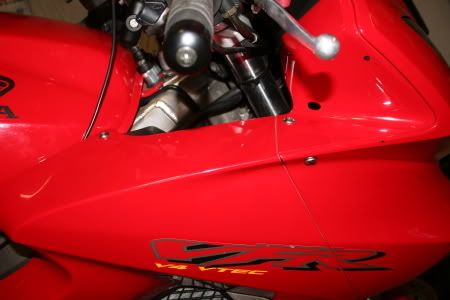
The bolt on the side comes out as well.
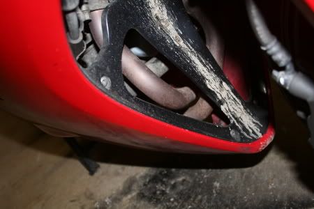
The two bolts on the black plastic centre fairing – the one on the top left, and the one about 7 inches down from that. Next to the mud stain on this picture.
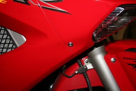
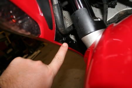
Looking to the inside of the right fairing, at the tip of my finger. Another of the mushroom type fasteners – press the centre, then remove the whole fastener.
The two bolts at 10 o’clock, and 6 o’clock.
Now the fairing isn’t attached. The best way to get it off is to be careful and pull the fairing out – away from the bike from the back part – the part furthest backwards from the handlebars. Then – take the fairing somewhere that you won’t step on it.
Step 2:
Locate the Regulator/Rectifier. Here’s what it looks like OFF the bike:
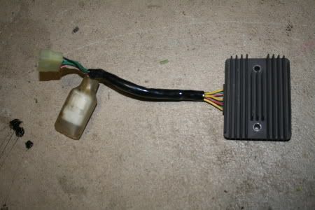
The part you are interested in is the connector that has the Green red and Black wires. The BLACK wire is the one you will be messing with.
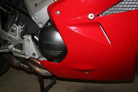
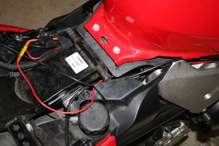
The RR is located here – on the right side of the bike. Carefully follow the wires coming out of the RR. Follow the wires to the connector.
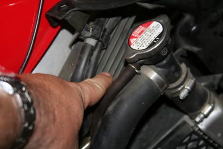
Here it is. There is a plastic rubber shield – just move it up and away from you – it’ll reveal the connector that you need to simply separate.
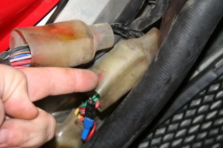
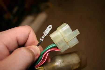
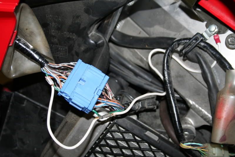
Here is the connector in one piece:
In the picture above, you will see green wires, red wires, and a white wire (actually a white/black wire.) That is NOT the half of the connector that you want to mess with. The side you need to manipulate is under my finger in the above picture.
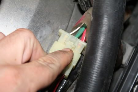
Push the tab in, and separate the connector.
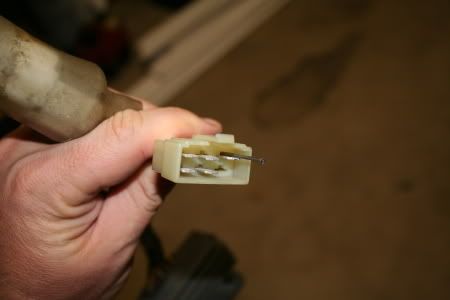
You should then see this:
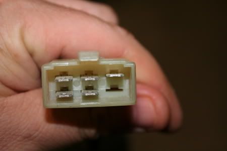
The wire connection you want to look at in the above picture is the top right connection. Notice the rectangular open space on top of each connector? This is where you insert a paperclip, a very small screwdriver, etc…. and press in with the tool of your choice. At the same time – pull the black wire out the other end. Here’s a couple more pics. I used a nail to push the tab in:
Ok – the hard part is over. Now reconnect the plastic connectors, leaving this black wire out and on its own.
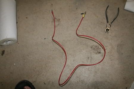
Now here is the what you need to create to complete the fix:
Get yourself about 3 feet of 12 or 14 gauge wire and strip off a bit of cover from each end: the following 3 pics illustrate: You will also need a RING terminal that is destined for the POSITIVE side of the Battery, and a female spade connector that connects to the Black male connector you just removed from the plastic connector.
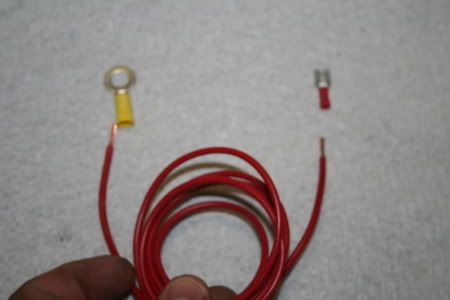
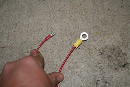
In my pic above – my index finger is on the wire with the female connector, and my thumb is on the ring terminal. Make sure you look at the size of the bolt on your battery (positive terminal) to make sure you get a ring terminal large enough to attach it.
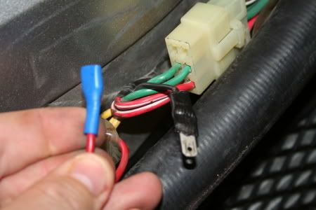
I attached the female connector to the black wire first, then routed the other end back toward the battery. Something like this:
And here’s what it looks like at the connection to the black wire: I used an insulated female connector – that is a good choice if you can find them.
Next – remove the battery cover, and remove the positive battery connection – and slip the ring terminal onto the bolt. Reattach to the battery.
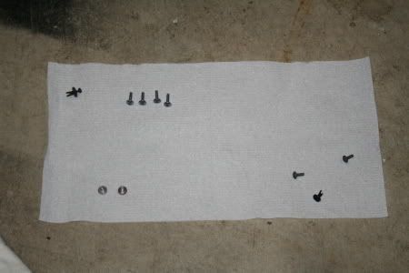
Next – button everything back up…… here’s the bolts and fasteners you removed:
-
 1
1
-
-
THis is a step by step method to do the monitor wire fix. It guarantees a solid and direct connection to the positive battery post from the black wire coming off the RR.
Step 1:
Get your tool kit out. Spread a hotel towel down – so you don’t lose tools. Spread another down, to receive the bolts you will be removing. Sounds gay – but it’ll help long-term.
You need to get the fairing off: Here are the bolts and fasteners you need to remove. Any fasteners or bolts shown in the picture HAVE to come out. At the end – I took a picture of ALL the fasteners I removed. Make sure you got them all covered.
Under the bike – two fasteners. If they are round and have a “button” in the centre – push the button, then pull the outside part of the fastener out. I only have one on my bike- it’s a pain to remove as often as my fairings are off.
Three bolts you see here. Remember where each bolt came from – the bolts you will be removing are of different sizes.
The bolt on the side comes out as well.
The two bolts on the black plastic centre fairing – the one on the top left, and the one about 7 inches down from that. Next to the mud stain on this picture.
Looking to the inside of the right fairing, at the tip of my finger. Another of the mushroom type fasteners – press the centre, then remove the whole fastener.
The two bolts at 10 o’clock, and 6 o’clock.
Now the fairing isn’t attached. The best way to get it off is to be careful and pull the fairing out – away from the bike from the back part – the part furthest backwards from the handlebars. Then – take the fairing somewhere that you won’t step on it.
Step 2:
Locate the Regulator/Rectifier. Here’s what it looks like OFF the bike:
The part you are interested in is the connector that has the Green red and Black wires. The BLACK wire is the one you will be messing with.
The RR is located here – on the right side of the bike. Carefully follow the wires coming out of the RR. Follow the wires to the connector.
Here it is. There is a plastic rubber shield – just move it up and away from you – it’ll reveal the connector that you need to simply separate.
Here is the connector in one piece:
In the picture above, you will see green wires, red wires, and a white wire (actually a white/black wire.) That is NOT the half of the connector that you want to mess with. The side you need to manipulate is under my finger in the above picture.
Push the tab in, and separate the connector.
You should then see this:
The wire connection you want to look at in the above picture is the top right connection. Notice the rectangular open space on top of each connector? This is where you insert a paperclip, a very small screwdriver, etc…. and press in with the tool of your choice. At the same time – pull the black wire out the other end. Here’s a couple more pics. I used a nail to push the tab in:
Ok – the hard part is over. Now reconnect the plastic connectors, leaving this black wire out and on its own.
Now here is the what you need to create to complete the fix:
Get yourself about 3 feet of 12 or 14 gauge wire and strip off a bit of cover from each end: the following 3 pics illustrate: You will also need a RING terminal that is destined for the POSITIVE side of the Battery, and a female spade connector that connects to the Black male connector you just removed from the plastic connector.
In my pic above – my index finger is on the wire with the female connector, and my thumb is on the ring terminal. Make sure you look at the size of the bolt on your battery (positive terminal) to make sure you get a ring terminal large enough to attach it.
I attached the female connector to the black wire first, then routed the other end back toward the battery. Something like this:
And here’s what it looks like at the connection to the black wire: I used an insulated female connector – that is a good choice if you can find them.
Next – remove the battery cover, and remove the positive battery connection – and slip the ring terminal onto the bolt. Reattach to the battery.
Next – button everything back up…… here’s the bolts and fasteners you removed:
-
i have the 1092 69/170 spring. sorry.
-
I figure since I can't use the new Ohlins Spring I got from that Ebay deal, I'll put it to good use anyways.
ITs summertime, its hot, and beer needs to be cool. Real cool.
I will place the Ohlins spring in the freezer for several days, and then when at the optimum temperature - I will use it as a beer holder. The beer can reside inside the spring, and the frozen steel will transfer the cold into the glass bottle, chilliung it to the perfect temperature.
What will the rest of you guys do - that bought one, or two of these springs?
-
looking good WIll!
:thumbsup:
-
how much beer did you drink over those 20 days? that would be a marathon of consumption I figure. Way to go!!!!
-
Hey KKKen,
Cool fix for the blue connector. Just curious if you also ended up doing anything with the yellow 'master' ground block (mentioned in your BLUE CONNECTOR thread) as well.....
I just finished upgrading my electrical wiring today, but haven't done any voltage testing yet to see what things are running like. BIke was not having any problems and no heat indications on the 30A fuse.
My connectors all looked remarkably good, with only a slight bit of oxidation on the odd terminal. I inpected, scruffed these fresh and put dielectric grease in everything.
On my connections and splices, I used buttonhook or but joints that were soldered, painted with brush on electrical tape (I love this stuff!), then heat shrinked and / or electrical taped.
Will post my findings and some pictures in another thread when I have time.....
Just thought I would inquire about the yellow ground block, since I have done nothing with mine yet. I'm waiting until I install my auxillary fuse block (I wanted to wait on this and do some testing with just the regular harness upgrades first), then I will rip apart the nose end of the bike to do some other mods (rewire heated grips and install Stebel.)
P.S. Did your Stebel come with much for instructions? Not sure how to wire my relay yet.
QDawg, i haven't stripped the electrical tape off my bikes wiring harness to get at that yellow junction block. So far my bikes been ok - and the blue connector mod - and the RR Monitor Wire "fix" are what I"ve done to premptively avoid the hassles others have sufferred.
As for wiring your relay - I'll see what I can find for you. It isn't that difficult. Back in a bit. :thumbsup:
EDIT _ go here - it'll layout where you need to connect things!!
http://www.ado13.com/techs/relay.htm

-
My good buddy out on the left coast of Canada, Mookiethemagnificent - phew thats a mouthful - bought a VFR on my suggestion, and recently had some battery/electrical gremlins to sort out.
Being as I'm not there to help him - I figured I could show him how to fix or pre-empt the blue connector ground connection issue AND pre-empt the problem on my own bike.
Here's a quick summary of what I did. (As luck would have it my soldering iron decided it was too hot out to work properly, so instead of soldering the connections, they are hard crimped, and then electric tape covered.)
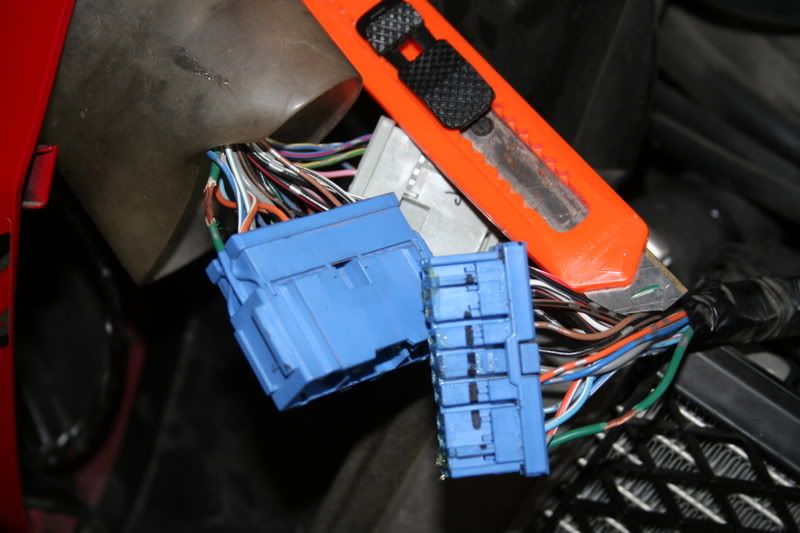
First thing - locate the blue connector under the left side fairing, hidden inside a crappy little plastic cover.
Locte the green wires on both sides of the connector. These are the wires you need to work with. The goal is to create an additional path ACROSS the blue connector - as well as create an additional ground location for these wires.
I used a knife to carefully shave off a small (1 cm) length of green sheathing from each green wire - on each side of the blue connector.
Next - I needed to find a secondary ground location to attach the soon to be created "jumper" wire. Found the 8 mm bolt that attached to the frame - just under the left of the gas tank. With that located, I needed to create the jumper wire. HEre's what I made:
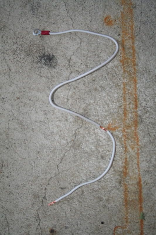
Wire is 14 gauge, and has a ring terminal crimped onto the end to attach to the frame near the left side of the gas tank. I stripped out a small section of sheathing to make the contact with the aft side of the blue connector (green wire) and the end piece to connect to the forward green wire.
Next - I used some crimp connectors to attach the white Jumper wire to the already exposed copper inside the green wires. Its basic stuff - but it worked great:
Once I was sure that the connections were super tight - I wrapped them in electric tape, double layers. All thats left in the process is to put the fairing back on.
HOpe this helps explain how this fix can be accomplished with basic tools, and minimal expense. Might have been a $2.00 fix.
It is not a difficult task to complete - and even if your blue connector with green wires isn't "bad" why wait till it goes bad and strands you?
-
1
-
-
DAmn - that sucks! Sorry to hear you wrecked.
If its any consolation - I have a left 5th Gen Signal - but I'm sure shipping might be a bit of a beeeatch...... (Anyone in North America heading for Aus soon?)
-
Helped Banshee install Radars Sliders on the 99 Yellow beauty today. Things went really well. Radars product is amazing... Super easy to do on a 5th gen.
Banshee will post up photos of the results.....
Good stuff Darren! :thumbsup:
-
awesome stuff!!! but why go to all that trouble to have an engine WHINE at you ?
:goofy:
-
Wow! At first the small nuts were driving me nuts, but after a few minutes of taking a breath (and a beer) I figured out the best way to put the plate on, and man it looks gooood!
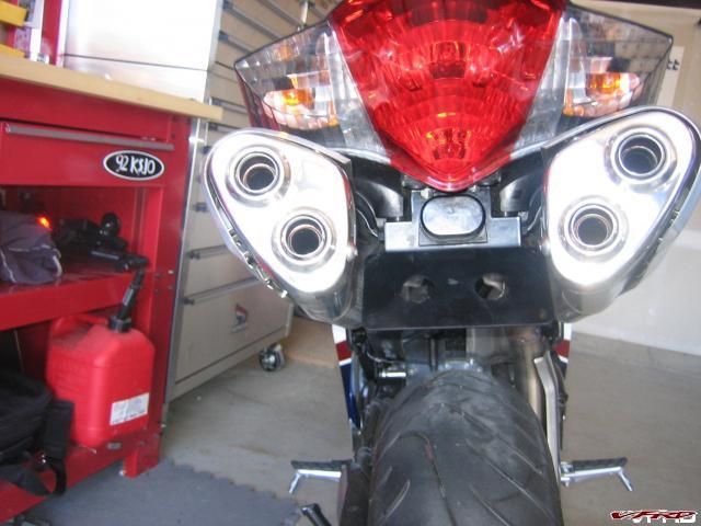
Word of advice, when you are trying to mount the license plate light onto the Fender Elim, I found that taking a rasp to the plastic and grinding down about 1/8 inch seemed to make the installation a bit easier. Regardless, the old fender is now in the 'Stock Box' in the garage in the event I ever need it.
Thanks Ken for such a nice product. If/When I ever decide to get some hardbags, I'll look at your rear mount option. :thumbsup:
EDIT: Some more pics of it in my Gallery, I should have made a pictorial for the actual install, but it was dark in my garage :pissed:
Cool - glad things worked out.
Next batch of Eliminators to be ready for Sale Wednesday!
-
Darn it Ken: Nick and I were talking at TexasMac about how I wanted to hear a Stebel horn sometime but didn't know who had one. I wanted a demo. :pissed:
Sorry Marty - I blew the damn thing at just about everyone near me - sorry you missed it. Ok - I'll load up and head back. Be there in about 20 hours....... :thumbsup:
Titanium Camera Mount! (huge Pics, Sorry)
in Modifications
Posted
Seb - cool idea!
SLammer - you have a point there.......
YOu could use my Solo Rack as the base to mount your block to. It is solid as a rock.
Additionally - the Solo Rack would be ideal for the rear facing views.