IntAceptor
-
Posts
209 -
Joined
-
Last visited
Content Type
Forums
Profiles
Gallery
Blogs
Downloads
Events
Everything posted by IntAceptor
-
From the album: IntA's Album
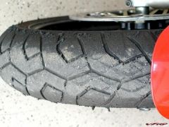
I went to a track day at Talladega in Alabama on Monday sponsored by eastTNriders.com. The day was near perfect and the rain held off except for one session that I was riding that amounted to a few drops on my face shield yet just enough to make us take note. Just as fast as it came on it stopped and all was well again. I was the only VFR on the track and as usual had a hard time keeping the 600's and larger in check down the straights but in the corners things got a bit even again. The one thing that was interesting and mentionable was that the guys I went with were running Michelin Powers and had fantastic traction and in a few cases were on their 6th track day on the same tire. These guys are no slouches when it comes to fast stuff and they are pushing to the limits 100% of the time. It is amazing how those tires are holding up. -
From the album: IntA's Album
-
From the album: IntA's Album
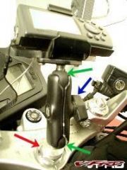
I took a piece of aluminum stock and tapered it to fit the steering stem hole, drilled and tapped a hole in the stock and screwed in the mounting ball. The unit is linked by the standard RAM mount. -
From the album: IntA's Album
-
After 27 K miles, I decided it was time to replace my chain (hey, good cleanings and lots of lube). ?So WITHOUT having the fancy chain breaker / flaring tool, I forged on knowing with a bit of creativity I could do the job. ?I shagged a chain / sprocket kit last Christmas and now I was going put it into use. I removed the rear wheel and the side plate that holds the clutch actuator and the speed sensor pick up unit. ?There are 4 ? 8MM bolts holding the plate on with two the same length and the other two shorter. ?One by just a little bit and the other by a lot. ?Remember which is which so the unit goes back on easily. I cleaned all the road gunk out of the front sproket housing and moved on to the next step. Break loose both the front and rear sprocket holding nuts with the bike in gear before taking off the old chain. ?That makes the job easier. Here is a picture of my two chain breakers. ?I used the big red one but the smaller one would work fine also. ?Move the chain adjuster on the rear hub as far forward as it will go so the new chain diesn't fight you going on. I greased up the teeth on the front sprocket driving shaft before putting on the front sprocket. The new chain was threaded in place and the new master link was ready for installation. Put two ?O? rings on first and then grease the master link pins as well as the holes in the new chain?s links they will be going into. ?Then install it and put two more ?O? rings on the pins once the master link is in place. I measured the chain?s width at across a number of side plates with a dial caliper and came up with an average figure of .890 inch. ?That is how far I wanted to press the new side plate on to the pins and no futher. I thought about a variety of ?pressing tools? that included ?C? clamps, pipe clamps, a mini-vise but ultimately settled on a large pair of curved jaw vise grips. ?I feel that a good wood pipe clamp (that is used to clamp sections of wood together) would work as well as the vise grips but you would have to use a template to fit the width of ?the link you are working with so the wider jaws wouldn?t contact the neighbor links. The side plate started on nicely but you could only go to the point where the pins get to the far end of the side plate until the vise grip jaws interfere with pressing it on any further. ?At that point I took a piece of steel I had, drilled holes in it that matched the holes in the side plate but larger and continued pressing the plate on the pins by being sure the vise grips were parallel and turning them no more than ? turn tighter each squeeze. I proceeded very slowly and took measurements as the plate was squeezed on. ?When I got to .890 I stopped. ?Now the plate was on the same distance as the others. The next hurtle was to come up with a means of flaring the pins. I took a ? inch bolt and ground the end off at about a 60 degree angle and cut it off to about 3/8 inch long. The angled end was placed in the end of the master link pin and the vise grips were put back to use to squeeze the fabricated tip into the pin. ?I was always careful to be sure the opposite end of the vise grips were contacting the far end of the pin only and not the opposite side plate while doing any squeezing. ?This process started the flare at the end of the pin that would insure the side plate stayed in place. ?I then traded the angled bolt for a ball bearing which further flared the pin. The flare doesn?t have to be huge. ?Just enough to stop the side plate from moving from the position you set it in. ?The plate itself is a very tight machine fit and it doesn?t take much at all to keep it in place. The clutch side plate was then put back into position. The speed sensor pick up looks like a 6 point socket that fits over the front sprocket securing nut and spins along with that nut. ?I noticed the nut didn?t seat into it as far as I would like it to so I took the clutch side plate back off, removed the sprocket nut and added another washer to the sprocket nut to set it out a bit further so it would sit in the sensor a bit deeper. ?Probably not necessary but it just made me feel better. Everything was re-composed, all bolts torqued to spec, the chain was adjusted and off I rode into the sunset. ?It was like riding a new bike.
-
>>>>>You have any pictures? ?Interesting I take it you had the tire off, so that you could raise the swing arm? <<<<< Naw, I was going to take some pictures but once I got started, it felt so good, I just couldn't stop. I kept the wheel and tire on and raised the swing arm by lifting the whole affair far up into the wheel well then putting 2X4's under the tire to keep it chocked up. Remember, I had the shock completely disconnected when I did the lifting and when the swing arm hole that the shock went through was about horizontal or maybe a little higher, I was able to wiggle the shock out and get the other one in.
-
Got me a Fox Twin Clicker and jumped on the Slammer's installation of his Ohlins to get some ideas. He took off the rear wheel, gas tank and the exhaust system to get at the nuts and bolts that needed to be removed, cleaned and painted the exhaust headers and lubed everything up before re-assembly. ?Absolutely the proper way to do it, hands down. Now not to slam our Slammer (for he is of mechanical mind and stout heart ?:bow: ) and being that I am going for a ride today and had to get it done last night, I decided to opt for a lazy man's way of doing this. ?I did want to clean everything, which I did, and I did want to lube everything which I did also, BUT I didn't want to decompose the bike in the process. ?Time restraints didn't allow for it. Soooooo ?--- ?with a beer in hand ?:wheel: , I sat back for about 5 minutes and just looked at the situation. ?When the effect of the mostly gone can of beer took hold on the one or two remaining neurons in the gray matter ?:idea:, the light came on. Hey, said I, this can be done without taking off the rear wheel, tank, and exhaust ?------ ?Maybe. So in I went. ?With bike on centerstand I supported the rear wheel with a block of wood. ?Not lifted, just supported. I took out the bolt that holds the bottom eye of the OEM shock and then removed the other two bolts and the tri-angular side brackets that the shock and the linkage couple together with. ?I also removed the pivot collar (the dog bone looking arm that comes off the back of the engine). The tank was raised but not removed (shaken not stirred) and all the nuts bolts and rubber pads up there were taken out of the way so I could get to the nut holding the top of the shock. ?That came off easily. There was not enough room to maneuver the shock out from between the swing arm and the exhaust canister with the swing arm in the lowered position it was in so I lifted the back wheel way up into the wheel-well now that the shock was not attached. ?I chocked the wheel in that position and the old shock nearly fell out. The upper "U" bracket that holds the top of the OEM shock had to be opened up about .050" to fit the new shock's bushing but that was no biggie. So far so good. I then threaded the Fox's remote reservoir up through the hole and out through the left side between the sub-frame and the chain guard for final mounting behind the passenger peg. ?The shock itself followed and I tightened the upper bolt to the frame to hold it in place. I then cleaned and lubed all the bushings and needle bearings at all the pivot points in the lower section. ?All the places where bolts go through have bushings and when removed, there are needle bearings in the housings they reside in. The side plates went back on but in order to get the bolt into the pivot collar you have to let the rear wheel down to meet it. ?That too was no biggie and when I was convinced I tightened up all the bolts and had the reservoir mounted I re-composed the rest of the bike dropping nuts and washers into the frame as I went (is there any other way to do it?) ?:doh: and with the help of an inquisitive wife, set the rider sag to a little over and inch as a starting point. If my exhaust headers were in need of it, I would have painted them too but they weren't too bad. This was the LAZY boys way of installing a Fox shock. ?I can't say if the other makes would fit in as easy as the Fox but you can give it a try and report back.