

BiKenG
-
Posts
646 -
Joined
-
Last visited
-
Days Won
6
Content Type
Forums
Profiles
Gallery
Blogs
Downloads
Events
Posts posted by BiKenG
-
-
On 7/30/2018 at 2:52 PM, bdouvill said:
So I guess there's a difference in the engine accessories. Do you know if that specific part of 4th gen engine would make is way on 3rg gen engine as a direct swap? I haven't look at the microfiches yet.
I'm 99% certain the 4th Gen parts could be used on a 3rd Gen and I'm 100% certain that one way or another, using 4th Gen and/or similar parts from other Hondas, you'd be able to get a Honda electronic speedo drive on a 3rd Gen.
But there are other ways to pick up a speed signal with a small sensor attached by the wheel and picking up from a moving part, often a special disc bolt. The best method rather depends on what the ultimate goal is and what dash you intend to be using.
-
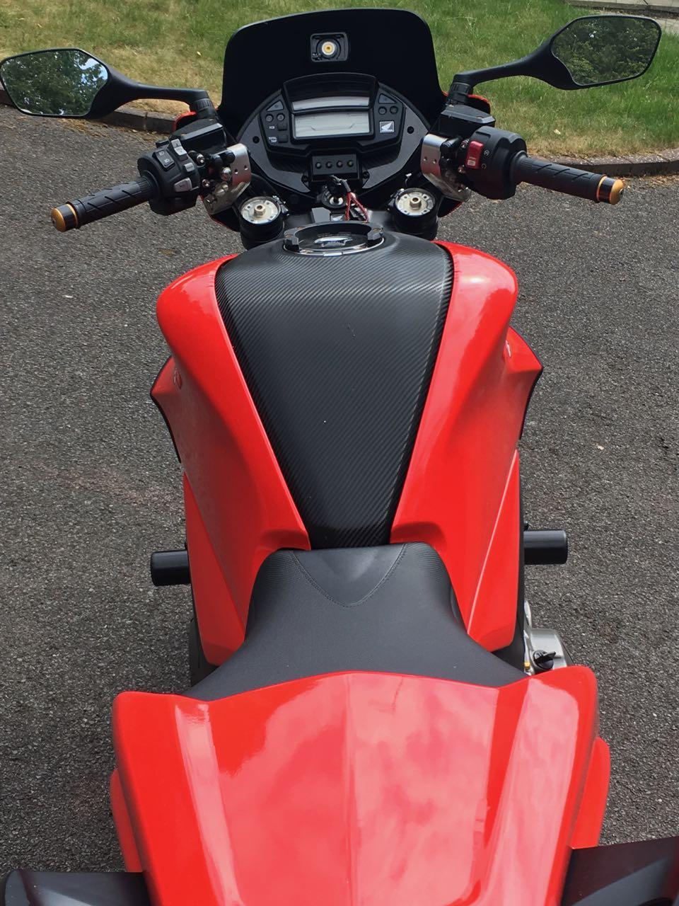
Carbon fibre finish vinyl wrap can be very effective when carefully applied 🙂
-
The main ECU and ABS ECU do not talk to each other. The ABS ECU conditions the speed pulse signals from the Wheel Speed Sensors and passes them on to the main ECU, but there is no other connection. The main ECU is unaware of anything to do with the ABS.
-
12 hours ago, RC1237V said:
Those carbon side covers are tits, where did you get them?
Apart from the dash, the only carbon fibre on the bike shields the wheels. 😀
-
6 minutes ago, Grum said:
...Can assure you that the 4 VFRs I've purchased from new are certainly stamped with month and year manufactured, surprised to hear that at least date and month of manufacture is not standard. As per below 7/14 for my 8gen.
Well I've never seen the actual manufacturing date marked on the plate like that. Normally you have to go cap in hand to the manufacturer to get that information and Honda UK want £30 (each bike) to do that and provide a dating certificate (sometimes needed for 'Historic' vehicle classification).
In the US there's usually a large 4 digit year shown, but that's the model year. I have seen this on bikes in the UK, but I'm not now sure what the actual requirement is here. I just checked two 2012 bikes and can see no plate at all, although I have no recollection of removing them. Where's the plate supposed to be on a 2012 VFR1200F?
I like the idea of the month and year of manufacture stamped on all plates. Should be mandatory in all markets. It would really help as the bike ages and also provide a clear understanding to any potential purchaser of how old the bike is, irrespective of when it may have been first registered and used (which is always stated on the registration doc). Not that dealers ever are ever economical with the truth about that. 😀
-
7 minutes ago, Grum said:
Month and year manufactured should be stamped on the compliance plate!
Different markets have different requirements for that and in any case, only state the model year which is not necessarily the same as year of manufacture as the latter is often in the previous year.
Regarding a 2013 manufactured bike (so probably a 2014 model year) being sold in 2017, that doesn't surprise me at all with this model.
-
15 hours ago, RC1237V said:
Nice job!
Any idea on the amount of weight reduction?
No, apart from a wild guess. I'd be interested in weighing it to compare. Would need to think of a way to do that and also to obtain a standard VFR1200F to weigh at the same time (well, not simultaneously of course 🙂 ) to obtain a true comparison.
-
I would disagree with the above opinions. I think they are a fantastic benefit and enable you to ride better. To ignore them or condemn them as only useful for idiots who have no right to be riding a bike is either ignorant or simply missing the point, although I'm not suggesting the previous replies fall into that category.
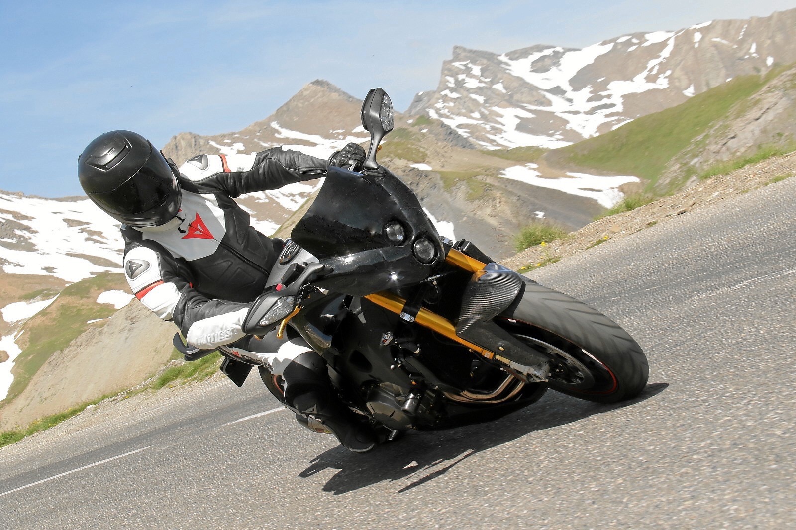
A GPI is most useful for indicating top gear and first. As the others have mentioned, mostly in between it is not so useful, however it can still be handy on occasions. I find it particularly useful when dashing between Alpine hairpins which involves a lot of changing up and down the box and without a GPI it is easy to lose track of which gear you are in. That's not to say it is required to be able to ride, but when rapidly shifting down from e.g. top into the tight hairpin that you know will require the use of first gear, it is handy to be able to glance down and so know when you hit first and can control when you make that final shift and also don't try to change down any further which can cause excessive speed into the corner if you get it wrong, or bad wheel hopping when you inadvertently change down too many gears at once.
None of this is really necessary on track when you are repeatedly performing the same actions and changing gear at recognised places on the track, but when riding rapidly on unfamiliar roads and that require rapid changes of speed and gear, a GPI is most definitely extremely useful. If you do not find this to be the case, then you are not making the best use of the information available to you.
-
 2
2
-
-
13 minutes ago, JZH said:
Don't you need a special charger for these batteries? I mean, I couldn't use my Optimate, right?
Ciao,
Correct. A standard battery charger is not really suitable. But you can get battery 'tenders' that can do both types and I now have a couple of those (and I can get more). I guess I'll slowly transition to all dual type devices, but for now those 2 will suffice. Don't forget, the lithium batteries hold their charge MUCH better than traditional lead acid types. The theory is you don't actually need a battery tender as they'll last for months without being used. I've not tested this so cannot comment, but reports I've read indicate it is true.
It still amazes me that such a small battery which seems to weigh nothing spins over and starts the VFR1200 at least as well as the OEM battery. A great example of a good use of new technology. See, I'm not a complete luddite. 😀
-
1
-
-
Sad to say, I've not visited Australia, but I've seen pictures of great scenery. Certainly less crowded than Europe and the UK in particular.
I have my 4th and 5th gen projects too. But the eVo4 is my longer distance bike. Although I still fancy a CrossTourer as well. Oh and ...
-
9 hours ago, keef said:
Can you lower the headlight a few inches?
Not really as it sits down on the original fairing stay. Well it could be done by making a completely new bracket, but why? I think it looks the right height and does the job it is intended to do, keeping the bulk of the wind off me and allowing comfortable riding at the desired speeds. Any lower and I'd just be fighting more wind pressure.
Personally I think any lower would not look right. But feel free to do your own conversion, with the screen in whatever position you desire. 😀
My main use for this bike is European 'touring'. Relaxed and easy mile munching but terrific in the twisties too. My FireFighter (damn, I need to change its name) is the ultimate weapon in the Alps, but although the eVo4 is initially noticeably heavier slinging it through the Alpine hairpins, that feeling soon vanishes and it is at least as rewarding. Also doesn't require any chain adjustment at any time during the trip. 😀
-
On 7/10/2018 at 3:49 PM, irishrOy said:
...I got a few questions, hope you don't mind
Not at all.
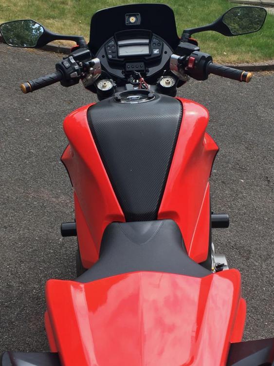
How did you get your hands on such a nice front fairing, though? Did you make it on your own, or is there a shop that sells fairings that fit on most bikes?
It's the Alien by Puig. I chose it because it was the look I wanted and only later discovered I could mount it to the original front fairing bracket with the original mirrors, although I raised them slightly with a 10mm spacer. Rear view is good even though they look quite low.
I'm intending to replace the projector light units with LED, but not found anything suitable yet. I have an idea though so watch this space.
I think I may have bought the last 2 Aliens though as Puig has discontinued that fairing/screen. It's always the same, I discover something I want just as the manufacturer decides to discontinue it.
Any different sounds from the engine-mechanics itself?
Not that I'm aware of. The engine is quite quiet mechanically and the exhaust is surprisingly quiet despite the very short muffler (from a ZX-10R). In fact it makes a lovely V4 sound. Very smooth and mellow. Ask Mohawk, he's followed me.
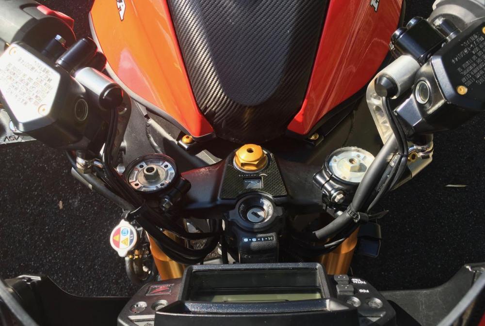
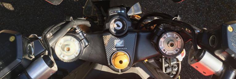
What is the yellow stuff between the frame and the tank?
What I think you're referring to is gold aluminium mesh which covers the air intakes into the airbox.
Is there an option you might post a video of your bike while running? 😄
That's a possibility, but right now I think the exhaust might need re-packing. It has about 7-8K miles on it so it quite likely does and I thought it was sounding a bit more raspy than usual on the last trip. I'll see. I might try and just record something anyway. I'll add it here when I do.
-
1
-
-
1 hour ago, Spreeweiler said:
Nice, these streetfighters just need machine gun mounts and retractable bayonets!!!


That's why in general I tend to not use the term 'Streetfighter'. I prefer 'naked roadster' or something similar.
The original streetfighters were stripped down (often after a crash) and the intention was for it to look scary. But I just want a naked version of bikes I like, that Honda don't do as standard. Not intended to be stunters, or scary in any way. Just with a more upright and comfortable riding position and not covered in plastic. When I started riding bikes there were virtually no fairings on road bikes. I followed the 'faster is better' mantra with sportsbikes for years, but eventually grew out of that. I no longer feel the desire to try and wrap myself around the petrol tank and always having to don full leathers before going for a ride. I guess most here feel similarly, that's why we like the VFR, but I like to go further and shed the plastics.
But 'streetfighter'? Nah. 😀
-
I can confirm that a Shorai LFX14L2 - BS12 battery is man enough for the VFR1200.
This is such a diddly small little battery and so light it seems like it will float away, but it turns over and starts my VFR1200F as well as the original lead acid ever did. This battery is even smaller than the battery normally used in the FireBlade and CRF450X, but as I said, works great.
Caveat.
It is now summer and lithium batteries are known to struggle more when cold. I've no idea how much it would be affected, but it can be overcome by warming the battery slightly first (just turn on headlights for a short while) and in any case, I don't ride when it's that cold so I don't care. 😁
Also, if you're trying to run loads of accessories you may struggle. Having said that, you shouldn't be trying to run more than the generator can cope with in normal running anyway. If you are, then ride time will be limited whatever size battery you use. So I don't really see this as a problem.
Anyway, for my usage there are no such issues and it's not only a great way to save weight, but the space it gains allows me to also carry spare fuses, repair tape and puncture repair kit, all in less overall space than taken up by the original battery.
The above is not simply self advertising, but personal experience. However, I am able to supply Shorai batteries at a great price to members although probably only makes sense in the UK.
Anyone want a good original VFR1200F battery for the cost of shipping, just let me know.
-
1
-
-
I stuck to just quoting miles/litre as that avoids the US/Imp. gallon confusion. I also quite like it and find myself thinking in those units.
As I mentioned, it must be kept in mind that pre 2012 bikes relied on the sender output to determine low fuel level. But this is not accurate and so in 2012 they added the low fuel level sensor like (all that I know) other Hondas. This works entirely independently from the main sender and is quite accurate.
I have the VFR1200X Crosstourer dash on my bike and the fuel display is not yet matched to the F sender output. The display basically is not getting the full range it expects so drops quicker from full and still shows at least 2 bars when low fuel level is detected. But what is interesting is that as soon as that low fuel level is detected (due to the low fuel level sensor), even though the dash might still be showing 3 bars, the display immediately changes to a single flashing bar. So that low fuel level warning definitely overrides whatever the main level sender was indicating prior to the low level being detected.
-
Well the range of the sender unit is unlikely to have changed, but I guess it's possible the arm could become bent and shift the whole output, up or down.
It's also worth remembering that prior to 2012 there was NO low fuel sensor. They just relied on the main level sender output to decide when to display the low level warning in the dash. But this was rather unreliable so they fitted an independent low level sensor from 2012 onwards. This required a change to the tank and also the dash. If they have become mixed up then you might get unexpected results.
The first check would be to measure the full and empty readings of the main sensor. They should be within the specs as stated in the manual, that's 12-14 and 119-121 Ohms respectively. As you can see, mine are slap bang in the middle at both ends. So I know my sender is good.
-
25 minutes ago, adkfinn said:
It is a nice bike and I like it as well, but if the work gives you a sense of satisfaction and you appreciate the changes that is all that matters.
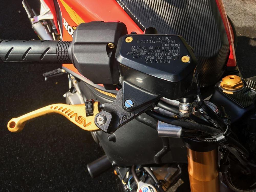
On that note: Do you mind sharing details on the bar ends and reservoir cover screws? I have been looking for hex head screws in red for my bike but haven't been able to find any.
The reservoir cover screws are just gold anodised Al. countersunk Allen screw, M4 if memory serves correctly. If not available from eBay then I almost certainly obtained them from Pro-Bolt, a UK supplier of fancy nuts and bolts. Great stuff, but they're not cheap.
The bar ends were cheap off eBay and I machined them to fit the ends of my bars. They originally used basic rubber blocks that expanded inside the bars as you tightened the screws (cheap and nasty), but now are screwed directly into the bar heaters and both held firmly and securely in place. The plugs on the inner ends of the bars I made in either Delrin or nylon, I forget which but I think the former.
Since you likely are using standard bars, I suggest the R&G bar ends. In stainless steel with a black plastic cap at the end. They are made to fit Honda bars and are screwed into the anti vibration weights as standard bar ends do, but I think they look much nicer and in theory if you drop the bike and just damage the plastic end, you wouldn't need to replace the entire metal fitting. I say "in theory" as the only time I've tested this I managed to wear away the plastic and a big corner off the stainless so had to replace the entire assembly, but that was my fault, not R&G's.
-
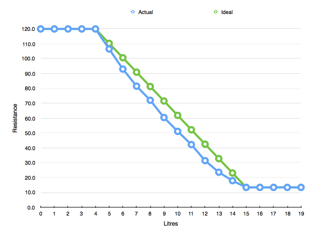
Much has been talked about the fuel capacity of the VFR1200F, but in order to fully understand how the fuel level sender is operating, I conducted a test with my 2012.
Starting with a completely empty tank (i.e. dry, not just unable to pump any more) I measured the sender resistance and then added fuel litre by litre, measuring the sender's resistance at each step. At 19 litres it is completely full, up to the very top and some way above Honda's recommended maximum level, but in my opinion there's no need to take any notice of Honda in this instance. There's at least an extra litre that can be squeezed in after the level has reached the bottom of the anti splash ring around the filler neck. Honda say "no more", but why. What's gonna happen. The worst is that it might drip a bit out the overflow (although never had that myself) and the best is that you gain additional range. Anyway, whatever the rights or wrongs of this, it's what I measured.
In fact it's nicely symmetrical then as there are 4 litres at the top and also 4 at the bottom that do not change the sender's output since it is already at the ends of its travel. It is also far more linear than I expected. I added an 'Ideal' straight line to the chart so you can see, but the reality is not as far out as one might expect.
I also discovered that the low level warning came on at 180 miles with about 3.5L remaining in the tank, so I was able to squeeze in (i.e. right to the very top) 15.5 L. That represents about 11.5 miles/litre average which is quite acceptable IMO.
Hope others will find this of interest.

-
2
-
-
1 hour ago, FJ12Ryder said:
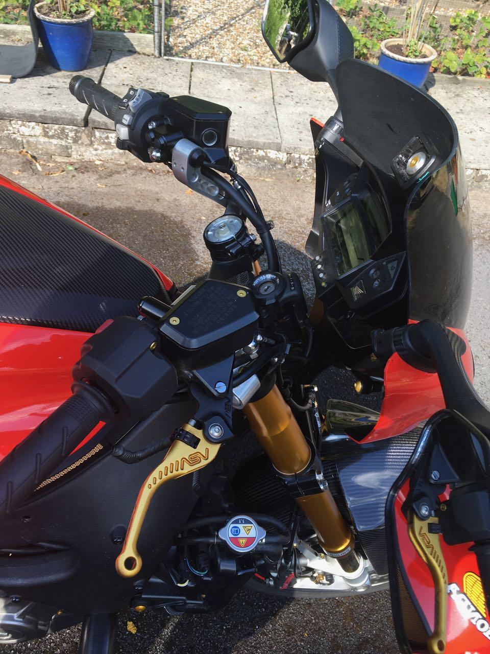
Are those without the cables? Doesn't seem to look that much different than with cables. Lots of stuff coming out.
I guess I was thinking you wouldn't see anything, but there's still wires to run.
Yes of course there's electrical cables (and hydraulic hose on clutch side), as before and no way to dispense with those. In any case, they're no bother really as they can be tucked in and strapped nice and tight and out of the way. Throttle (and clutch) cables need long smooth curves that means they stick out a long way and flap about and need a lot of clearance to allow the bars to turn.
Having said that, electrical cables can be run through the bars which can look even neater, but not only is it a real faff to do, but it's a total PIA when you need to work on them or take the bars off etc. That's simply not worth the effort. Throttle and clutch cables are what needs to be eliminated IMO. Others will think differently, but that's up to them and not my concern. This is my bike and I like it. 😀
-
On 7/11/2018 at 9:15 AM, BiKenG said:
I'll add some more pictures of the cables etc.

-
8 hours ago, FJ12Ryder said:
Sounds pretty cool, but I can't help but note that if you notice throttle changes when you turn the bars, you've got
it adjusted wrong.
Well whatever the adjustment, it changes as you turn the bars. Just a fact of using Bowden cables. Whether you notice will depend on a number of factors, but particularly so when you prefer to have minimal slack in the cables. I hate a 'loose' throttle, i.e. with a lot of slack. Makes it much more difficult to be smooth when transitioning from off throttle to on throttle and vice versa. But it's impossible to have no slack when riding straight as when you turn the bars, the throttle will open slightly. To avoid that, you have to allow more slack. So you cannot achieve optimum cable adjustment under all conditions.
Those long throttle cables can also interfere with other parts of the bike as the bars are turned. I was unable to mount my iPhone (for Sat Nav duties) where I wanted to due to the clearance required for the cables when turning. In the end I mounted it higher up and out the way which is actually better, but not always possible on other bikes. For the same reason I prefer hydraulic clutch operation as the hose can be routed almost anywhere, whereas a cable needs a smooth arc and of course can catch when trying to turn the bars.
Whether any of this actually bothers anyone is a personal matter, but it's always irritated me. Particularly since the introduction of Drive By Wire on cars as I immediately saw the possibilities for using twist-grip sensors on a bike. Then when Honda finally get around to using RBW, they use cables. Aaarrgghhh! 😧
I'll add some more pictures of the cables etc.
-
7 hours ago, St. Stephen said:
...Oh, and a couple more photos please?
I did show more pics in another thread. But here's a link to the whole project if you want to have a look:-
-
1
-
-
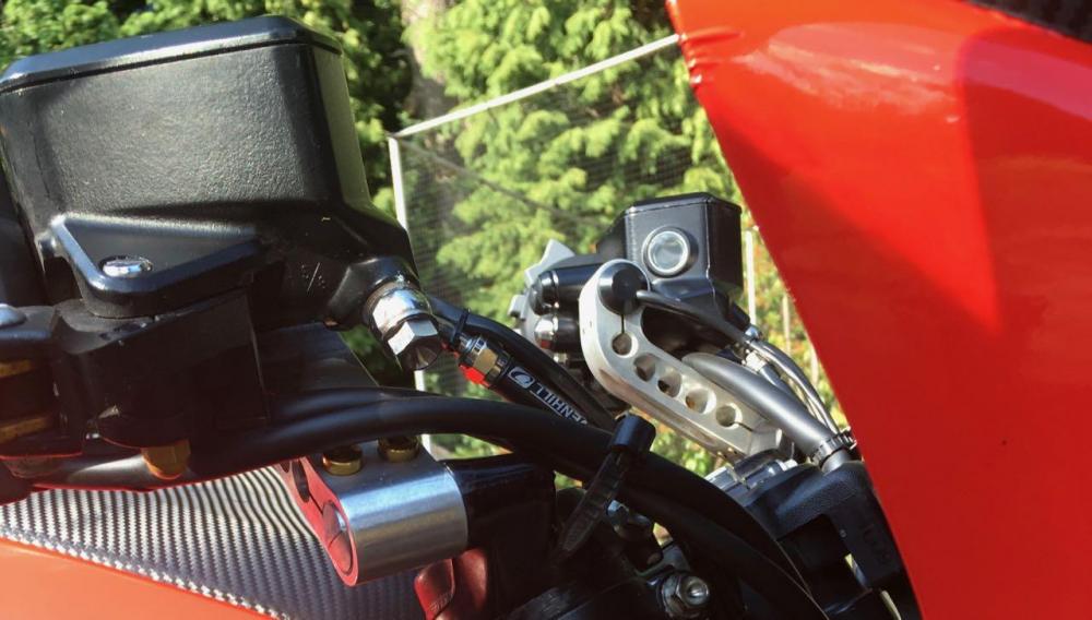
Part of Phase 3 of my eVo4 project was to try and eliminate the throttle cables. I realise there will be some who have no problem with throttle cables and can't see any point to my efforts, but I don't care. As far as I'm concerned they get in the way, their adjustment varies as you turn the bars and they have no place on a bike that is in fact Ride By Wire. Honda are not the only manufacturer to have done this as the Aprilia Tuono (at least the later ones) are RBW but until very recently also still have cables.
Why Honda decided to use cables I have no firm idea. The most likely reason was suggested to me by a dealer who thought Honda were just being mindful of the conservative nature of motorcyclists and only gradually introducing the concept of RBW and missing throttle cables. So first we get just RBW with cables, then later drop the cables. This is certainly typical of Honda thinking, but as we know, they never changed the VFR1200 in this regard (or any other in fact) and other manufacturers introduced RBW with twist-grip sensors and no one seemed to have a problem with those. Anyway...
I don't like the cables and wanted to replace that system with an integrated twist-grip sensor. I studied the BMW and then the KTM systems, but their output didn't match what the VFR's ECU was expecting so some sort of converter would be required and I felt that was a step too far as I figured eventually, there'd be a Honda part that would do the job.
First came the RCV thingy, but any parts for that would undoubtedly be a stratospheric price (even more than normal). Eventually in 2017 we got the new FireBlade and checking its Service Manual revealed that despite its different sensor type, the output was in the same range as the VFR's. So although the VFR's TCP Sensor (cable driven, mounted on side of throttle bodies) is a simple variable resistor and the new CBR's twist-grip is a Hall Effect position sensor, they both do the same job. Two independent sensors (for reliability and error checking), a supply voltage and ground connection and the output signal which operates in the same voltage range on both bikes. Not totally surprising really as Honda's designers would be working to the same parameters and the same output voltage ranges would make sense. So...
As soon as the new parts became available in 2017, I took a chance and ordered a new 2017 CBR1000RR FireBlade twist-grip and also the LH switch so they would match and I could use the additional buttons for the Cruise Control. Once received I set to modifying things as necessary. This was relatively easy for the twist-grip. There are 6 wires - power, ground and signal for each of the 2 sensors so it just required matching them up between the new twist-grip and the VFR's loom. The LH switch was much more complicated, but not relevant to this thread.
Unfortunately, health issues brought this project to a halt last year and I only got it completed a few weeks ago. However, I can report that it works. Perfectly. YAY!
I've just returned from an approx. 1000 mile trip without a throttle cable in sight (well, not on my bike 😀) and nary a hiccup. By which I mean that the throttle control has been perfect. I could say that you couldn't tell the difference from a std. VFR1200, but that would diminish the pleasure I get from not seeing those cables flapping about. Truth is there is NOTHING negative I can report about this. The throttle operation is smooth and very direct and of course never varies as you turn the bars etc. Just perfect all the time. I also really like the single combined Kill switch and Start button and the aforementioned buttons on the LHS which are perfect for my needs, although I still added some additional very neat buttons by Motone on the RHS for the handlebar heaters and on the LHS for Cruise Control memory functions.
So, anyone who like me would like to dispense with the throttle cables on their VFR1200, a 2017 FireBlade's twist-grip can be used to do so. I expect the latest Africa Twin twist-grip could also be used, but I've not looked into that.
I do love it when a plan comes together 😁
-
6
-
-
Just seen this and wondered about the final outcome. I cannot now remember the cam cover to head seal on the VFR1200, but I do remember many years ago after a service on an RVT1000 (RC51 / SP-1) when I noticed it smoking on the overrun. As has been mentioned above, it was a missing PAIR oil seal. Allows oil to get sucked into the exhaust although I don't recall any oil leaking out of the engine. Once I took the cam cover off I could spot that the seal was missing and once replaced and all back together, no more problem.
So that sounds like the exact same problem.


Triumph Eccentric Swap (pic heavy) (not complete)
in Modifications
Posted
Fixing picture links would be great.