BonemanVFR
-
Posts
41 -
Joined
-
Last visited
BonemanVFR's Achievements
")


-
Mounted my FZ1 Fuse Block under the seat next to the rear brake fluid reservoir. Just fit! (2008 ABS VFR)
-
I added one more....
-
Stebel Nautilus Horn FTW!!!! 128db of train derailing goodness!!! I've used these on all my bikes. I managed a pretty slick installation on my VFR by separating the horn from the air compressor, placing them inside the right front faring and using tubing to reconnect the two. Full write up on my VFR site here: http://bonemanvfr.com/Mods/stebel.html Here's how it sounds! https://www.youtube.com/watch?v=k8EXRVYNXzI
-
I just posted a reply in another thread about TechSpec tank grips. Great product. You can purchase pre-cut shapes or get blank sheets and make your own! http://www.vfrdiscussion.com/forum/index.php/topic/79124-techspec-tank-pads-or-similar/?p=966057
-
I've used TechSpec grips on my VFR and FZ6. Love the product and the company is great to deal with and stand behind their product. Had a chunk de-laminate from the sticky backing after a year of use and they sent me a new sheet at no cost! I've used the thicker "Snake Skin" material as well as the thinner, easier to use "High Fusion" material. Both times I ordered blank sheets and designed my own tank pads to great success (was fun too). Here are my write-ups and installations for both. Feel free to contact me if you have any questions. http://www.bonemanfz6.com/Mods/mod_techspec.htm - Snake Skin application on my FZ6 http://bonemanvfr.com/Mods/techspec.html - High Fusion application on my VFR
-

6th Generation Stebel Installation - Clean and Simple
BonemanVFR replied to BonemanVFR's topic in Modifications
Mehhh, it's been working just fine. Guess I'll take my chances. -
6th Generation Stebel Installation - Clean and Simple
BonemanVFR replied to BonemanVFR's topic in Modifications
Little video of the horn in action: -
Just installed one this weekend. http://www.vfrdiscussion.com/forum/index.php/topic/69159-6th-generation-stebel-installation-clean-and-simple/
-
Spent a few hours today and got my Stebel Nautilus horn installed. After separating the compressor/motor unit from the horn, I found great spots for it inside the upper right side faring. I had a Stebel Nautilus horn on my FZ6 and I loved it. 139dB of derailing freight train goodness. Enough to wake up the most inattentive driver out there. For this installation I had to separate the motor/compressor from the horn unit. This is done by prying up on the compressor nipple that is inserted into the horn. The compressor was also glued to the plastic horn section, so some additional prying was needed to separate it. What you end up with is two pieces that makes mounting a little easier. Once separated, you simply use rubber tubing and a brass fitting in order to connect the compressor unit to the horn. I purchased a 5/16 rubber tubing and some barbed fittings from Home Depot. I mounted both the horn and the compressor unit in the right side front faring area. By mistake I had ended up taking the compressor unit apart (during my horn separation process). In doing so I found out that all it is is an electric motor that spins a shaft that goes to a 'fan' in the top that pushes air into the horn. So I didn't see any reason for the compressor unit to remain upright. For mounting the horn, I simply used some 3M double sided tape. For the compressor I used some 3M tape as well, but also drilled two holes through the black plastic and secured it with a cable tie. The Stebel comes with a relay and yes you will need one as it can draw up to 20amps!! I used the two existing wires going to the stock horn (light green w/silver dots = +12VDC activated by the horn button and dark green w/silver dots = Ground). I left the stock horn in place. Wiring for the relay is as follows: 85 - Ground 86 - Horn wire - light green w/silver dots = +12VDC activated by the horn button 87 - +12VDC switched (power when ignition is on) 30 - Horn compressor + - terminal on Horn compressor - Ground I hooked up 87 to my FZ1 Fuse Block and set it to switched power so only the horn will work when the ignition is on. You can also wire it so the horn will work with constant 12 VDC so it will work with the ignition off (user preference). I initially used a 7.5Amp fuse, but after 2 test blasts of the horn it blew the fuse. So I now have a 15 Amp fuse and that seems to work fine. - Boneman http://www.bonemanvf...ods/stebel.html
-
-
-
The ground is connected to the negative battery terminal - it's spliced into the negative wire already attached to the negative terminal for my SAE plug. I looked for a close switched power source to my fuseblock and the tail area was the closest and easy to check because fo the conenctor right there. I simply unplugged the connector and used a mutlimeter and checked the wires for 12VDC when the ignition was ON and no voltage when the ignition was OFF. I stripped and soldered on the wire for a solid connection.
-
THAT'S the picture I should have taken!! Thanks for posting it (great minds think alike...)
-
Date: April 22, 2011 Cost: $100.00 CDN (shipping included) Purchased: Fuzeblocks.com Manufacturer:Fuzeblocks.com Mod Time: 30 min Part No.: FZ1 I originally purchased the FZ1 Fuseblock back in May 2010 and it was originally destined for my FZ6 but I never got around to installing it (lucky for me). Fuzeblocks.com has designed a fuse block that is easy to install and fits into a small space. The on board relay offers the choice for any device to be switched on or off automatically with the vehicle or to be powered constantly. I found a decent place for it under the seat on the right hand side near the rear brake reservoir. I removed some of the plastic body work in order to make room for it. I found a decent place for it under the seat on the right hand side near the rear brake reservoir. I removed some of the plastic body work in order to make room for it. I wired it as follows: +12VDC - Direct from battery terminal, with an inline fuse (7.5 AMP) that also goes to my SAE plug for charging my battery (Battery Tender). Ground - Spliced into an existing ground wire that I had run to my SAE connector. +12VDC Switched - I tapped in to the the tail light wire so there is only power when the key is in the ON position (Brown/Blue wire). This will sure make it easy to add in additional electronics such as 12VDC outlet, heated grips & clothing, GPS, USB charger, etc. This write up is also on my site here: http://www.bonemanvf...m/Mods/fz1.html - Boneman
-
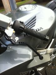
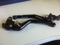
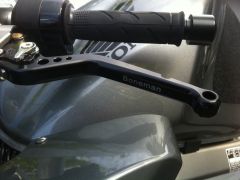
Got them installed and all I can say is this was $300 well spent! Thank you all who have previously posted about Helibars. The information was invalubale! Here is my little write up. Full details are also here on my site: Boneman's VFR Site - Helibars Date: April 22, 2011 Cost: $270.00 CDN (+ $30 USPS shipping + $37 Duty/taxes) Purchased: eBay - NEAFCycle Manufacturer: Helibar Mod Time: 1.5 hours Part No.: HB01003 After doing much research on Helibars on both VFRD and VFRWorld, I decided to invest the $300+ and hoped to increase my comfort level on the VFR. Not that the VFR is uncomfortable, but for my particular case I found I would get excessive neck/upper shoulder pain after about 45 minutes. This is primarily due to a previous mountain biking accident back in 2000 where I took a 5' drop onto my head and compressed my neck & spine. So I wanted to make the VFR more suitable for my personal comfort requirements. I've heard nothing but positive reviews regarding the Helibars so I decided to make the investment. Here are some helpful threads about Helibars: http://vfrworld.com/...eli-bars-2.html Installation Guide: This is a great installation guide done by one of the VFRWorld members (ottrod) and since he has already done a fantastic "How To" write up, I'm not going to go into any great detail on my installation. http://vfrworld.com/...re-you-try.html Installation was pretty straight forward. I found the Helibar instructions to be pretty straight forward and easy to follow. 1. Cutting off the Locator Tabs As per the instructions, I sued a Dremel rotary tool with a cutting disc and removed the tabs off the Brake and Clutch reservoirs. The clutch side only needed the forward tab removed. 2. Removing The Grips: There has been LOTS of discussion on how to go about removing the grips. All I did was use my air compressor with my air gun attachment and fired some air under the grip and presto, they swelled up like a balloon and off they came in about 4 seconds. To re-install the grips, a few squirts of hairspary did the trick. 3. Removing the Dampers: The most difficult part was getting the bar dampers out of the OEM handlebars, but they weren't that bad to get out. I spoke with my local Honda dealership before I started and he reassured me getting them out was pretty simple. I left the OEM bars on the bike to remove the damper units. I have a vice, but it's not attached to my bench, as well as the Honda tech also recommended leaving the bars on the bike. The trick to removing these is to make sure that you push in and twist the two little locking tabs. Once done, some pulling an wiggling will get the damper unit out. In the picture below you can see the locking collar 4. Installing the Helibars Installing the Helibars is straight forward. I found they are a very tight tolerance when trying to slide them over the fork tubes. I cleaned the tubes with mineral spirits and used mineral spirits like a lubricant to help the Helibars slide on. I measured the vertical position and decided on 0.275" from the top of the tubes to the top of the Helibar clamp. I adjusted both bars to what I felt was a comfortable position for me and aligned both. I checked that they did not interfere with hitting the tank on full lock and made sure none of the brake or throttle lines caught or got hung up on anything. I torqued the bolts to their specified 12ftlbs and went for a test ride. Initial Impressions: MONEY WELL SPENT!! Went for a little ride and no neck/back pain! Will have to try a long haul to feel the full benefits of these bars, but I already know this was a good decision for me and my VFR. - Boneman
-
Also available here on BonemanVFR.com: http://www.bonemanvf.../rgsliders.html Cost: $170.00 CAD (+ shipping) Purchased: http://www.rg-racing.com Manufacturer: R&G Racing Mod Time: 3 Hours Part No.: CP0073 Frame sliders were the first mod I ever did to my FZ6 and I figured I should also do them to my VFR. I did some research on various different brands and mounting applications and settled on the direct mount R&G frame sliders. These had good reviews from fellow VFR owners and I like the fact that they are directly attached to the engine mounting rod, which should hold up better in the event of a tip over. The R&G sliders also came with a new coolant overflow/fill bottle that has been modified to allow access to the engine bolt that is hidden behind the OEM bottle. With the R&G sliders you will have to drill/Dremmel a 1 1/8" hole in each side faring in order to install and mount them. This turns away a lot of people from purchasing these sliders, but I will walk you through some of the do's and don'ts of installing these sliders and you will find out that drilling isn't that bad after all. The R&G frame slider installation instructions (PDF) can be found here and on R&G's web site. R&G's "3D Installation Guide" does not really apply to this model of frame slider. First things first, remove the left and right body work and set aside. Your first step after that is going to be replacing the OEM coolant overflow/fill bottle with the new one supplied with the frame slider kit. Remove the OEM bottle and drain out the coolant into an container, then attach the R&G bottle and reconnect the hoses and pour the coolant back in. OEM Bottle R&G Bottle Here are the components of the R&G frame slider kit: x2 Bobbins, X2 spacers (1 short, 1 long), replacement threaded engine rod, x2 Ny-lok nuts, x2 washers Undo the nut on the right hand side of the OEM engine bar and remove nut. Then using the R&G bar, push the existing OEM bar out the left side at the same time sliding the R&G bar in. Now comes the fun! You need to mark the engine rod's location on the inside of each side faring. I used some wall tack putty and pressed it on the inside of each faring in the area of where the rod was going to make contact. This is going to give you the location of where to drill/dremmel your holes so take your time. Fit one faring on and loosely secure it with one or two of the faring bolts, then from the opposite side, use a hammer and tap the rod until it makes contact with the faring on the opposite side. I used vise grips on the rod (no on the threads) to wiggle the road back a bit so it wouldn't continue to contact the inside of the faring and mess up the mark it just made in the putty. Remove the faring and inspect the rod mark in the putty. Left Side Faring Marked rod location and center punched You will now notice that the location of the holes are probably in the worst possible spot on the entire faring! Use a center punch to mark the center of the rod's location and drill a small pilot hole (1/8" - 1/4"). Then re-fit the faring and check that you can see the center of the rod in the pilot hole. Now this is where I differed from the instructions a little. The R&G instructions and web site say to use a 28mm holesaw drill bit and even offer it for sale on their web site. So I bought one from Home Depot. After examining where the hole location was on the faring and all the complex contours in the area of where the hole needs to go, I came to the conclusion that there is no friggin way this 28mm holesaw bit was going to work!!! It was just going to make a mess and shred the crap out of my faring. So I opted to use my Dremmel with a grinding bit that did the job perfectly! 28mm Holesaw bit...no f'ing way! Dremmel rotary tool - the only way to go for this job! This process involve a lot of going slow and re-fitting and checking of each faring. My steps were: 1. Get the hole big enough so that the rod can fit through and refit the faring and secure faring with one or two bolts so that it is in the correct position. 2. Slide on one of the spacers onto the protruding rod and trace/mark it's diameter onto the faring 3. Un-mount the faring and continue Dremmeling away the material. 4. Take your time and keep re-checking. Once the hole is large enough for the spacer to fit through, STOP! That's as big as you need the hole to be. The "Hole" - Careful not to cut away the join in front of the rod! You can see why a Holesaw drill bit would not work Now you can refit your faring's (loose or fully re-mount them). The last step is to attach the bobbins onto the rod. This is where R&G instructions fail to provide you with some information of how this procedure ACTUALLY works. In their instructions, they very simply state, "Place washer and nut on either end and tighten bolt until you feel some compression from inside the protector. Turn a little more so that you feel the compression increase slightly.". Well one problem with that simple instruction... As you are attaching 2, Ny-lock nuts, one to each end of a threaded rod that freely spins, you will need TWO 19mm sockets, one on each bobbin, because as you tighten one Ny-lock nut, when the nylon thread portion starts to bind on the threads of the rod, it just spins the entire rod, so you don't end up tightening anything. So I ended up leaning across my VFR so I could grab each ratchet attached to the 19mm sockets and hold one nut steady as I tightened the other one. I alternated back and forth so each nut would thread into the rod evenly. Final results Very pleased with the final resultes and once the bobbins are in place, it is hard to even see the cut holes. The only down side I can see to this mod is that you now have to remove each slider/bobbin if you want to remove your body work. So it's an added pain in the hoop to an already annoying experience of removing the VFR body work. And remember, if you get stuck, don't be afraid to call for help and bring in the big guns!!! - Boneman