

MadScientist
-
Posts
642 -
Joined
-
Last visited
-
Days Won
6
Content Type
Forums
Profiles
Gallery
Blogs
Downloads
Events
Posts posted by MadScientist
-
-
PCV requires an ignition module. Not sure if it is even compatible with the VFR800 PCV either - doesn't show up as an additional purchase option.
-
 1
1
-
 1
1
-
-
3 hours ago, HighSideNZ said:
Looking good.
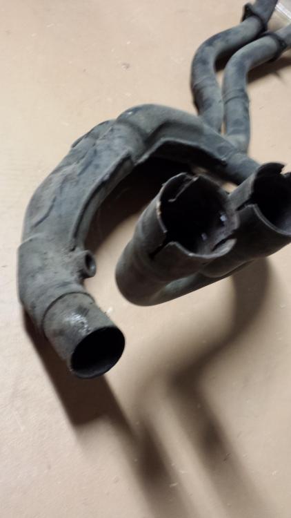
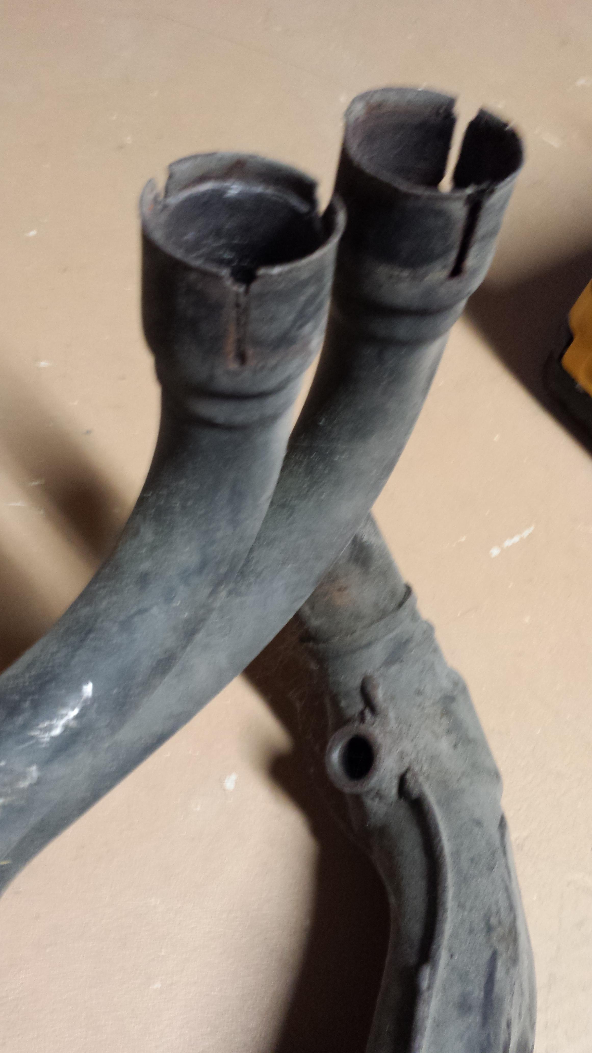
One thing that people may need to be aware of is the bottom O2 bung is quite level so you need to make sure it cannot get and hold water vapour during start/warm up, especially when being warmed up on the side stand.
Yeah, I was concerned about this too when I saw it. I think it will be ok, but I can't say for sure. Some of the pictures look worse than others, but the one looking forward from the rear tire edge (picture 5) is reassuring. The lower O2 sensor appears to be above the pipe midline and at a slight downward angle toward the tip, even on the sidestand. It is close either way, that's for sure.
Standing upright, it looks like there should be no issues. Just have to be careful with left lean until the exhaust is warmed up. Also, don't fill the exhaust with water when washing...
-
15 hours ago, WackenSS said:
Couple of vfr 400 nc-30 pics taken today.
Don't know the firing order but both banks merged together. These are feckkin jewels!They are most likely 180 degree cranks like the VFR, NC13-NC24 had 180 degree cranks, NC30 & 35 had 360 degree (like the RC30/45 and early VFxxxF).
Of course they could have later motor swaps or crank/cam swaps. IDK if the earlier engines are compatible with the later parts though.
-
1
-
-
Whoops, I just sent you and Lance a PM in case I missed something. Should have checked here first.
I still can't believe this is actually happening. Thanks for all your hard work!
-
I talked about this in the last thread. Basically there is no easy horsepower in filters, we are talking the last percent and trading something to get it.
Edit: Found it
-
1
-
-
Sorry it is not on the bike, but the landmarks on the old header will give a good idea.

-
1
-
-
Just to clarify, is the $95 passivation an extra cost above the initial price of the header?
Also, is Wade willing to add a 3rd O2 sensor bung after the final collector? If so, cost? We can discuss by PM if you want, but I figured others may want to know. Would be nice to have all welding done before passivation. I'm not sure that the 3rd O2 sensor bung is even necessary, so this is just academic at the moment.
-
Great job guys, I didn't realize you all were going to do additional R&D. Even though it didn't net any real gains, it is good to know that there isn't much left on the table with the original design. I've done a lot of HVAC pressure/flow analyses and have run into some unexpected situations in real world vs simulation vs fluid dynamics modelling. Matter of fact, you wouldn't believe how some simple things cause instability and pressure/flow oscillation. There is a lot that goes into managing interactions between turbulent and laminar flow regions.
Just out of curiosity, are the welds/joints in the taper regions smooth inside? A discontinuous change in diameter (step up or down) will lead to turbulence that disrupts the speed of the central laminar flow region. Of course exhaust gasses flow in pulses, which contrasts with the relatively steady pressure of HVAC air handling fans, so there may be factors I'm not aware of.
-
Thank you so much for posting the dyno graphs with the target AFRs, that helps me out for autotune. Looks like Attack Perf is running slightly richer than what I've set my Autotune target AFRs at. I'd be interested to see the full fuelling map, though it doesn't really apply to me (I'm running a 3 bar FPR). I don't suppose they gave you a full map of AFR targets...
On that PCV graph, now I see what other people are talking about with surging on the PCV. I wonder WTF is going on between 2000/01 ECUs and the PCV. I've had no such difficulties with my 98.
-
1
-
-
4 hours ago, sfdownhill said:
In pursuit of optimized tuning of the new header, I seek wise counsel from Mohawk, HighSideNZ, CandyRedRC46, MadScientist, and others who have experimented with O2 sensors for tuning via autotune, dyno, or laptop-strapped-to-bike:
[1] Would O2 sensors in all four primaries interrupt the exhaust flow enough to be detrimental?
[2] Would Jozef's Bosch 4.9 wideband sensors function correctly if their bungs were placed at a height such that the sensor tips did not extend in to the gas flow?
[3] Would the advantages of Jozef being able to tune each cylinder's fueling individually outweigh the potential penalty brought by the O2 sensors' position in the primaries?
[4] On a Bosch 4.9 wideband O2 sensor, what is the measured distance from its deepest thread point [where it seats against the bung] to the end tip of its sensor?
[5] Should I cease and desist attempting to solve a problem that doesn't exist and have Jozef shove a single sniffer down the tailpipe, then tune a single map for all four cylinders combined?
Thanks for kicking in suggestions
I can't say anything helpful about the first 3, so I'll just leave it alone.
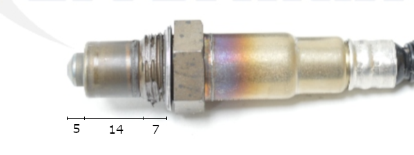
For number 4 - the PCV + AT uses the LSU 4.2 sensor (yes, 4.2), I'm not sure if this has been updated on newer units. They only sell one replacement regardless, so I'd assume they are all 4.2.
Dimensions of the LSU 4.2 tip in mm given on picture. The only part with holes for sampling is the conical part at the very tip. I can think of no reason that any part further back would need to go in the exhaust stream.
Number 5 - When it comes to me, I'm still just going to use the one sensor in the final merge. If I was a racer looking for every advantage, then I'd certainly tune by cylinder. YMMV.
-
1
-
-
If you are OK with the signals flashing really fast, then disregard this. If you want the normal signal flashing speed you will either have to add ballast resistors in parallel with the signal LED OR acquire a solid state flasher relay that doesn't rely on the resistance of an incandescent light for switching frequency.
Ballast resistors: https://www.amazon.com/4Pcs-Aaron-6ohm-Load-Resistors/dp/B00L4V9ECY/ref=pd_lpo_vtph_263_bs_t_1?_encoding=UTF8&psc=1&refRID=2WYD8NQ5HQQ0NAEFZD3A
Another possible issue by swapping from incandescent to LED is that your regulator-rectifier will have to dissipate more heat if it is of the shunt type (OEM, FH020AA) because this energy would normally be dissipated by the bulbs. If series (SH847) then this is not an issue. That said, this is a nearly trivial amount of energy, so it may not be an issue.
-
1
-
-
6 hours ago, sfdownhill said:
MadScientist, can you please expand on the 5th gen 'internal gear indicator', how to calibrate it, and how a PCV receives this data? I was under the impression that our beloved 5th gens have no means of keeping track of gear selection other than neutral. Love to learn otherwise.
The bike doesn't know what gear it is in, but the PCV has vehicle speed and RPM inputs. I calibrated the PCV by entering the speed:rpm ratios for each gear by, you guessed it, riding around with a laptop stuck in a tank bag. This would be trivial to do with a dyno, however.
You can purchase a display from powercommander that interfaces with the PCV and displays vehicle data, including the calculated gear position. I called it an 'internal gear indicator' because I can't actually see what gear it thinks I'm in, unless I have a laptop hooked up while riding.
-
As far as the PCV goes - I would say maybe. From the discussion here, there seems to be some kind of issue with the newer firmware and 5th gens. I have been running mine with no issues since 2010, I have also never updated the firmware. I run autotune all the time with a vacuum switch hooked up to turn the autotune off during overrun - I was getting really wonky trim values at low throttle openings until this was performed. I have tried running with autotune disabled and noticed no ill effects; of course this is just running the stored map built from the autotune data. If it is of consequence, I have calibrated the internal "gear indicator" and adjusted target AFRs for each gear, throttle position, and RPM. My O2 sensor is positioned in the 2nd merge collector (all 4 cyl) and I don't run any special offsets for the front vs. rear banks.
I've been strongly considering MyTuningBike for the ability to run O2 sensors in each bank, but what I have works fairly well and the cost of entry for MTB is steep.
-
1
-
-
With PC5 running autotune, bosch 3 bar FPR, large airbox/dual trumpet mod, and Micron slip on I average about 40 mpg with about 60% of mileage on interstates and 40% stop and go city.
I had poor economy several years ago that was resolved with replacement of the leaky stock fuel pressure regulator and injector cleaning. At the state of mods on your bike, I was averaging closer to 44 mpg.
-
2
-
-
I think if you try the Chinese levers, you may be pleasantly surprised. I was a little leery about it at first, but that was almost a decade ago now. I will say the fit and machining isn't always perfect, since I've installed a few sets on different bikes now and some have required a shim or a bushing to improve the up and down slop.
Hell, if you don't like them I bet you can unload them here for what you paid. That and a set costs about 1/3 of the price of one ASV lever. For that kind of savings, I'll do a little work to improve the fit. Oh, and try to avoid anything with red anodizing since it fades to a hideous pink color.
-
1
-
-
LOL, how is this possibly anonymous?!?
-
Hi Anonymous,
Thank you for your donation of 50.00 USD. We look forward to improving the forums with your donation.
Thanks VFRDiscussion
-
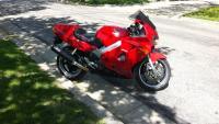
I'm assuming that you used fireblade triple trees, so a fireblade wheel with brake disks should fit right in. You may also want to find a fireblade front fender while you are at it.
-
Hi MadScientist,
Thank you for your donation of --. We look forward to improving the forums with your donation.
Thanks VFRDiscussion
-
Not necessarily motorbike related but depending on the size I've used battery terminal spreaders, external snap ring pliers, and chain pliers
-
Holy crap, that signature might be a little, um, excessive?
-
Wow you really have patience and/or a really dirty camera. I did this on the 5g and thought about making a guide, but I have trouble being bothered to stop and take pictures. Not to mention figuring out what things might be important to have pictures of. My guide would read something like:
Take everything the fook apart.
Throw out nearly everything made of rubber.
Order everything that is worn out.
Get busy with other projects and store it all for 6 months.
Put partially back together.
Discover parts are missing.
Order more parts.
Find missing parts.
Curse.
Reassemble.
-
1
-
-
FJ12 -
What brand do you have on the trailer? Sounds like they are external mount. Have you ever checked their accuracy?
-
Dae's Post in the Angel GT mileage thread shows a very cool TPMS that I want to have on my bikes.
Rather than necromance this thread from 2008 or this one from 2011, I thought I would start us off fresh.
So, who out there is, or was, running a TPMS on any of their bikes? How do you like it? Is it precise? I don't really care exactly how accurate it is, as long as the inaccuracy is predictable. If you are using an external type, how heavy are the transmitter caps and will they interfere with anything if mounted on a 90 degree valve stem.
I don't expect a whole lot of responses, but please don't recommend hand held tire pressure gauges. Since most of my bikes are driven daily, the prospect of getting the pressure gauge out, moving the bike so the stems are accessible, measuring, and washing the brake dust/road grime/chain lube off of my hands is unattractive. $100-200 for a TPMS would be worth it to me for the time spent and also provide a warning system for slower leaks while on long ride.
advrider alerted me to the existence of the FOBO bluetooth/smartphone TPMS. This is now a frontrunner, assuming it fits my 90 degree valve stems. Riders say the sensors weigh about 10g and they are 26mm diameter ~19mm tall. I've emailed FOBO for more info, but if anyone is using this, feel free to chime in.
Upon doing some calculations: (Rear Wheel)
The radius from wheel center to cap is ~190 mm
The rotational speed of the wheel is ~ 980 RPM at 70 mph
With a 10g weight, gives a centripetal force of about 20 N (~4.5 lbs-force).
This is ideal and neglects gravity (frictionless with horizontal axis). In reality, the centripetal force is cyclic and changes when Earth's gravity pulls with or against the centripetal force. I didn't measure the front wheel, but it looks like the radius will be larger, so the force greater.
All that crap aside, I think this may require re-balancing. Anyone out there re-balance? I did neglect the weight of the original valve cap, which makes this a bit worse. Even so, the cap/sensor now applies this as shear force to the end of the valve stem. I'm now thinking that 90 degree valve stems might be a poor choice for mounting the sensors.

What did you do to your VFR Today?
in Eighth Generation VFR's
Posted
Just out of curiosity, was the wire soldered (either tinned or to the connector)?