


toro1
-
Posts
470 -
Joined
-
Last visited
-
Days Won
2
Content Type
Forums
Profiles
Gallery
Blogs
Downloads
Events
Posts posted by toro1
-
-
Can I have a drumroll please?.........
TADA! <-- click here
It works folks, it works mighty well. The blower is extremely quiet, with just a slight whistle/whine while cruising around; it's actually quite complimentary sounding to the gear driven cams. I am completely blown away that the bike can run with the rudimentary fuel map I have loaded -- while riding, the air/fuel ratio dances all over the place from 11 to 15, but it idles great and runs strong.
Initial riding impressions: cruising below 5000 rpm (I have to keep the revs low until the blower breaks in) the bike feels just like stock, but keep it near that 4500 rpm mark, and even in 3rd gear, you can tell the bike just wants to start pulling. Like I said before, the blower is very quiet but you can hear it, especially on decel, and it sounds mighty fine. The exhaust is definitely a bit louder than I previously thought, but it sounds absolutely wicked (was that a MotoGP bike that just went by?) yet still streetable.
I have some serious tuning that needs to be done before the bike is good to go, but I've certainly crested the hill. The belt tracks straight and true, and I can't see it ever coming off. The intake and tubing clears the tank, I don't have any oil or coolant leaks, and my temp didn't get above 175 (granted, it was a short jaunt).
Here are some pics of the install and final assembly:

starting_shot.jpg
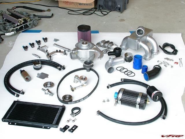
parts.jpg
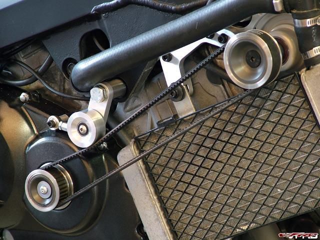
drive1.jpg
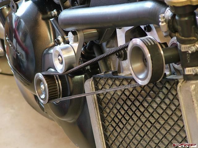
drive2.jpg
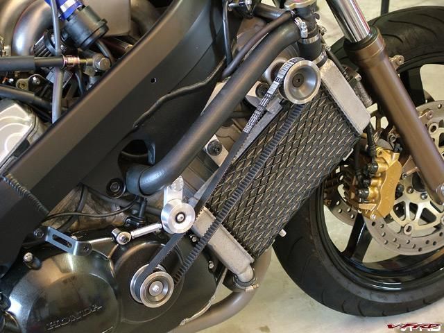
drive3.jpg
intake1.jpg
intake2.jpg
intake3.jpg

back_together_again.jpg
Once I get it running better, I'll come up with a real video to demonstrate the bike in all its supercharged glory. Until then, enjoy what I have posted here.
-
 1
1
-
-
Very impressive. I can fully appreciate how much work went into those 6oz caliper mounts. This merits a big time :thumbsup:!
-

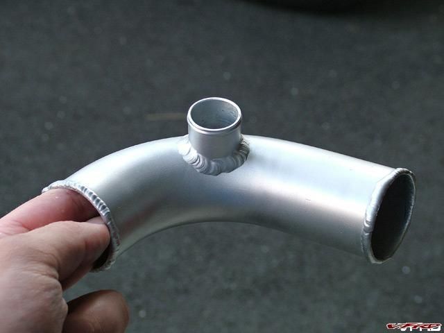
welded_intake.jpg
amazes me that there are no issues w/ clearance w/ the gas tank... can't wait to see the finished product!
Well, it looks big...until you compare it to that monster of a stock airbox:
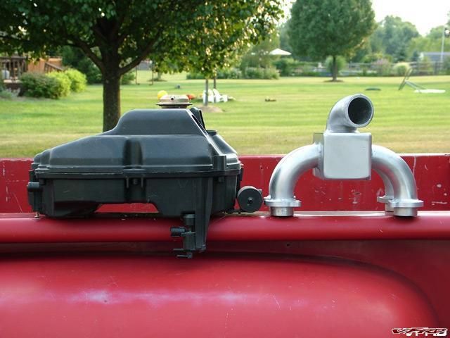
intake_comparo.jpg
As you can see, the new intake is no higher than the old one -- plus, it's sticking up an extra 1/2" in the air due to the runner tubes that sit down inside the throttle body. You can imagine how much room there would be if I was able to go with the side feed entrance.
Just goes to show, size is all relative

-
The last of the major fabrication is done. All that's left to do is make a few brackets here and there, and put her back together. Take a look see:

idler_assembly.jpg
welded_intake.jpg
intake_tube.jpg
-
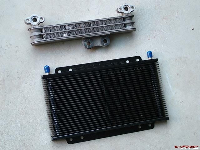
oil_cooler_comparo.jpg
Old cooler on top, new cooler on bottom. Pretty self explanatory, no?
BTW, the new cooler is about half the thickness of the old one.
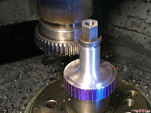
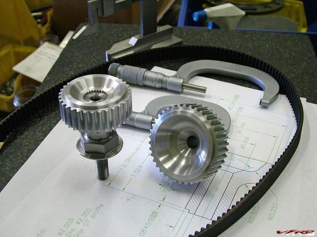
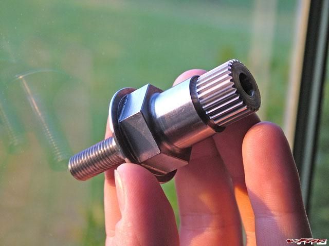
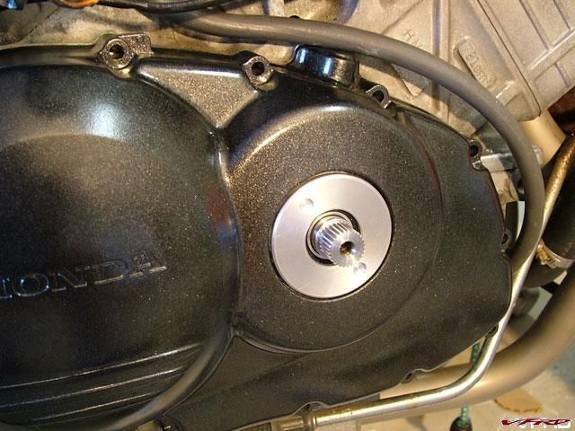
-
Someday, hopefully, I'll get around to doing the single-nut hub mod, so I can slap on a rear mag wheel to match the Marchesini mag front I have on there now. It's incredible how much turn-in and steering effort are improved by slapping on a lighter hoop, so if I can remove even more rotating weight from the rear (combined with suspension mods), this bike will be an absolute dream to ride.
PS -- the linked picture was taken moments after I got the bike together, so please refrain from the usual poultry-related comments... :D
-
And..... we've reached a new low :blink:
:lol:
Hey, people are just excited, right?
Anyway, I figured out the intake (yes Dan, I think your technique worked :thumbsup: ). First, let me show you the original plan:

intake_design_1.jpg
As nice as it would be to run the intake along the side, it just isn't happening. You can see here that while it looks like there's room, remember that the silicone 90 is sticking inside the plenum about an inch, so when you put it in its required location, the bend becomes less than ideal. Also, the T-piece, which I thought would simplify things, only made the setup more complicated and crowded. Thus, we look at design #2:

intake_design_2.jpg
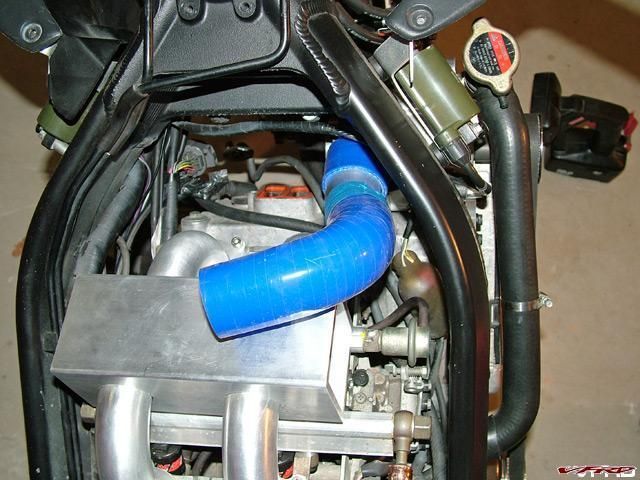
intake_design_2-2.jpg
It's oh-so-simple -- a silicone 45 will come off the blower (aluminum in picture) and attach to an aluminum 90 (silicone in picture), which then will meet up with a close-radius cast aluminum 90-degree elbow (not pictured) and go straight into the top of the plenum box. Equal air distribution and fewer parts are the results of this revised intake, as well as smooth bends & easy assembly.
The only downside is now I have to weld a nipple onto the aluminum section for the bov, but that's no biggie. Pictured below is where the oil canister and bov will go:
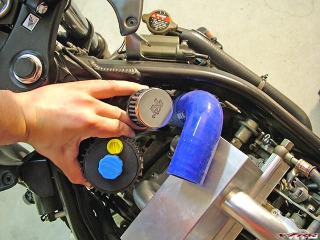
oil_canister&bov_location.jpg
Hey, it's ready to run! -- okay, maybe only in my mind, but it's starting to resemble a completed bike once again.
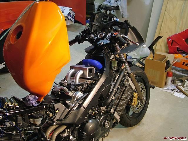
ready2run...not.jpg
-
First off, thank you so much for your kind words Dan -- I take your compliments to heart. To think that I just thought I was a kid souping up his bike...wow. I hope I don't let you down. :blink:
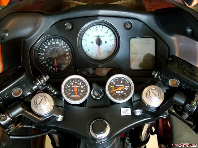
Finally, finally, finally, I got the gauges done. I thought I was going to go crazy on more than one occasion trying to keep everything straight...
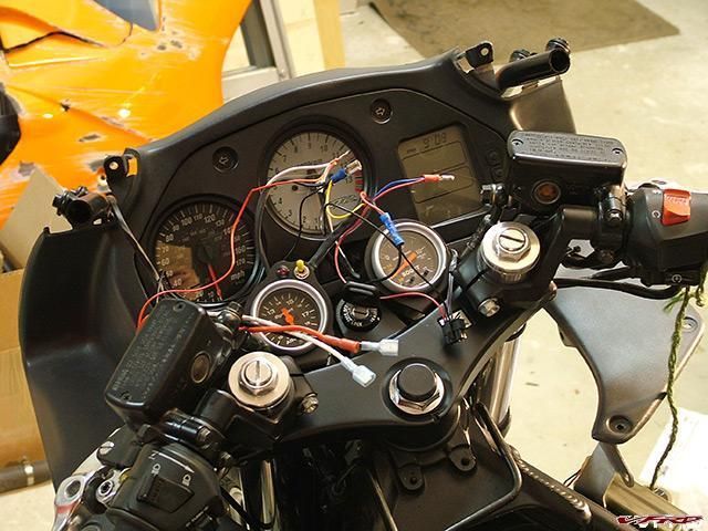
lots_o_wires.jpg
...but I got it figured out.
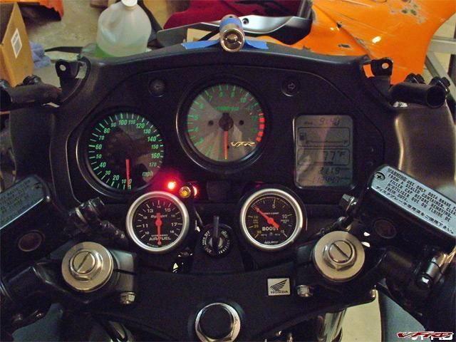
gauges_done.jpg
To record data with the Wideband Commander, you simply flip the toggle switch down; the LED I wired in comes on to let you know when you're recording and when you're not. The housing taped to the top is the knock light/shift light -- it will be permanent once I get the bodywork back from paint.
It was too dark to get any good pictures of this setup, but I have to admit, it looks trick in person. What you can't see are the gauge cups that match & blend in with the rest of the bike -- I wanted just the faces to draw attention, and that's what I ended up with.
Here's a final shot in the dark with the gauges lit and the knock light showing red:
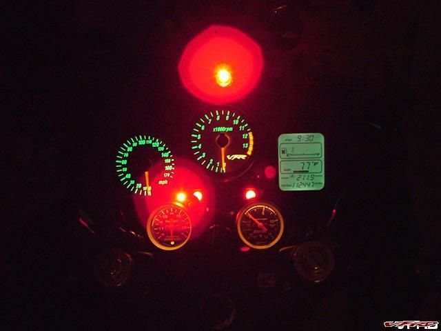
gauges_all_lit_up.jpg
-
The past week has been frustrating. Parts I need still haven't come in, and everything I do seems to take longer than expected. Oh well, I've just got to keep plugging along. Here's what's new:
I figured out where the gauges needed to go, grabbed some sheet aluminum, layed out a design, and cut away:
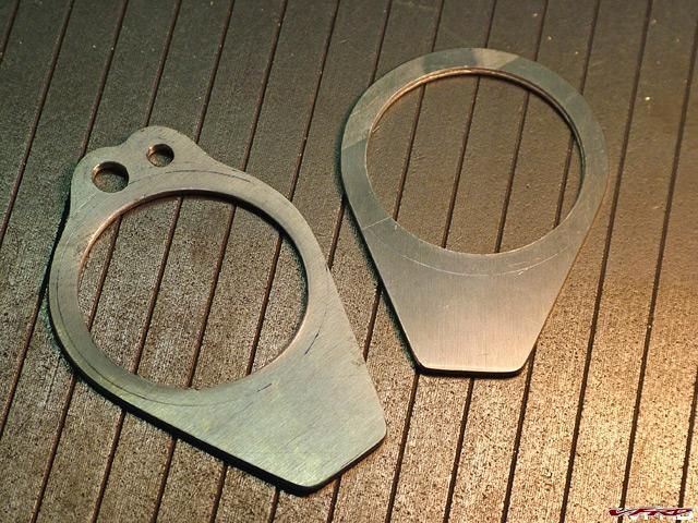
gauge_brackets_just_cut.jpg
Brought them back to the house, drilled the top tree, painted everything, and bolted them up:
gauge_brackets_mounted.jpg
I so badly wanted to have a shot with everything in place, all lit up, but the wiring is insane and I couldn't get it done tonight. I have so many wires going to so many places, it's really hard to keep track of everything -- it's like a jigsaw puzzle figuring out what has to go where and how it all fits together cleanly & properly. A few more hours tomorrow and I should have it done. Wondering what those little holes in the left bracket are for yet?
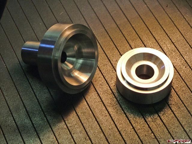
Now for everybody that was wondering how it was going to be done...
finished_pulley.jpg
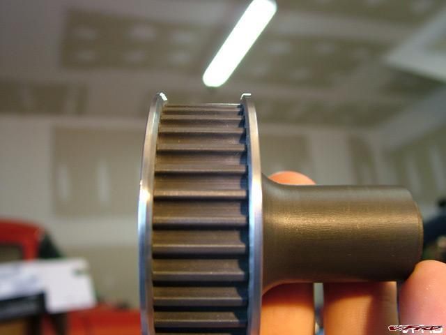
flanges_inside_view.jpg
I had to get the pulleys hard anodized first. Machining the stainless flanges came next, and they were then heated significantly & dropped on the pulleys. I allowed them to slowly cool back to room temp and shrink onto the pulley, into the machined groove -- they are going nowhere fast. The 20º inside angle is per Gates and should allow smooth tracking even if the pulleys are out of alignment slightly.
Finally, I'll post up some pics of the completed exhaust and O2 sensor.
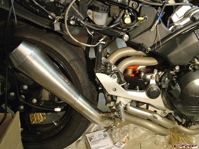
O2_hidden_wires.jpg
Hey, where are the wires? There's actually a huge connector hidden behind the foot guard and I was able to thread the rest of the wire through an existing hole in the engine block.

exhaust_shot.jpg
You have no idea how badly I want to hear this thing roar. It's so close, yet so far away. I still need the radiator bracket machined, I need to make the idler, the intake and upper bracket need to be welded, the intake connector tubing needs to be completed, I've got to remount the coils, yadda yadda yadda, hopefully it won't be too much longer... :blink:
-
Fuel economy will suffer...But who cares! :thumbsup:
Thank you Rob!
Here's the upper bracket, just off the machine. This part bolts where the oil cooler bracket used to reside & will very rigidly tie-in and locate the top of the supercharger bracket.
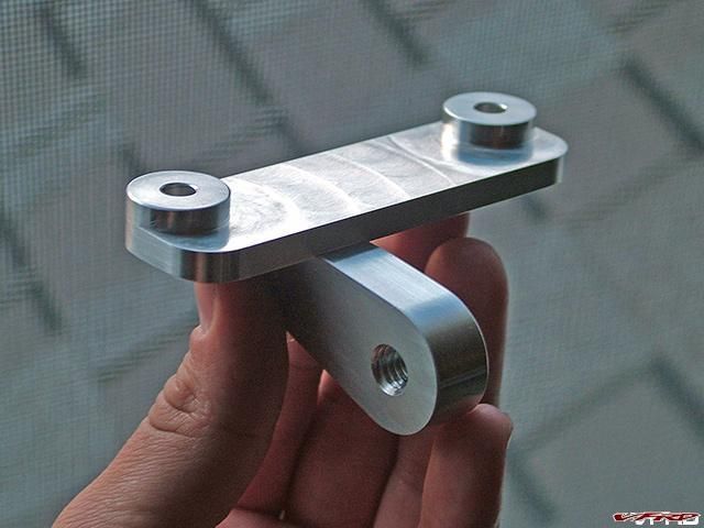
upper_bracket.jpg
It's actually two parts - I need to get the lower section welded to the top section, but otherwise, it's ready to go.
-
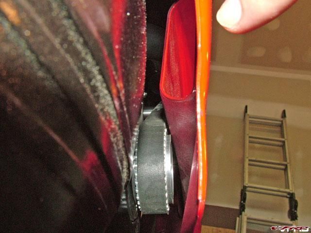
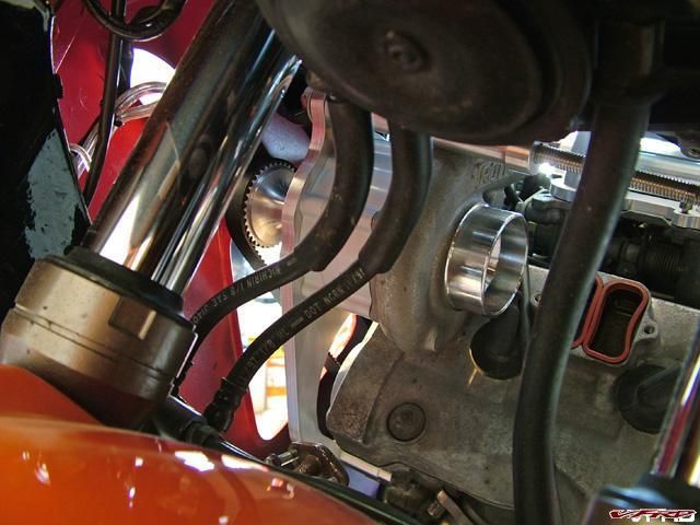
Just to clarify an earlier statement I made, check out this picture:

belt_rad_clearance.jpg
Pay no attention to that bolt sticking out the end -- it's only temporary. Anyway, you can clearly see there's a good 3/4" of space between the radiator and the belt, and the radiator is even spaced out from the engine a bit, so there should be no clearance issues.
-
Those pulleys look great. Next big thing I'm waiting for is to see the drive belt running from the crankcase cover to the blower... and how you're going to work the plastics around it.
Your wish is my command...
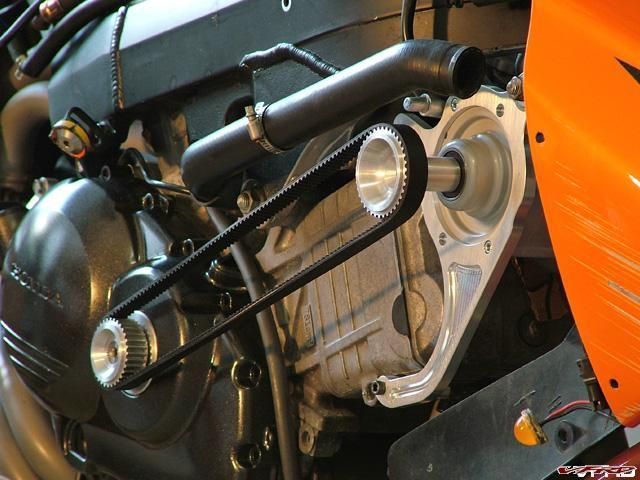
pulleys_mocked_up.jpg
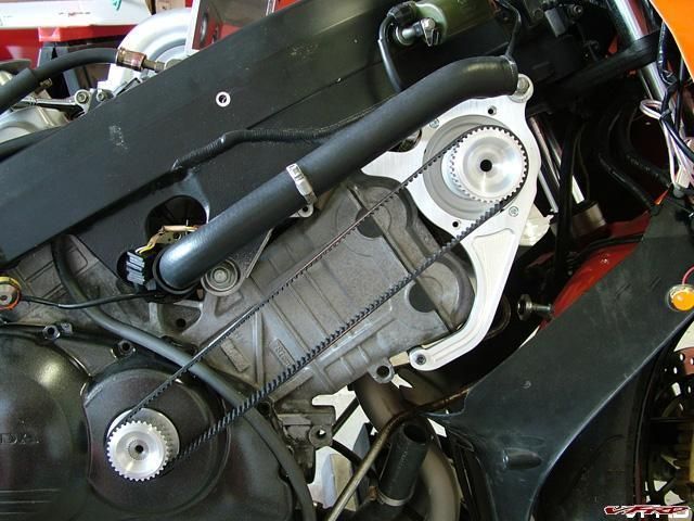
pulleys_mocked_up2.jpg
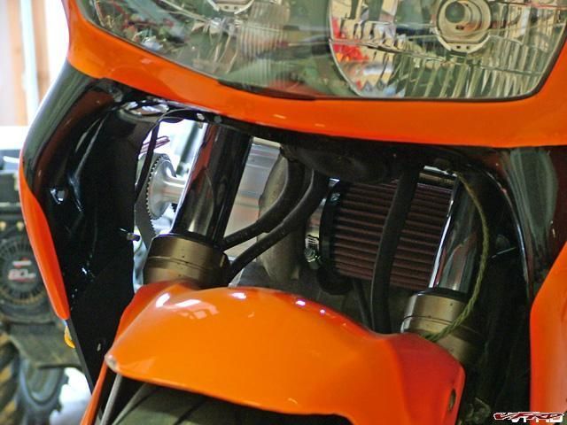
Now for the fairing pics:
inside_bodywork.jpg
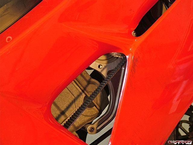
peeking_through_side.jpg
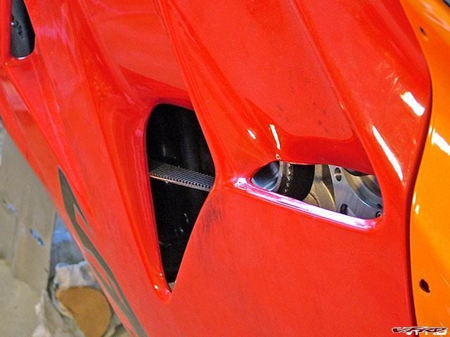
peeking_through_side2.jpg
As you can see, there's not a whole lot of room for the belt or pulleys, but most of it can be fixed by spacing out the fairing & massaging certain parts. It's hard to tell from the pictures, but the belt and pulleys are right up against the plastic. Some sections will have to go under the knife (aka dremel).
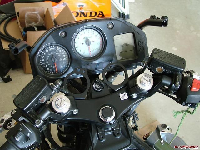
new_gauge_mockup.jpg
I just wanted to figure out where I want the gauges. I'm liking this position from both an aesthetic & turning clearance point of view.
lookin_through_front.jpg
lookin_through_front2.jpg
The view from up front. Plenty of cold air coming through there, plus the radiator hoses clear both the filter and the blower. I'll mount the oil cooler just below the blower, though I'm still not sure whether to reuse the old one or get a new one.
-
So how do you extend a VFR swingarm?? :goofy:
You could throw a Honda Civic wheel on there with a slick tire though, and see what it'll do at the strip... :rolleyes:
Hey Seb, you mean like this?
:salesman:
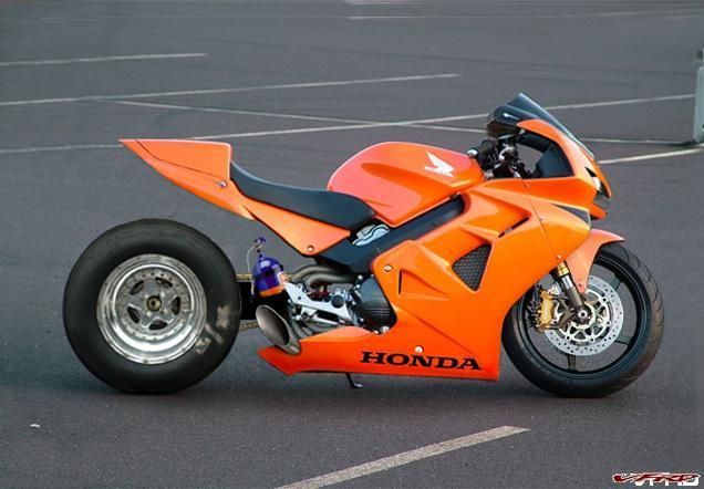
Drag_vfr.jpg
-
Yes folks, the pulleys are done! Things should start moving faster now...
Here they are as blanks:
pulley_blanks.jpg
They then were popped into the shaper and both the internal & external splines were cut:
pulley_shaper_cut.jpg
The completed parts.
pulleys_cut.jpg
I should be able to finalize the bracketry now and get the radiator fitted. Plus, I'll be able to figure out exactly where the bodywork needs to be trimmed/clearanced/heated & bent into shape to fit the drive assembly behind the plastic. As for the pulleys themselves, once I'm done with the test-fitting, they will be sent down to get hard anodized and the flanges will be installed.
-
Well, the next step in this project is to get the brackets finalized, but I can't do that until I know the final position of the supercharger, which I won't know until I get the pulleys mounted, and since I don't have the pulleys, I'm at a standstill. I've also found out that the silicone pieces I need for the intake won't be in for 2 weeks, so there goes any shot at my June 1st deadline.
Anyhoo, I've started to wire in the Wideband Commander, I'm finishing the exhaust, and today, I got the crank connector all finished up:
crank_connector.jpg
It mounts right into the end of the crank and right on top of the pulse generator disc.

connector_mounted.jpg
Here you can see it sticking out of the clutch cover & modified timing cover. It fits perfectly.
connector&case.jpg
The driver pulley will be splined to fit onto the connector & will be held on by a bolt in the end.
-
This is starting to get fun. After all the measurements and mockup brackets, I finally have a real supercharger bracket, and get this -- it puts the blower right where I wanted it! It's almost like I engineered it that way!
Joking aside, here's a pic:
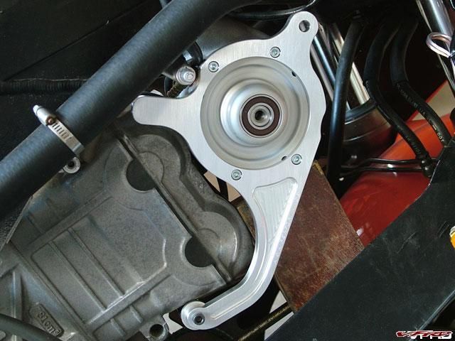
rotrex_bracket.jpg
I had it made out of 3/8" thick 7075, so it's plenty strong & still lightweight. I just need to make standoffs, the upper bracket, and the left connector bracket and the whole assembly can be mounted up for good.
-
After all this talk of epoxy and welding, I have made a decision that if I ever have to make another manifold, it definitely will have silicone bends with separate adapters. I already know exactly how I want to do it; more expensive - yes, more parts - yes, not as nice looking - yes, much much easier to build - YES. It took me hours to hand work those bends back into round & to cut them the exact length and perfectly square.
I also am pretty certain that I will weld the whole assembly together. There's one more place I want to call about the epoxy, but I have found a very capable welder that can do the job for me. Either way, this is the last all aluminum intake manifold I'll make.
Having said all this, here's what I got accomplished this weekend. First, I needed to cut the plenum material and mill holes where the runners will attach.

mill.jpg
I then used a flycutter to finish bore the holes and counterbore them 0.050" to allow the tubes to locate in the plenum.
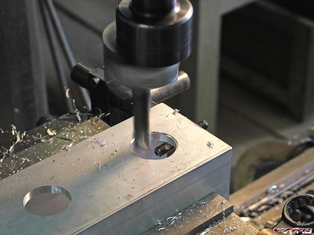
flycut.jpg
The reason I went with 1/4" wall square tube is so that I could add a full size radius on the inside of the plenum without having to make a separate component. To add the radiused entry, I ground a radius into a piece of tool steel, mounted it into the flycutter, and then cut from the underside until the radius was generated:
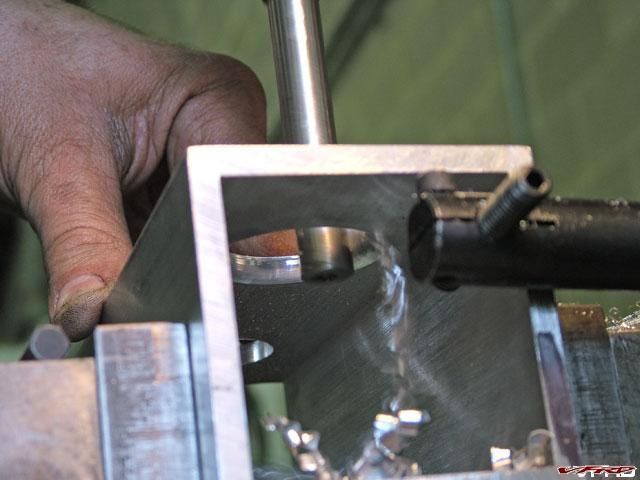
flycut-radius.jpg
It worked out great -- here are some pics of the semi-completed intake.
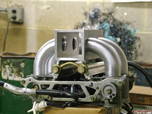
intake_view.jpg
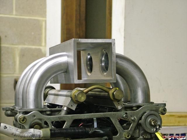
intake_view2.jpg
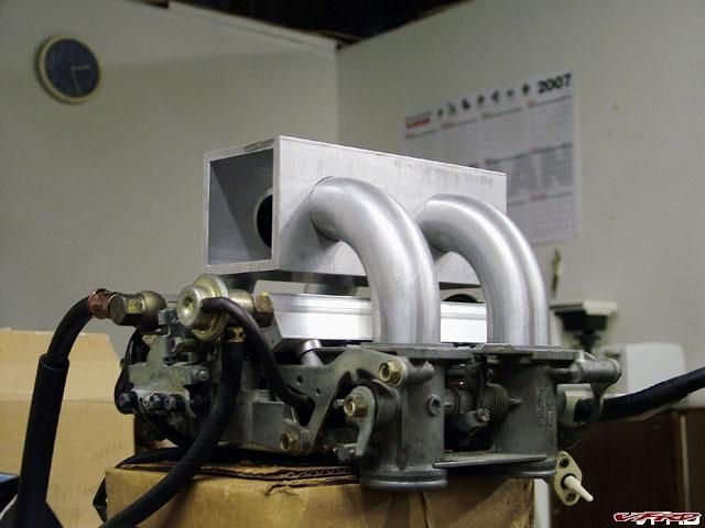
intake_view3.jpg
I still have to make the endcaps, drill it for the temp sensor, and radius the edges, but it's getting close.
-
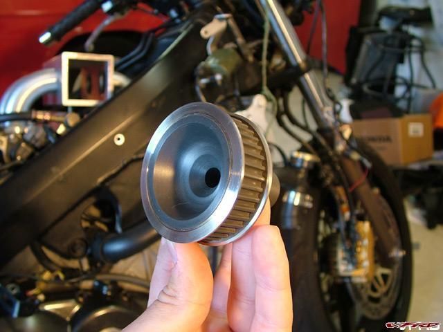
Believe it or not, this used to be the timing cover:
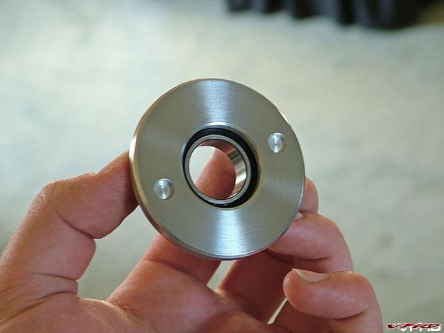
timing_cover_front.jpg
This mod required some thought to accomplish, but it turned out great. The bearing needed to be prefectly centered in the cover in order to avoid improper loading of the crankshaft, and believe me, it's perfectly centered.
The two small holes are for a spanner wrench that will tighten the cover back down (since the original hex is now long gone).
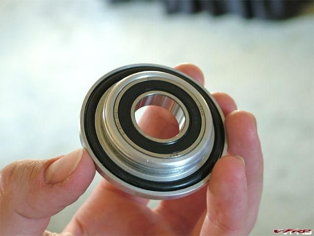
timing_cover_back.jpg
It's a slight press fit into the cover, and the double seal assures that no oil can escape from the crankcase.
-
Hot off the CNC -- parts baby!
I said earlier that I had a slick way to mount the new intake to the throttle body, and here it is:
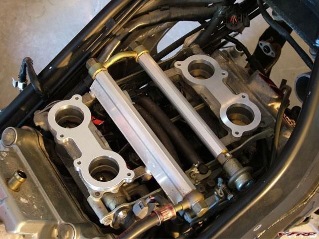
throttle_body_plates.jpg
The intake runner tubes will be a tight slip fit through the holes of the throttle body mounting plates & will bottom against a small lip in the throttle body. These plates are held down the same way the stock airbox is, with (2) M5 bolts around each runner. How does it seal, you ask?
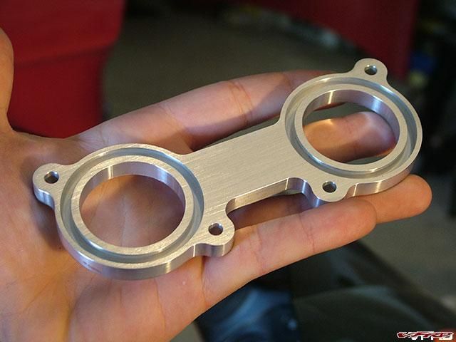
o-ring_groove.jpg
Machined into the base are grooves for properly sized Viton o-rings, so no rubber/silicone connectors & hose clamps are needed to hold the plenum to the throttle body, just the 8 socket head cap screws.
I'm still undecided whether I should weld the tubes in or use special aluminum epoxy. I'm afraid that if I weld it, the base will distort slightly and compromise the seal, so I'm really investigating the epoxy. After all, Lotus epoxies their entire cars together (welding aluminum can reduce strength around the weld by up to 50%), and with thin wall tubing, it might just be the ticket.
I also got the PAIR blockoff plates. I designed them to accept flathead cap screws since I need every thousandth near the intake of the blower. Nothing fancy, but they'll get the job done.

PAIR_cover.jpg
-
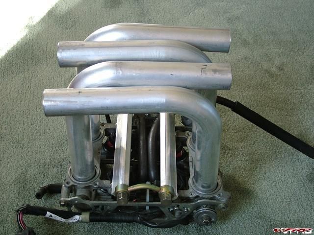
I thought I'd start mocking up the intake today, and the quickest way to do that is with a nice piece of cardboard:
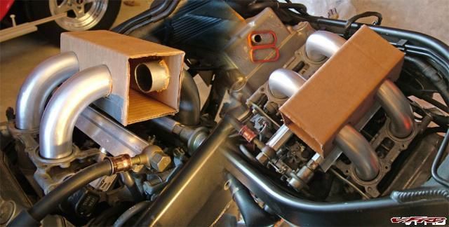
dual_view_o_intake.jpg
I cut the pipes down the shop and made sure that the ends sticking in the throttle body are all square & of equal length (I left the other end longer for the time being). I know what size plenum I want to run and have actually made a detailed drawing, but detailed drawings don't mean squat without seeing the part in real life. So, I cut a piece of cardboard into close-enough dimensions for mockup, and I'm proud to report that clearance wise, it's all good.
What I'm pondering now is whether to have a top entrance to the plenum or a side feed entrance. There is actually more room on the side with the blower (due to the engine being offset with the cam drive), about 3 inches worth from the end of the plenum to the inside of the frame. You can see what I mean below:
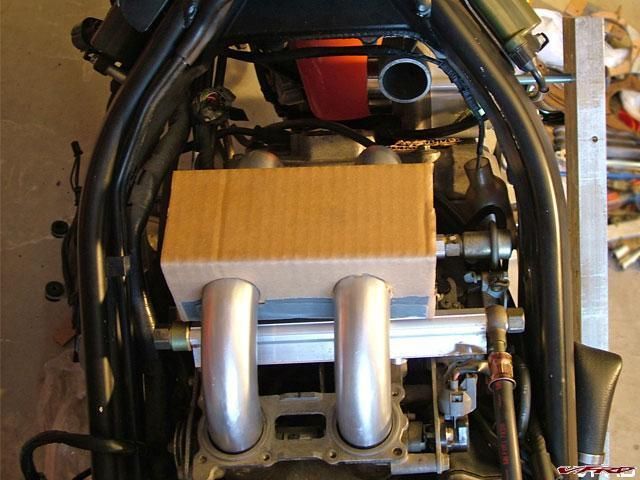
intake_overhead.jpg
What's bugging me now is the best way to go about plumbing the rotrex to the intake, and where to put the BOV. It's gonna be a tight turn into the intake from the top or the side, and will require a few 45º angles to make it work. I had planned on using a nice silicone T hose to mount the BOV, but I don't think there's room for that anymore. I'll figure it out later...
-
While I'm waiting for some parts to be completed, I thought I'd share a little bit of progress. Since I have the clutch cover pulled off, I decided to upgrade the stock springs to Barnett units. The plates are in excellent condition, and from what I've read, the hot ticket clutch setup is the factory plates with these springs, so hopefully it'll stand up to the extra power. The Barnetts are longer and a little stiffer than the stockers, and once installed, the clutch lever has a nice firm feel to it (not far from stock, actually).
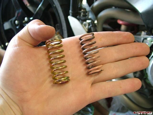
barnett_vs_stock.jpg
I also got the pump in. It's a Walbro unit with the same connector style and inlet & outlet location as the Denso unit. Hard to tell from the picture below, but the body diameter is ever-so-slightly larger than stock.
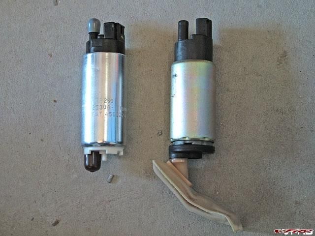
pump_comparo.jpg
This was the easiest mod so far -- truly a plug and play deal. The only finagling required was due to the aforementioned pump body being larger than stock. I simply took a set of needlenose pliers, squeezed the clamp together (which contoured the metal band around the pump) and put the screw in. Done. I already powered it up and it sounds great -- I can't wait 'till it's pumping massive amounts of fuel to those hungry cylinders :thumbsup:
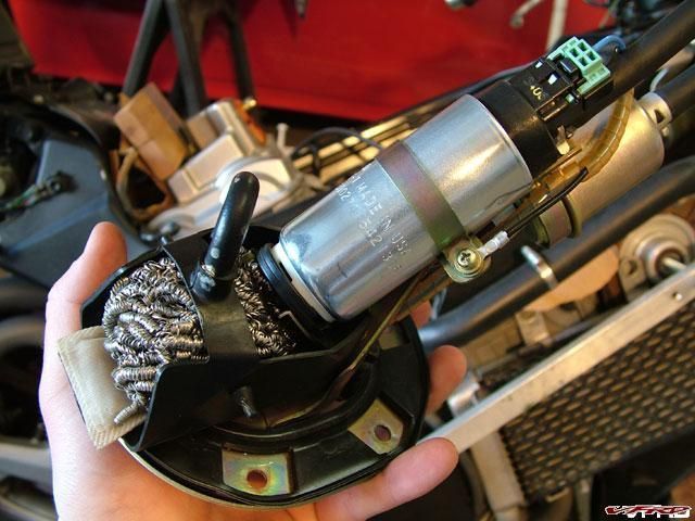
completed_pump.jpg
Can't even tell it's not stock!
-
I've been quite busy this past week making drawings of all the different parts I need to get machined. So far, I've designed & drawn up 6 separate components (with the help of good 'ole AutoCAD) and still need to design & draw up at least that many more, and let me tell you, with no easy access to a CMM machine, some of these parts are -t e d i o u s- to figure out. My goal of not chopping/modifying the existing hardware/frame/components has made this project tricky indeed, and my self-imposed deadline of June 1st is fast approaching. But hey, I wanted a challenge :D
I can give you guys some more pictures of freshly arrived items. First up is my non-bling, super low cost blow-off valve. It's a Bosch unit I picked up on ebay for a princely sum of $25. Originally off a Porsche Turbo, it should be more than up to the task of venting excess pressure on my low-boost VFR. I could have gone with a billet adjustable unit, but from what I've read, this valve has lightning fast response, and since I don't care about being able to hold 25+psi, I might as well save $150. I've also got an old K&N breather filter that fits perfectly on the outlet, and should quiet down the 'pssssht' slightly.
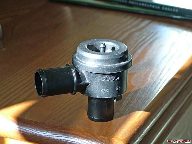
BOV.jpg
Also, I can give you a sneak peak at the intake I'll be making.
I bought some mandrel bent aluminum tubes which will form the the runner legs and directly connect the throttle body with the plenum.
mock_intake.jpg
No, I'm not building a tunnel ram, I just have the tubes sitting in the throttle body for some pre-visualization. Try to imagine the legs much shorter coming out of the throttle body, making a 90, then entering into a central plenum which is fed directly by the supercharger. Wait till you see how I mount the intake to the throttle body -- it's gonna be pretty slick. I'll get cracking on this once I get the brackets machined and I can mount the blower.
Alright, now I literally have to go back to the drawing board...
-
I got the pigtails, and of course, they aren't exactly plug and play. The female end fits the RCs perfectly, but the male end is slightly different than the stock Honda injector plug. After some research, I've only managed to find one place that sells the exact pigtails that I need, but they cost 4x the amount I paid!
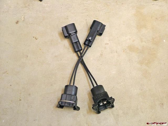
pigtails.jpg
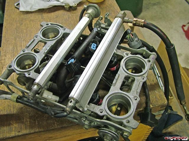
So, I found that by trimming some of the plastic off the plug end, they can be directly connected to the original wiring harness. I did that on all 4 pigtails, plugged them in, ziptied them up, and now the throttle body is complete.
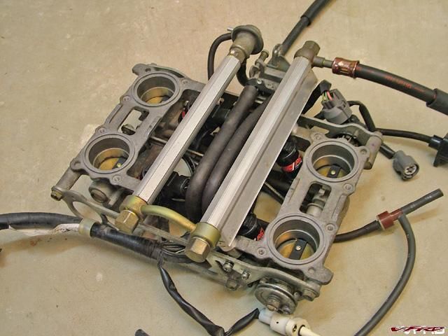
complete_throttle_body.jpg
-
When I found out the injectors I bought weren't exactly drop-in replacements for the VFR units, I was faced with 2 choices: 1) modify the throttle body to accept the RCs, or 2) modify the RCs to accept the throttle body.
Here's what I chose to do:
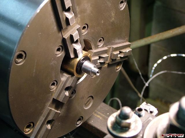
chucked_up.jpg
To make these injectors fit the throttle body required taking some material off the body and snout of each injector. So, I made a split collar that fit the injectors perfectly, then chucked them up in the lathe and took the ODs down to the right size.
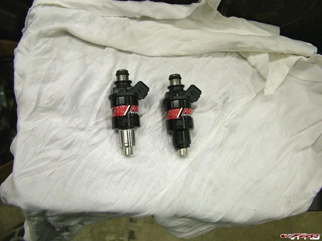
mod_vs_original.jpg
You can see in the above shot a before & after. Don't worry, there's still plenty of material left on there for the injectors to function normally.
I wasn't done yet. The RC injectors are actually longer than the stockers too, so spacers needed to be made for both the injectors and the fuel rail.
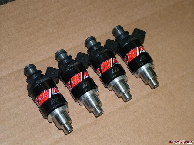
modded_injectors.jpg
injectors_mounted.jpg
In case you are wondering, raising the fuel rails altered the center distance of the stock connector between the two rails, so to fix that, I found a round piece of steel with the proper radius, placed the connector on top of that, and inserted both items into the press. Very carefully, the connector was worked to fit the new center distance.
Hopefully the pigtail adapters will be here shortly so I can button up the throttle body once and for all. And of course, more updates to come...
It Is Now Time For Some Serious Modifications...
in Modifications
Posted
Alright dudes, thought I'd give you some more ride reports. I had it out last night for the first time on public roads, and even with a less-than-optimized fuel map, it really runs sweet. For the first time, I really nailed the throttle (again, keeping it under 6000rpm), and to be honest, I was kinda disappointed with the power -- until I realized that I was in 4th gear and it was pulling like it used to from lower rpms in 2nd!
If just cruising around, the manifold pressure is in a constant state of vacuum, but as soon as you open up the throttle, the boost instantly jumps up -- I was seeing 2.5psi at ~5500rpm, which essentially is like a 12hp/12ft-lb gain at the wheel. The power delivery is electric smooth -- think of a subway taking off, that's what it feels like. The sound is absolutely intoxicating; between the new exhaust, the gear-driven cams, and the incredible whirl of supercharger under boost (which is far more pronounced than when cruising), I don't think there's a better sounding bike on the planet.
I recorded some good data with the wideband, so I'll be working on a new map today, but I can't wait to head out and feel the new power in 2nd or 1st gear. So far, everyhing is a-ok, though I think the oil cooler does indeed work too well. For the whole ride, I never saw temps rise above 175. When I take it out again, I'll keep an eye on that, but I can easily forsee adding an oil thermostat.
Okay, time for some glamour shots. Right now, I have the headlight, tailight, mirrors and turnsignals rigged up so that the bike is legal, but they are absent from the pictures here. Enjoy.
front_quarter.jpg
side_shot.jpg
rear_quarter.jpg
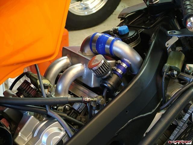
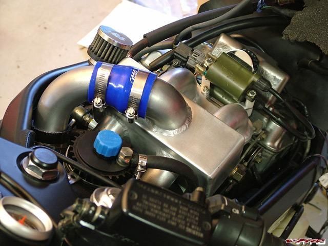
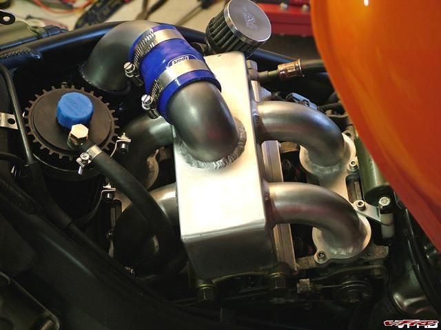
Some of you were interested in where the new cooler sits. Here ya go:
cooler_shot.jpg
blower_setup.jpg
rear_shot.jpg
Yeah, it's a fake novelty plate. Pretty subtle, huh? And yes, the opening of the pipe really is that big.