


toro1
-
Posts
470 -
Joined
-
Last visited
-
Days Won
2
Content Type
Forums
Profiles
Gallery
Blogs
Downloads
Events
Posts posted by toro1
-
-
btw I just noticed the modded lowers, what did you do?
I did indeed mold in the lower fairing panels from a 1st-gen 600RR. The only change I've made to them since I first completed the bike was to add the cutout for the one header pipe.
I also like that the front calipers are directly behind the axle - MotoGP style (but I am somewhat biased in that opinion).
I wonder why Ralph...

Everything went together fantastically, btw. The mark of a true craftsman.
-
Thanks for the compliments, guys. I'm really happy with the way it turned out.
Of course, it'll never truly be done, as there's always something else I want to do to it, but for now anyway, I think I'll just let it be and ride the beast once the weather decides to cooperate.
-
Really nice bikes you've got there, zroyz. I plan on starting up a new thread any day now to cover the build-up of the 6th-gen kit. It's coming. It's definitely coming.
:comp13:
-
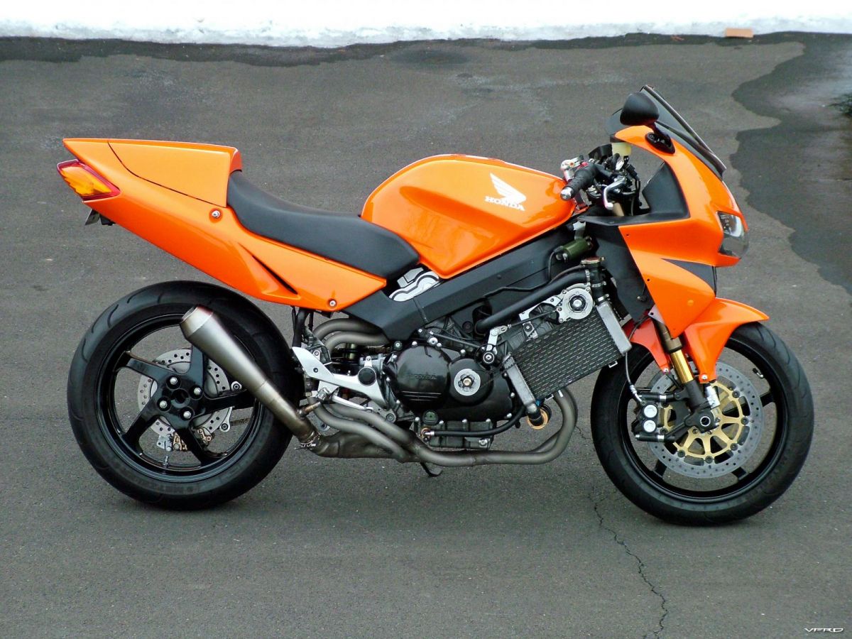
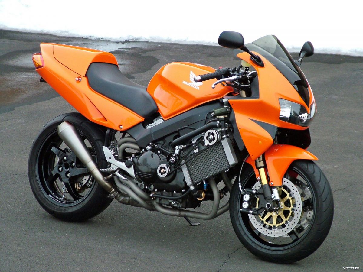
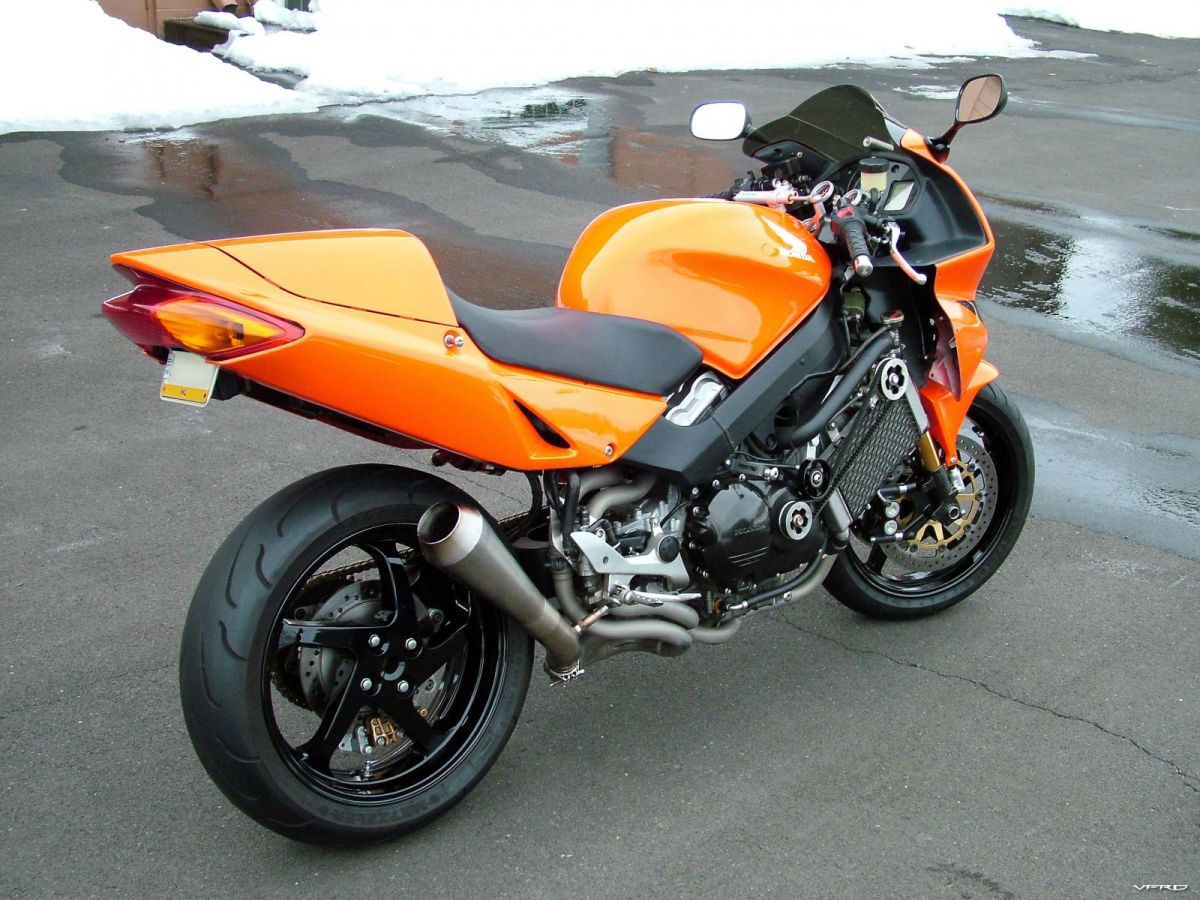
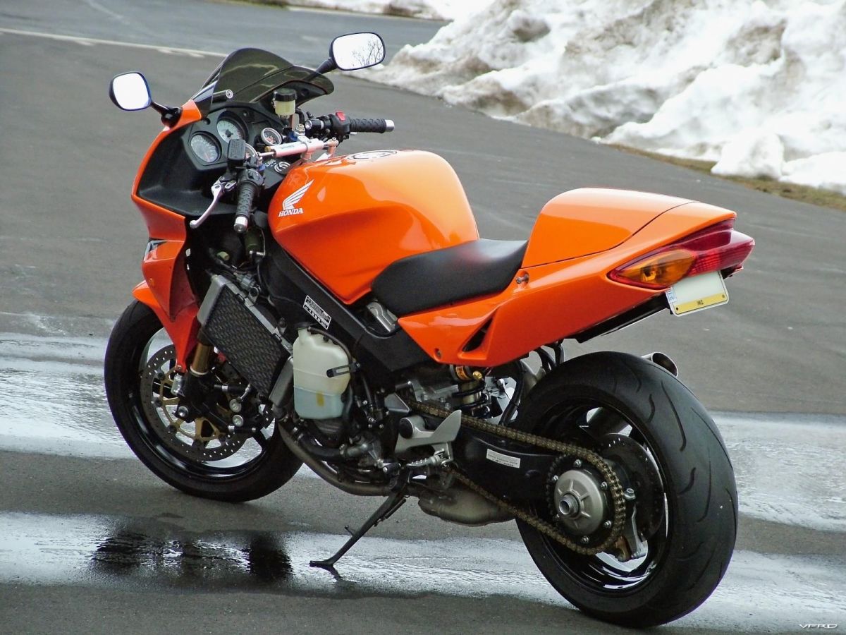
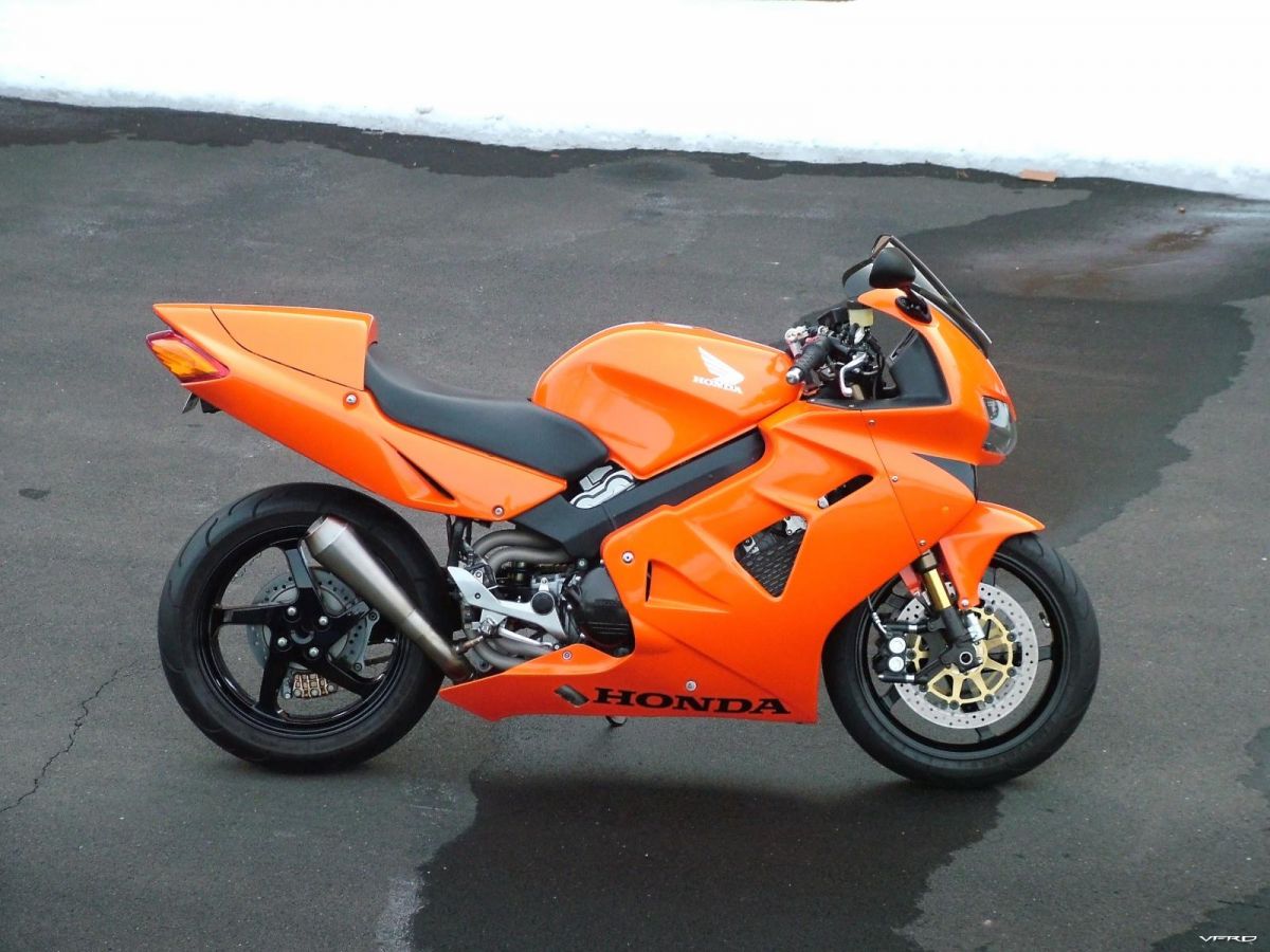
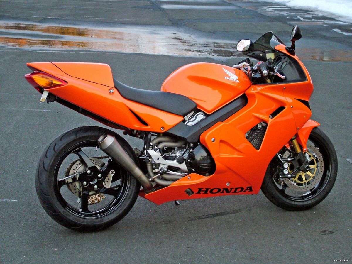
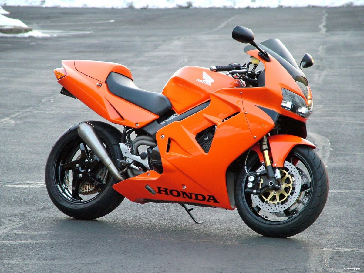
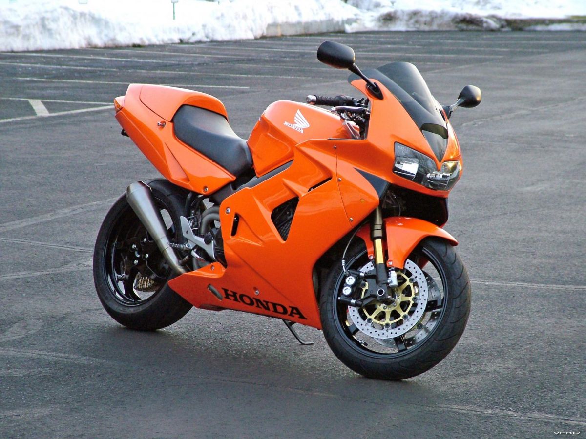
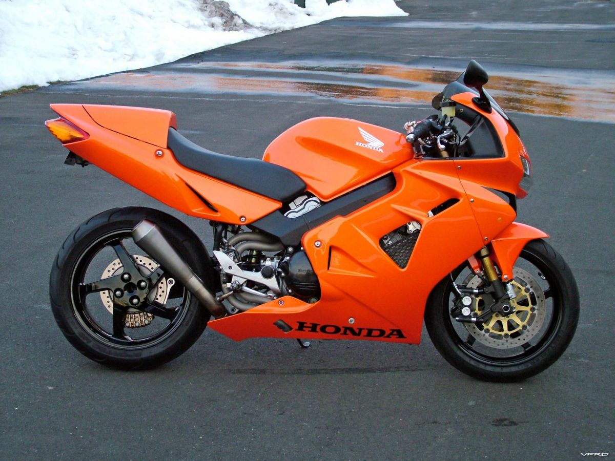
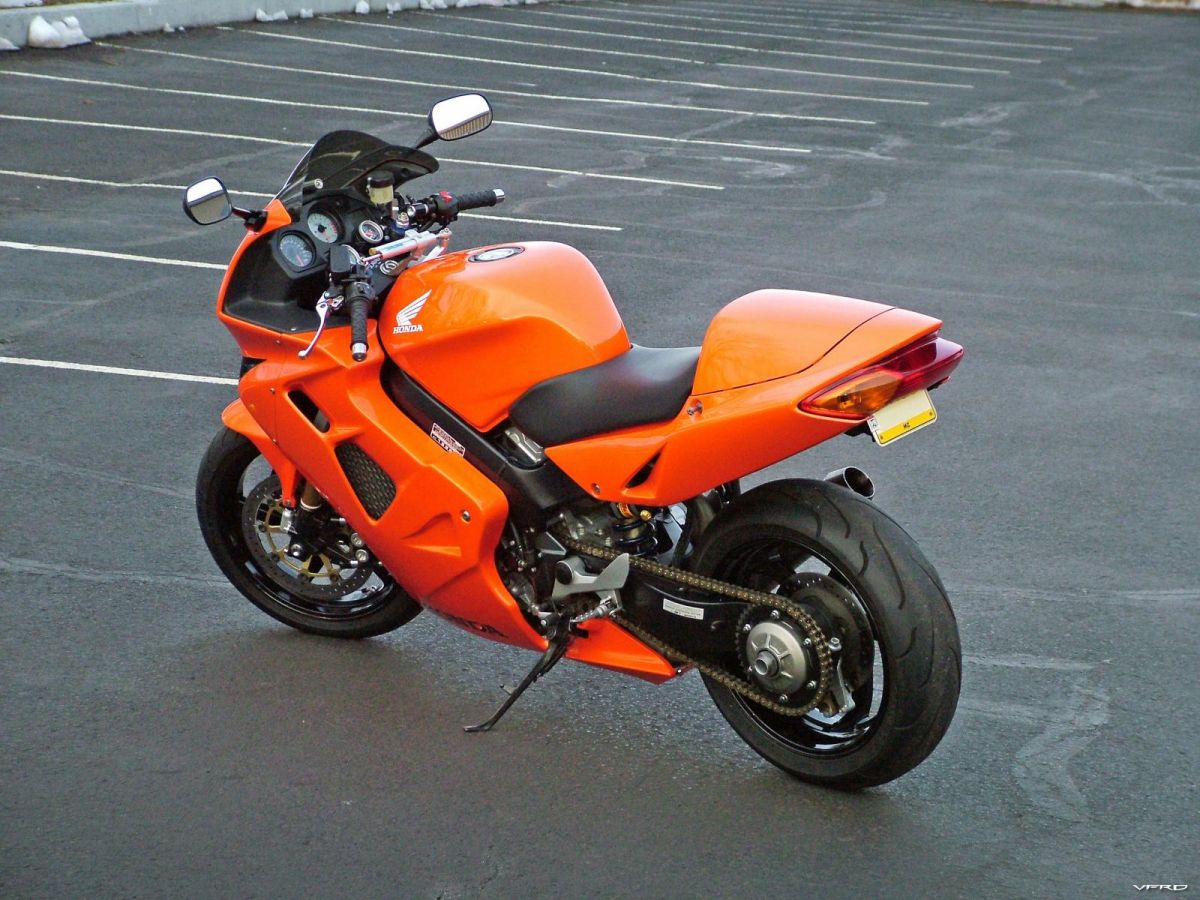
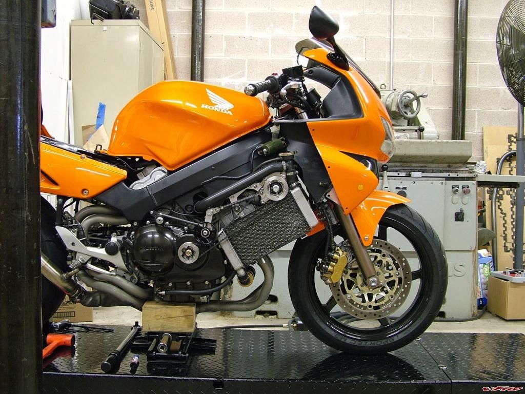
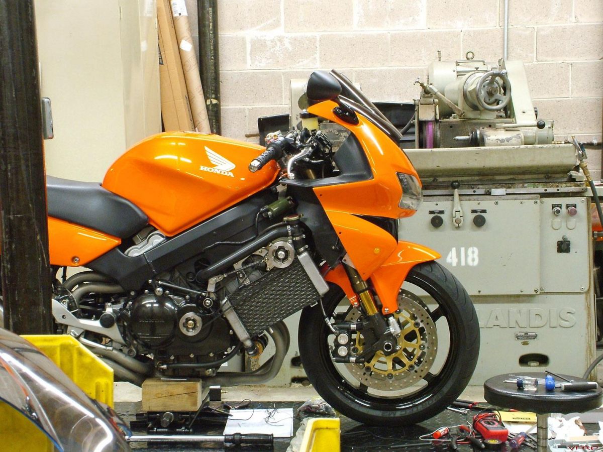
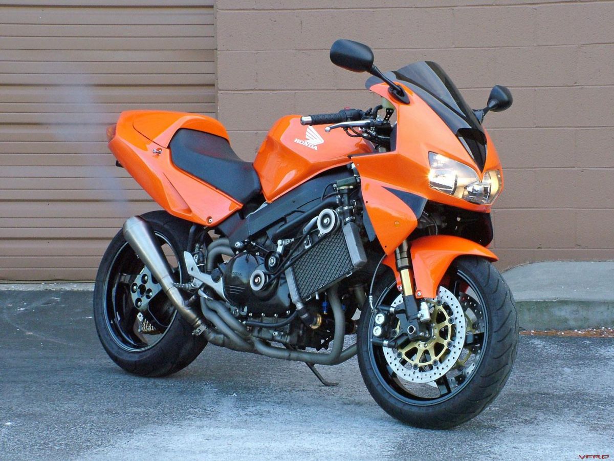
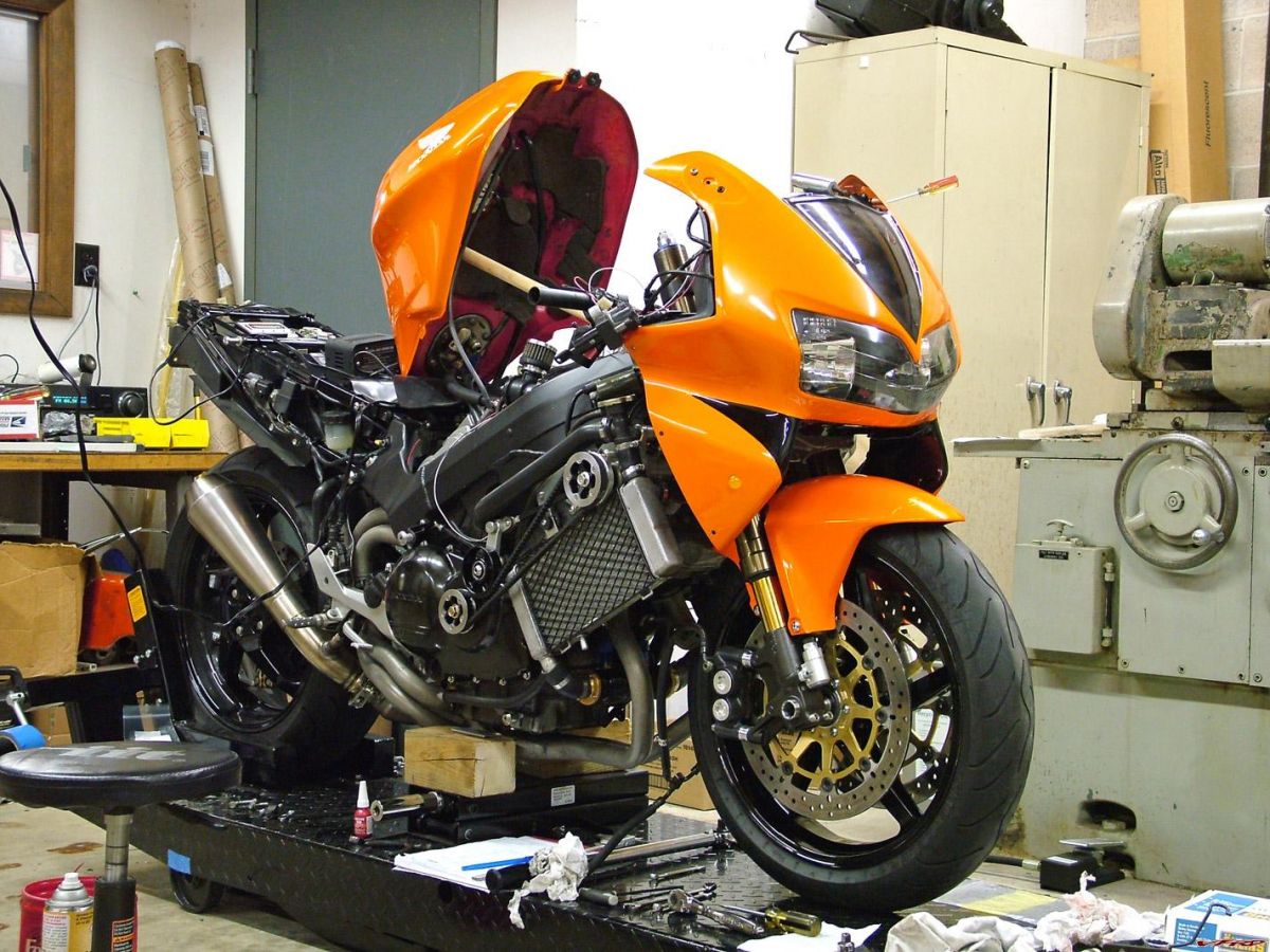
It finally stopped snowing for a few days, so I threw on the bodywork and snapped some pics of the completed VFR.
Here we go:
-
The Bioblade had it's heads mildly ported, I can't remember if they reground the cams, and it showed 125HP on the dyno.

That was also on an engine dyno, so ~110hp @ the wheel.
There's a lot of power left in these engines. Even without messing with the displacement, a set of high compression pistons, a nice high-velocity port job, a full exhaust, and a set of custom ground cams should net you every bit of 125-130hp @ the wheel if done correctly. The rest of the internals would handle the newly found power easily.
The toughest part is the trial and error process in determining the right combination to get it to run on pump gas & still produce the power you want. A GSX-R750 has no trouble hitting those numbers with less displacement (and very similar revs), so it can certainly be done, but it won't be cheap. Or easy. If some day I ever get the urge to build an all-out VFR, you better believe I'll be doing these mods.
I do concur, though, that a Torocharger would be an easier route to monster power... :goofy:
-
I didn't notice any change in performance, but what I do like is that I won't have to change them (iridiums) again for a long time. What PIA that job is.
Amen. I thought it was bad on the 90...98 was PIA+:fing02:
VFRs are an absolute cakewalk compared to a ZX-10R. On that bike, you have to remove both seats, 2/3s of the tail cowling, both side fairings, the inner fairing panels, the entire airbox assembly & ram air tubes, the PAIR system, the coolant overflow tank, and actual portions of the frame (not to mention moving the tank and radiator) just to gain access to them. On a 5th-gen you need to lift the tank and unbolt the oil cooler -- consider us very lucky.
BTW, I use NGK Iridiums in all of my supercharged applications; they're great plugs.
-
 1
1
-
-
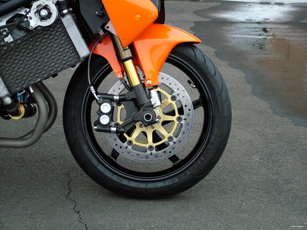
Hey good stuff. The steering damper probably isn't necessary, since the increased trail due to the RC51 triples actually makes the bike MORE stable.
In all likelihood, you'll run the steering damper fully backed off methinks.
But it sure looks blingy.
Did you come up with a solution for the lack of threads on the top nut?
True, but I also dropped the front end 1.5", and besides, I love the effect of dampened steering -- it ties the whole bike together every time you turn the bars. Undampened, the act of turning is super quick and feels disconnected from the bike, but with the damper on there, every action is greeted with a reaction of the whole bike, which automatically starts leaning. To me, it just feels so much more controlled and precise, but then again, I'm now used to riding the newer bikes equipped with steering dampers (which at first I thought turned far too slowly -- funny how opinions change).
The top nut torqued up to the proper spec without issue for me. With such a fine thread pitch on the stem, I'm not too concerned, as only a few threads are handling the load regardless of the length.
-
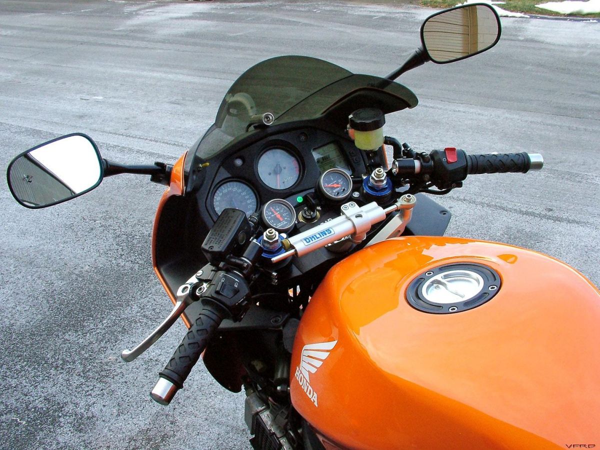
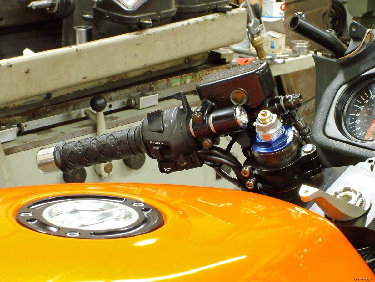
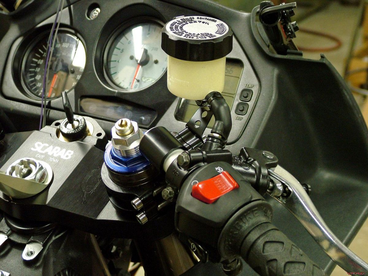
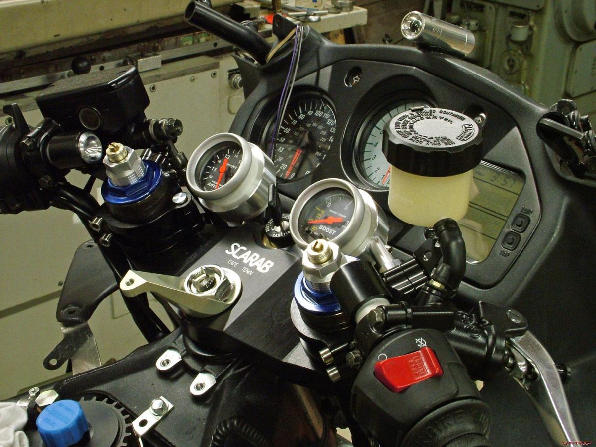
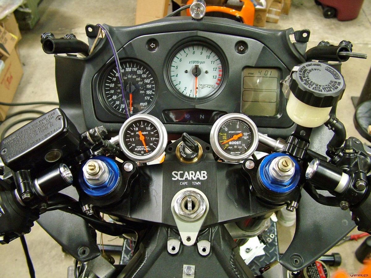
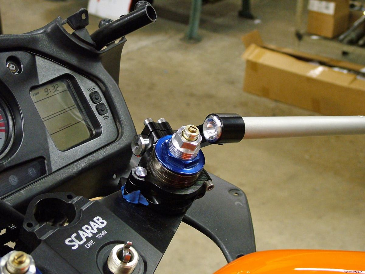
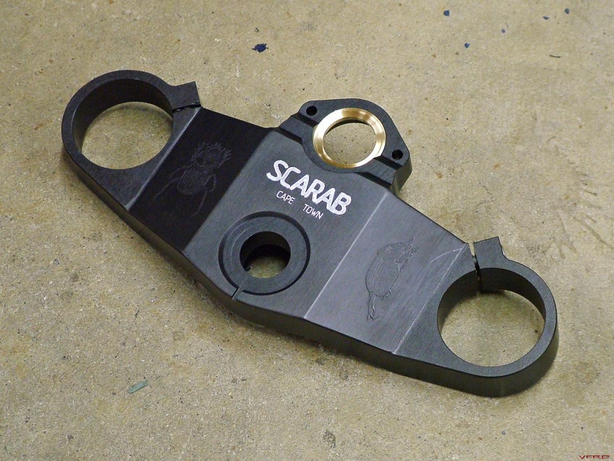
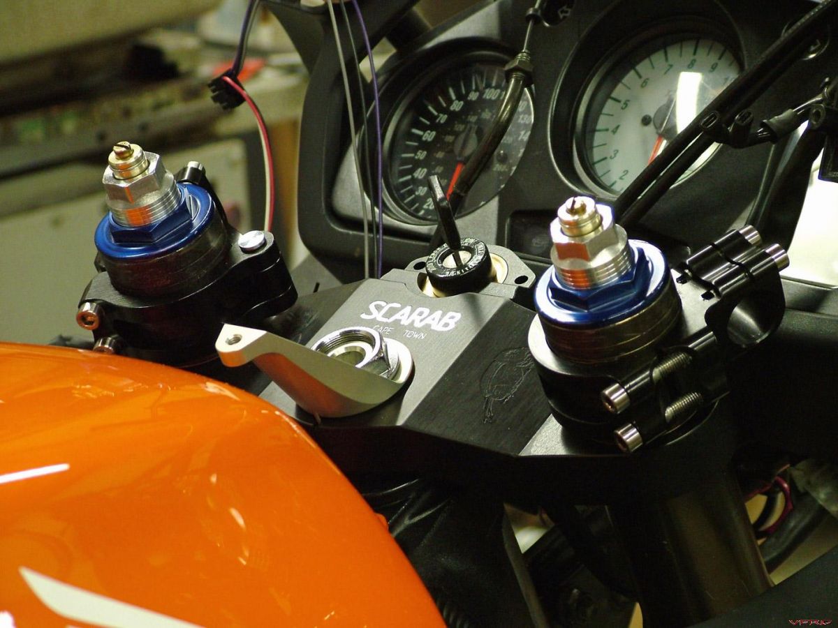
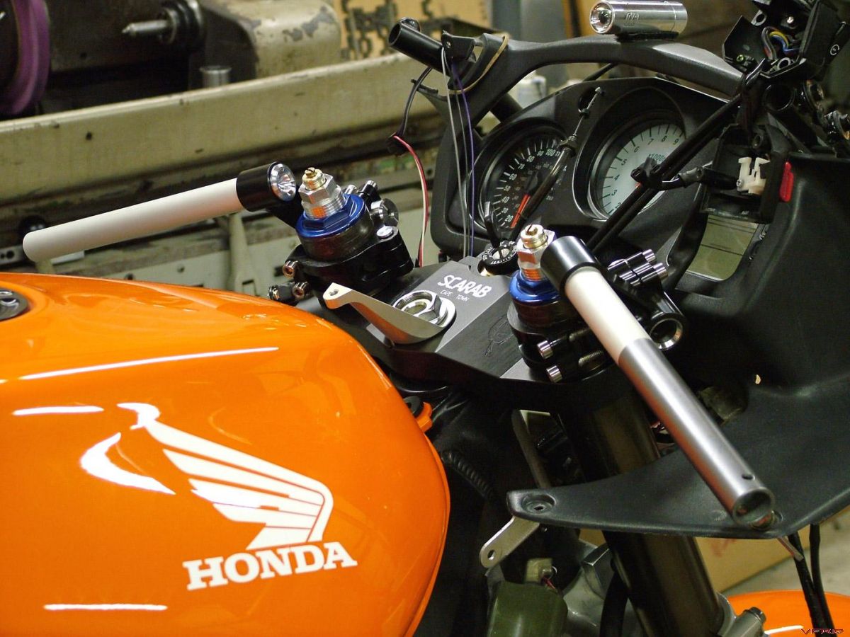
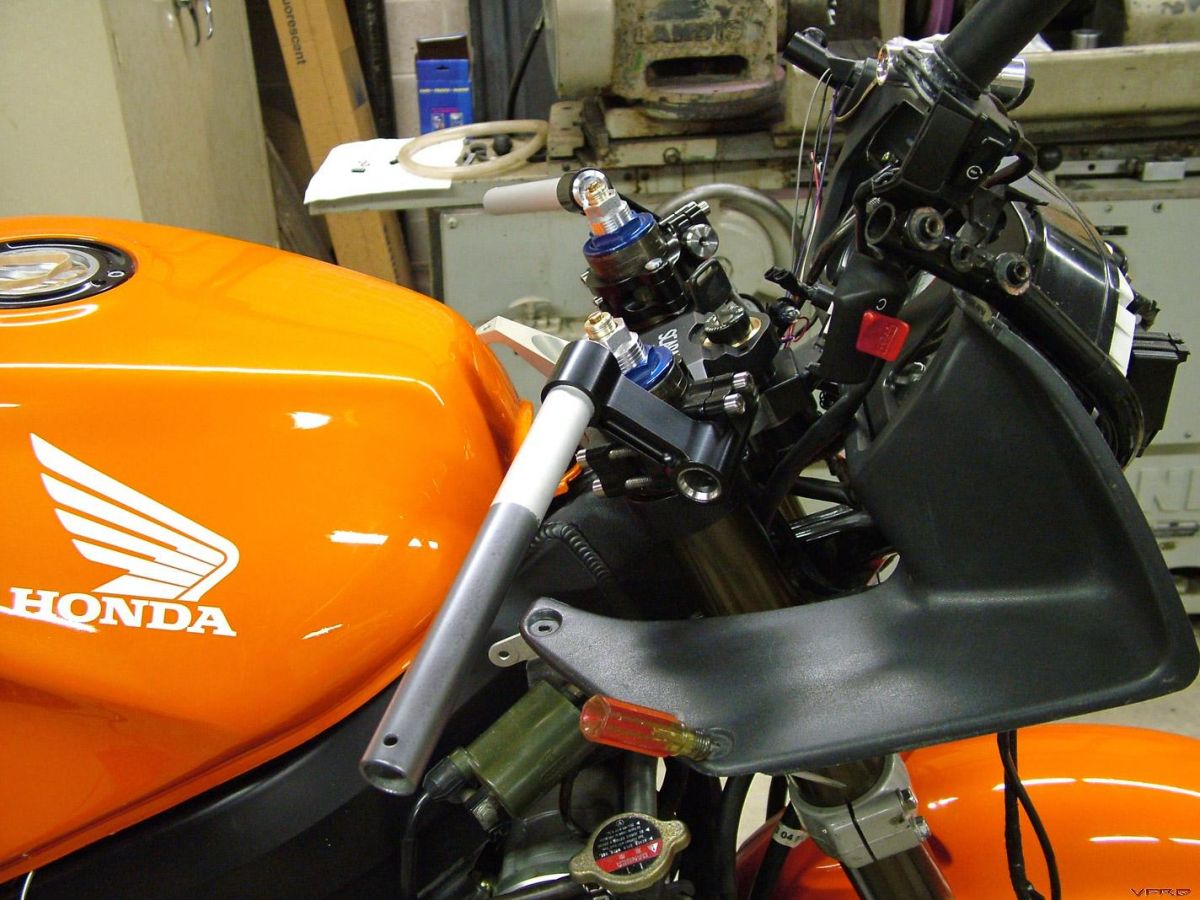
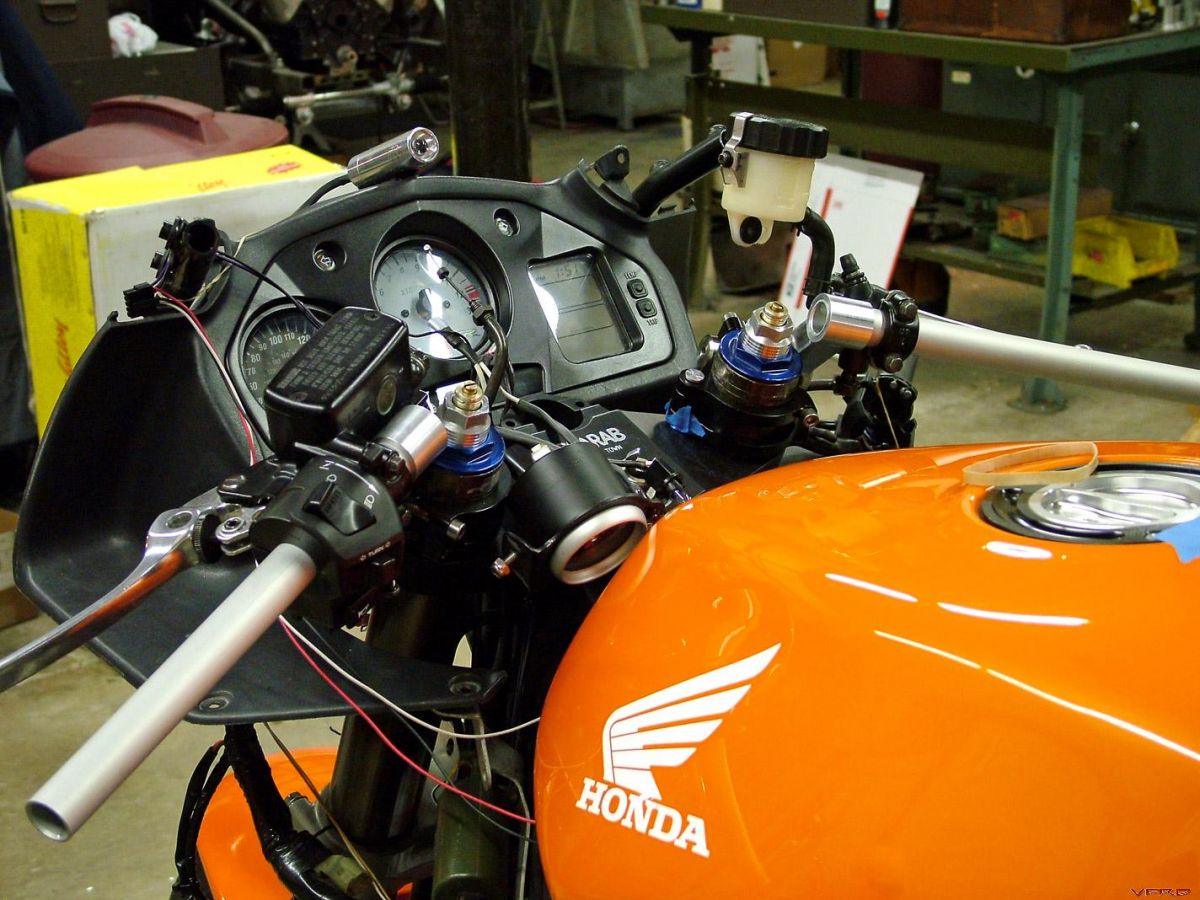
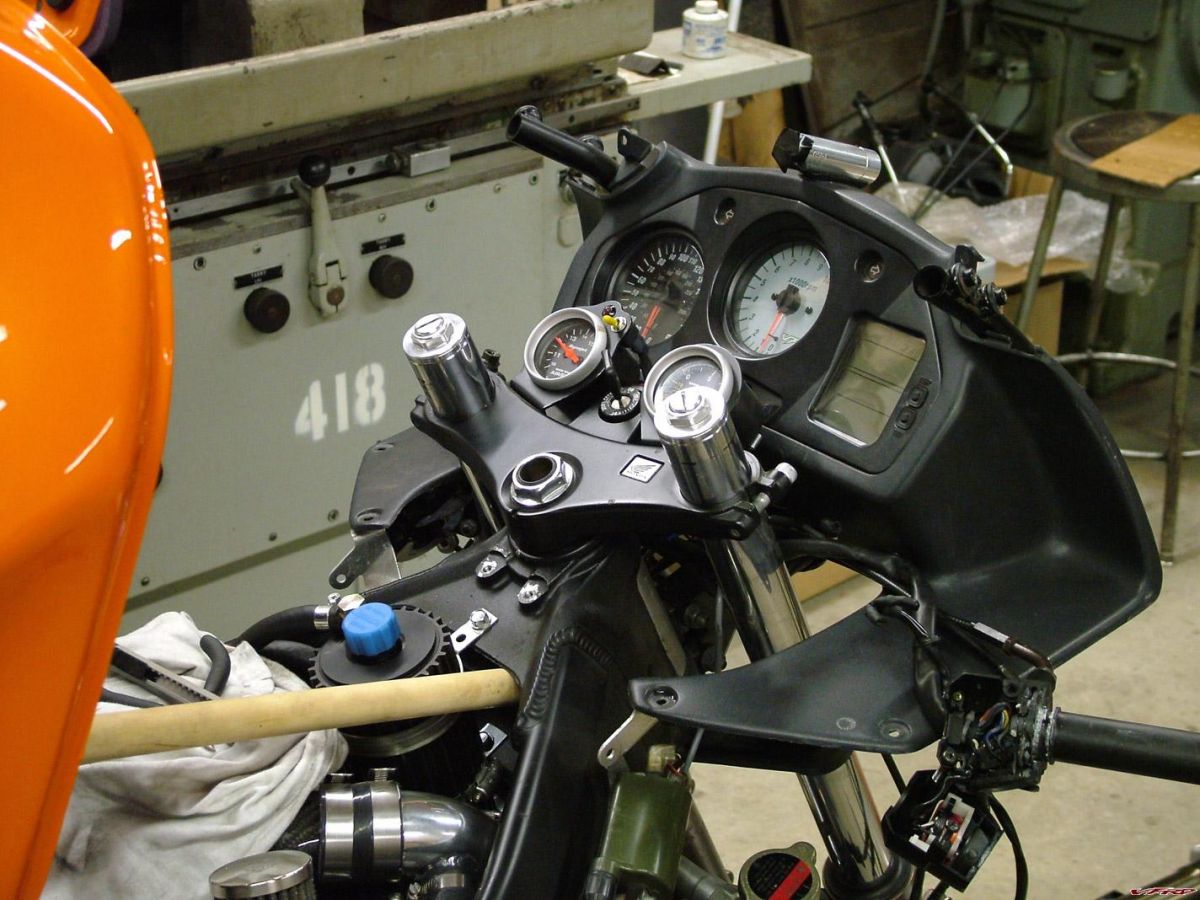
I decided to paint the gauges and mounting brackets black...
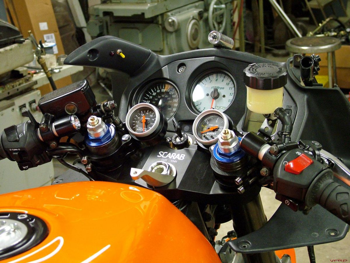
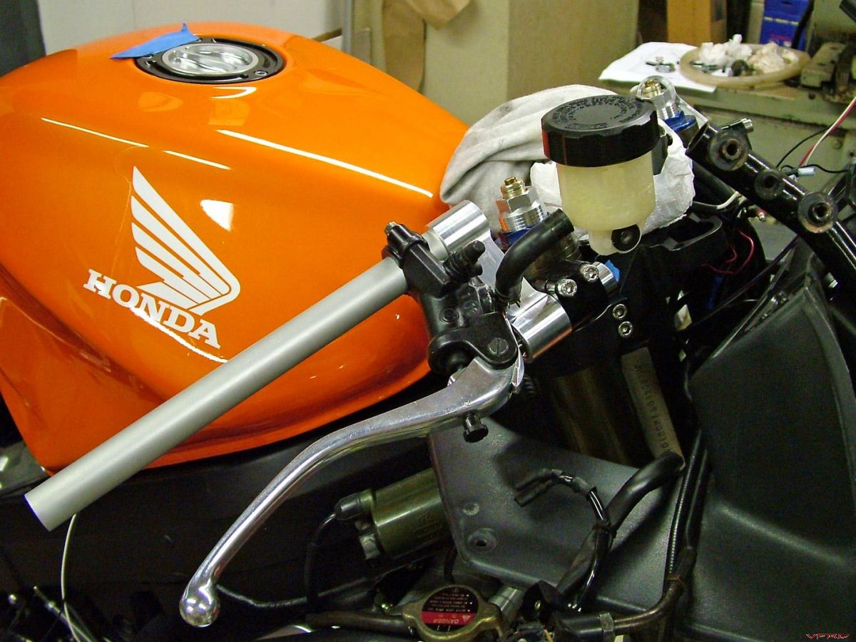
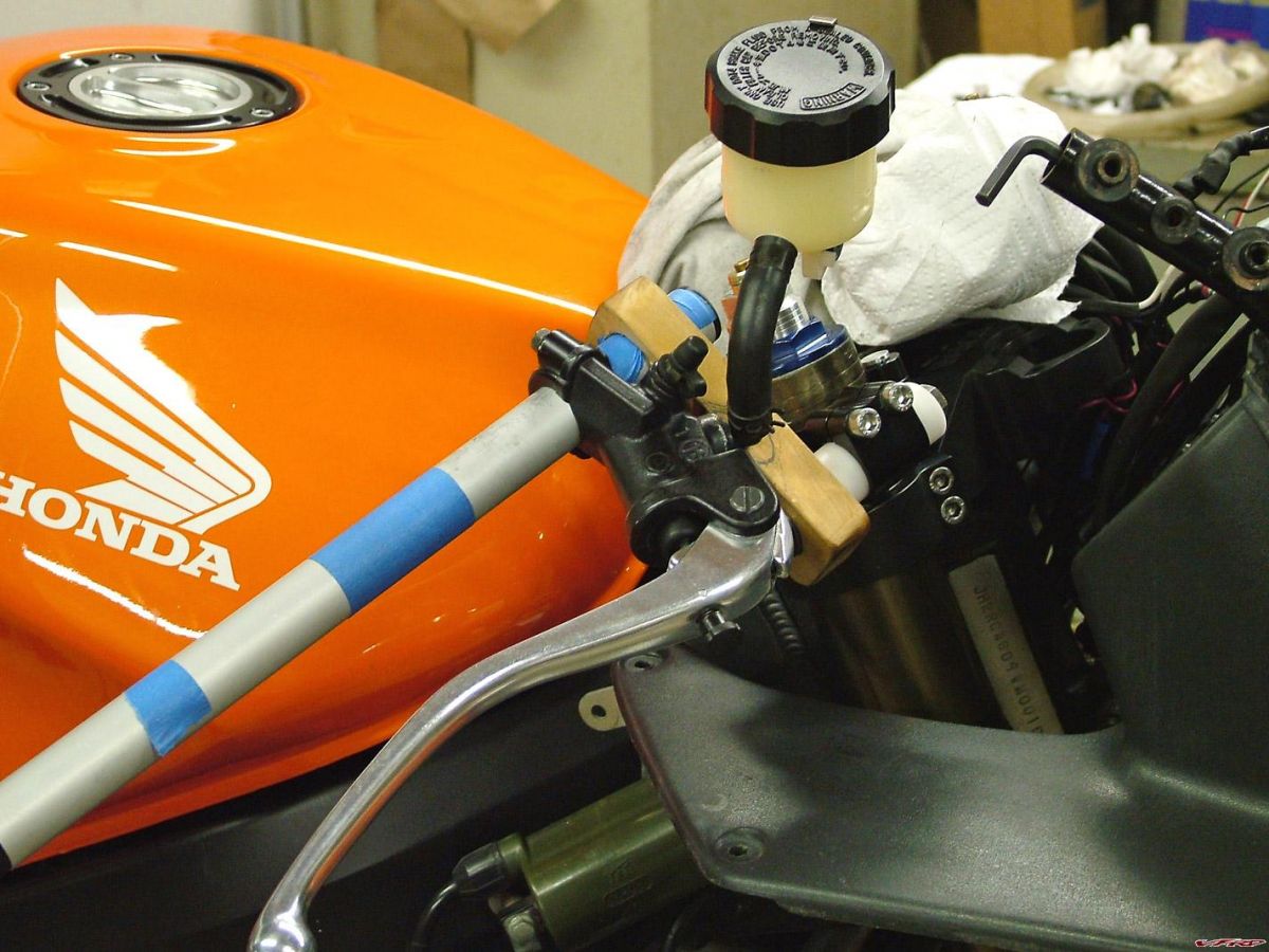
I initially wanted to go with a 2 line brake setup, but decided to go with the standard T-split setup instead. I had a local hydraulic shop make them up for me, and the whole deal worked out great.
The completed cockpit...
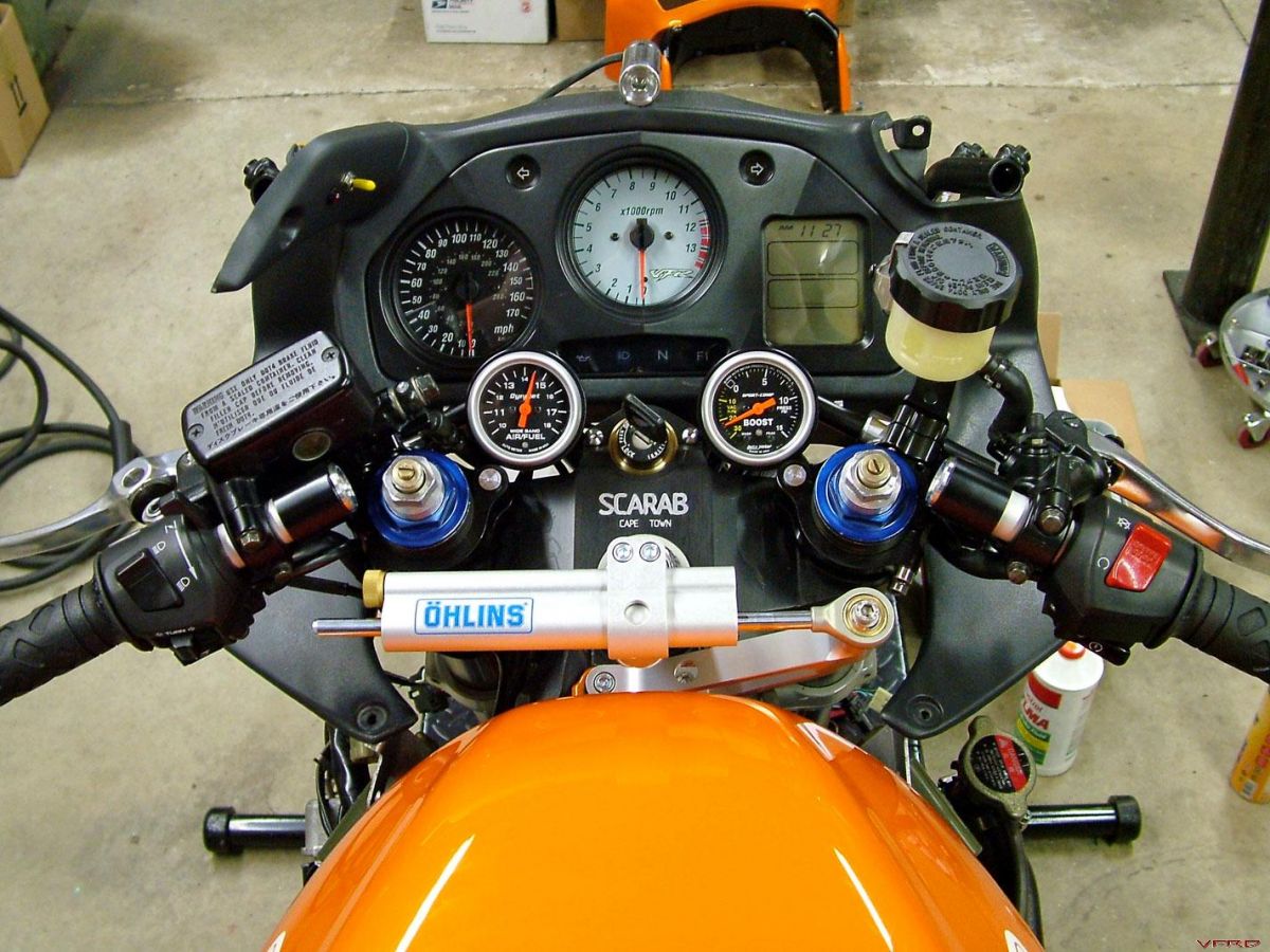
I ran the toggle switch and LED for the Wideband Commander in the pillar plastic this time around to simplify the gauge area. The Öhlins damper was won on ebay for a substantially reduced price and should help tame the new suspension setup. BTW Rob, I filled those holes next to the ignition switch with some stainless button heads, which finishes it off nicely.
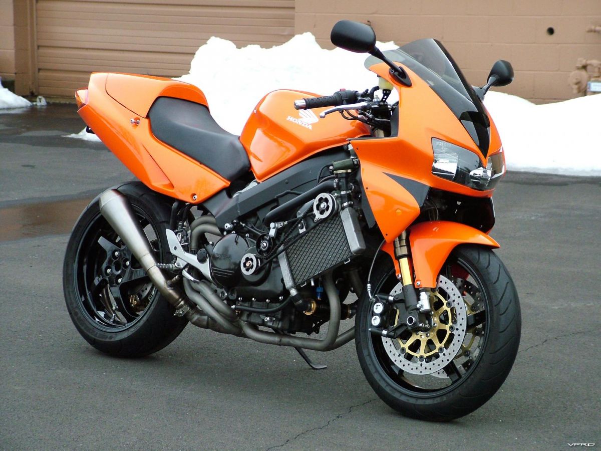
Next up, the obligatory Before & After comparison...
Before
After
It took a lot of work to get to this point, but it's all worth it in the end.
The next step, of course, was taking it for a quick spin around the parking lot to test it out. I set all the adjustments halfway and treaded very carefully...
It was cold, and very slippery, so my ride was pretty short. Initial impressions: The ride is fantastic. The new forks and Elka shock are working together beautifully, and this thing now soaks up bumps like never before. It's like riding on a new bike. With proper damping. The front brakes work well for not even being broken in yet (I was able to lock the front wheel a bit too easily on the salted surface, so I was extra careful), and the rear brake still feels wooden, but will instantly lock the rear tire if pushed hard enough. With the damper turned up, low speed tight stuff is a bit awkward, but once you're moving it feels like our 08 gixxer thou. So far I'm very happy with everything, and I can't wait to go for a real road test.
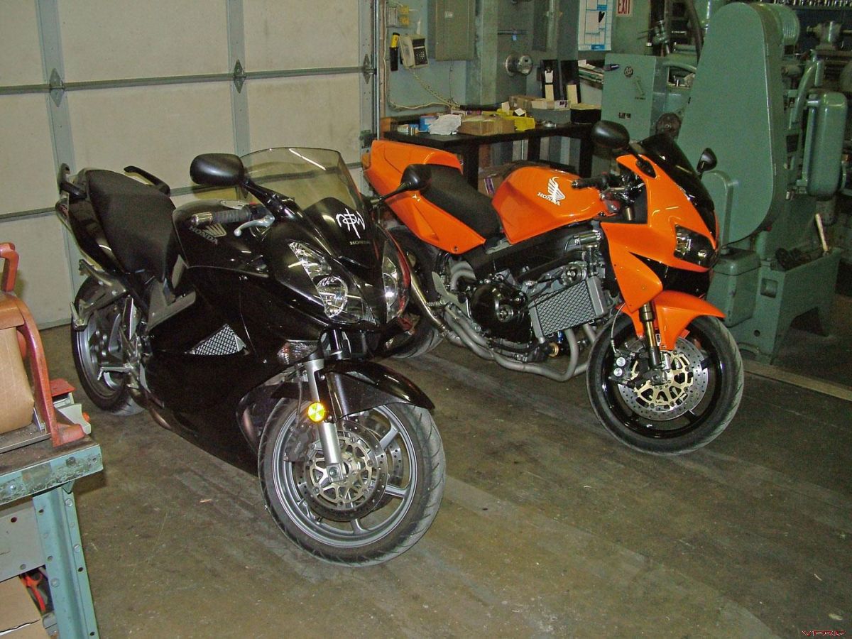
PS - When I pulled back in the shop, another bike seems to have joined the stable. I wonder what I should do with it?
-
looks very nice! I suggest cutting the mounting bolts under the gauges a tad shorter, since you won't need them...it will clean that view up nicely.
You beat me to the punch. I just had the gauges mocked-up in those pics -- it would drive me crazy if the posts were left that length.
-
Some more progress to report...
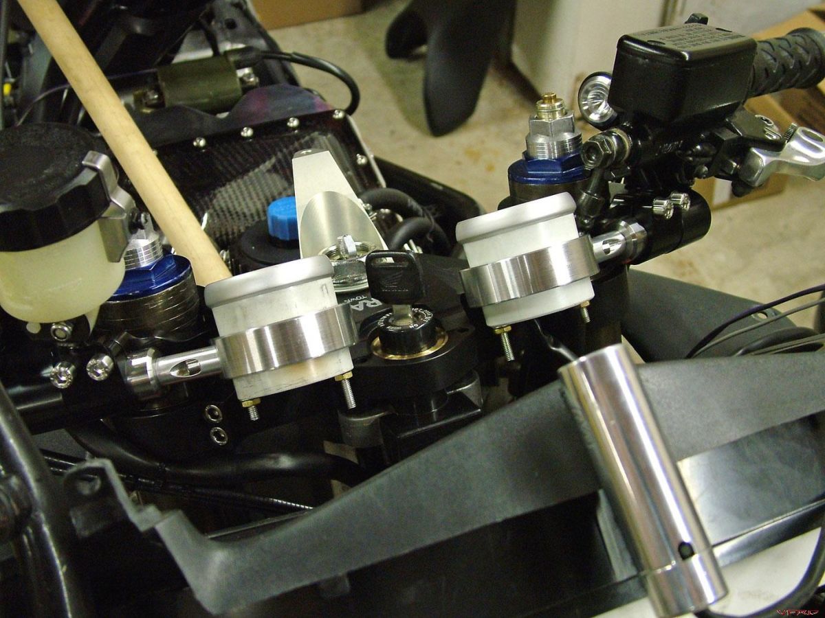
Here's the completed control on the clutch side:
I had to remount the horn, so I was able to bend the existing bracket and attach it to the upper fairing support.
The remote mount reservoir needed a bracket to keep it from moving around, so after first fabbing a mock-up out of cardboard, I made the final piece out of some aluminum sheet and painted it black to match.
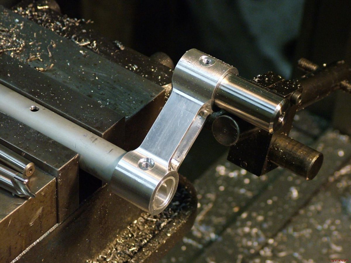
I didn't want to mount the gauges the same way as before, and decided beforehand to instead mount them off the ends of the bars...except I didn't know how I wanted to do it. I came up with an idea to have the gauges sit in aluminum rings, and use angled spacers to connect the rings to the bars.
Making the spacer. The angle matches the offset of the bars, and the one hole had to be drilled and counterbored perpendicular to that angle.
I turned the rings first, and then had to mill a flat on one side to mate up with the spacer. Doing it this way allows me to position the gauges at pretty much any angle I want and gives me tons of clearance away from the dash panel.
I'm still unsure of whether or not to paint the brackets (the gauge bodies will be black no matter what) and where to place the switch & LED idiot light for the wideband datalogger. I also found out that the Galfer brake lines I got such a good deal on won't work due to the spaced-out radial mount brakes -- the lines ended up being too short. Luckily, I found a local shop that will make me custom lines in any length I want.
-
Got the bars all painted...
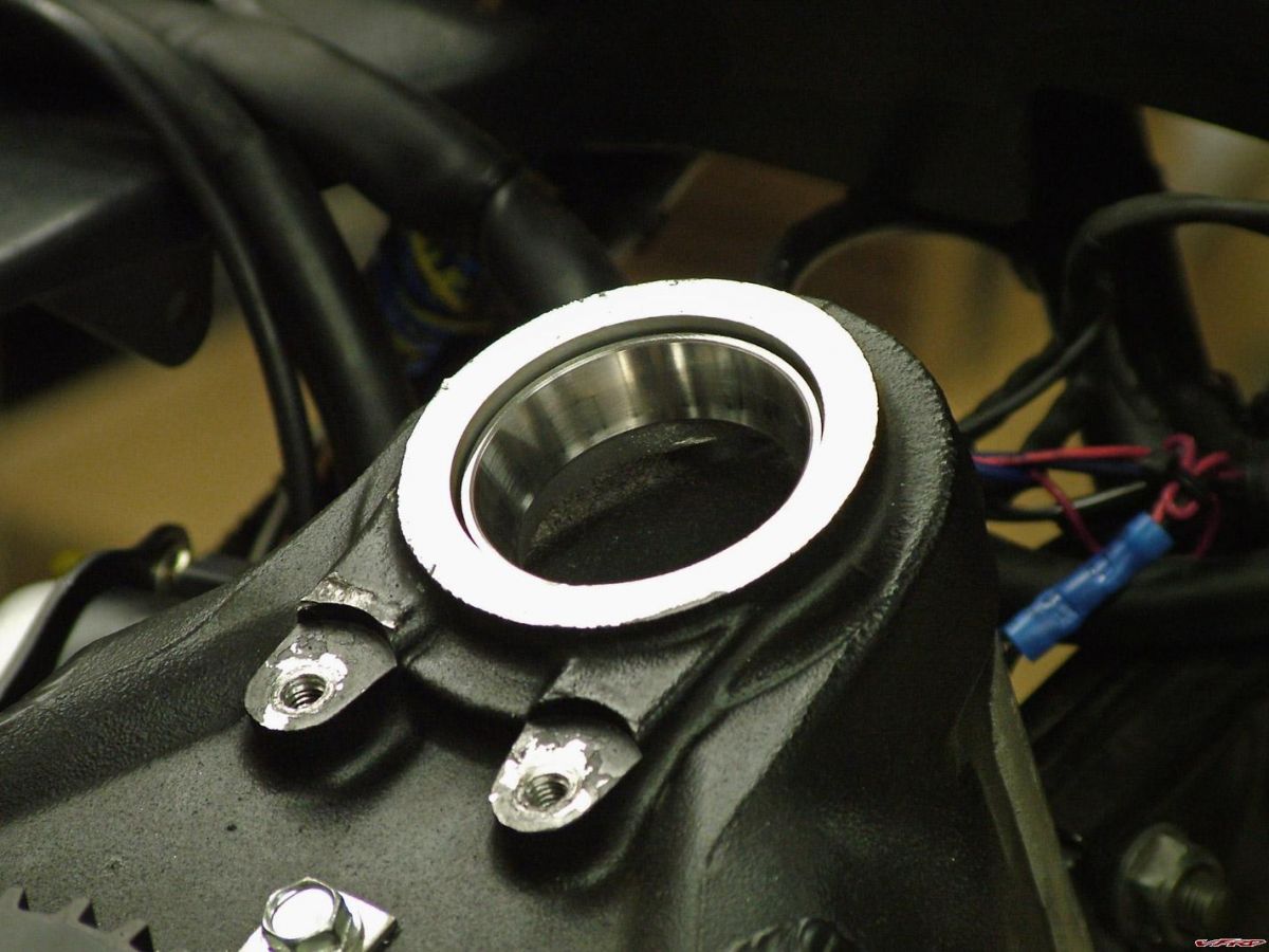
I also turned up a filler piece to get rid of the gap around the ignition switch, and it helps make the top triple stand out a lil bit...
From Cape Town to Huntingdon Valley... All bolted up with the clip-on bases installed as well.
I also added some dry film moly coating to the area where the throttle tube rotates.
The risers pretty much get covered once the controls slide on there, but all bolted up, they are rock solid.
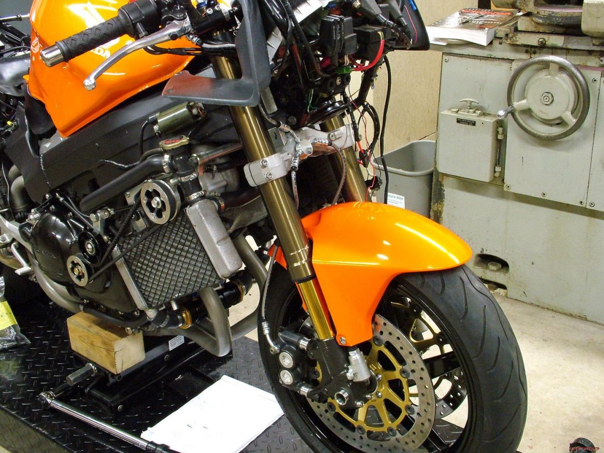
One aspect I'd been unsure of the entire time was the stock front brake line setup that came with the calipers.
I've tried to do things as economically as possible in this swap, and really wanted to keep this line setup, but after I made a stainless bracket, drilled and countersunk the lower triple, and got it all bolted up, I realized it wasn't going to work. It's close, for sure, but there just isn't enough space between the fender and the mounted hard lines for me to be comfortable, and the lines are too short to move them up further -- I've got a (new to me, but still used) set of aftermarket lines coming as we speak.
-
So when are you going to start working on the 6th gen then :fing02: ?
Well, as soon as I can find someone who wants a kit and is willing to donate their bike, I'll start working on the 6th-gen. I had a few different guys lined up, but they had to back out for one reason or another. So...if you've got a 6th-gen, want a kit, and would be willing to be the guinea pig, let me know.
How much would a set of these bars and risers run if someone else would like to use this mod?Boy oh boy, I don't know. I did it this way because 1) I wanted maximum adjustability due to the unique nature of my setup, 2) I didn't want to spend a lot and had a CNC sitting in the other room, and 3) I already got a great deal on the Attack clip-ons.
So, if you swap to an RC51 front end and then end up getting the Attack clip-ons, give me a holler.
-
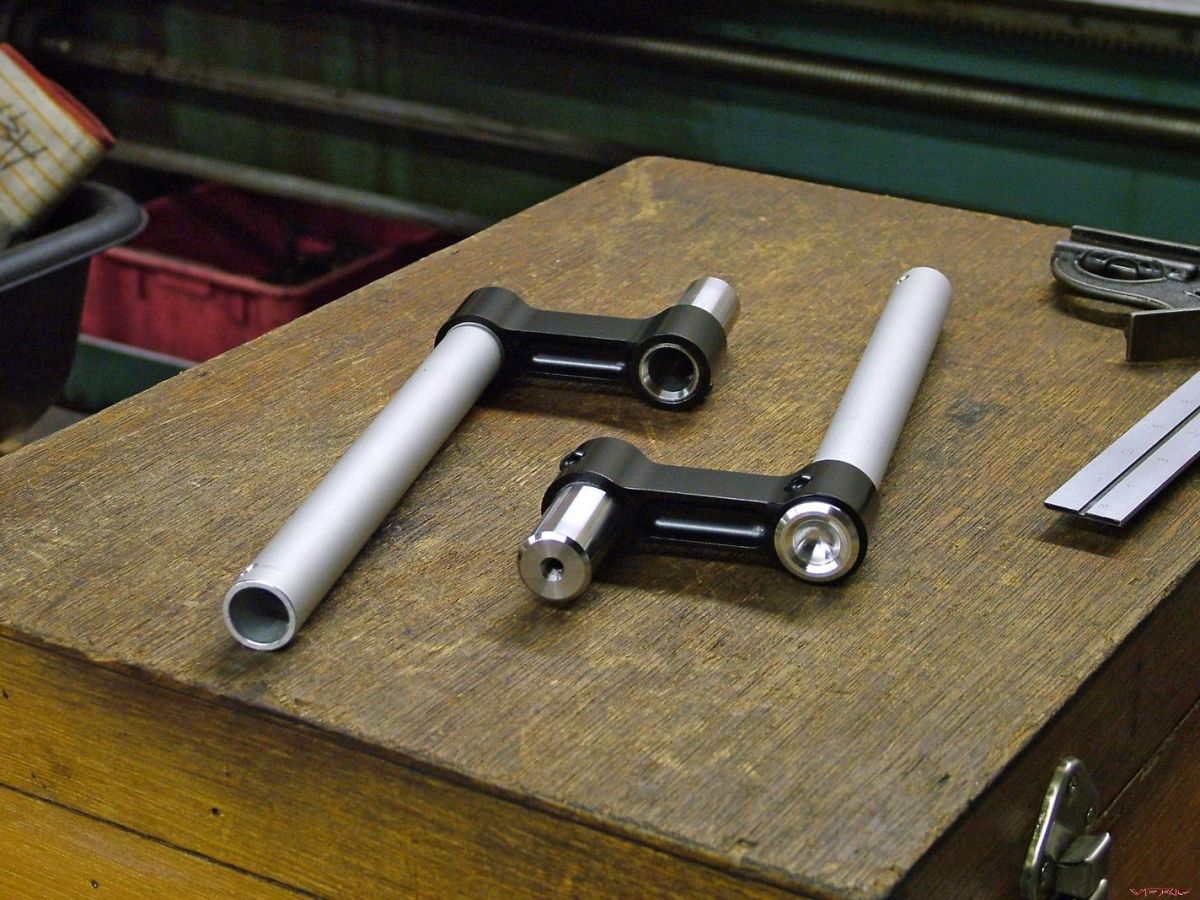
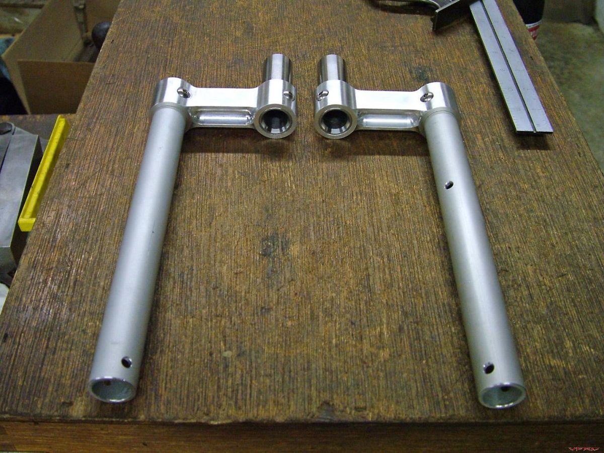
The bar riser bores were designed to be an interference fit with the bars, and after creating the lower adapters, I pressed them together.
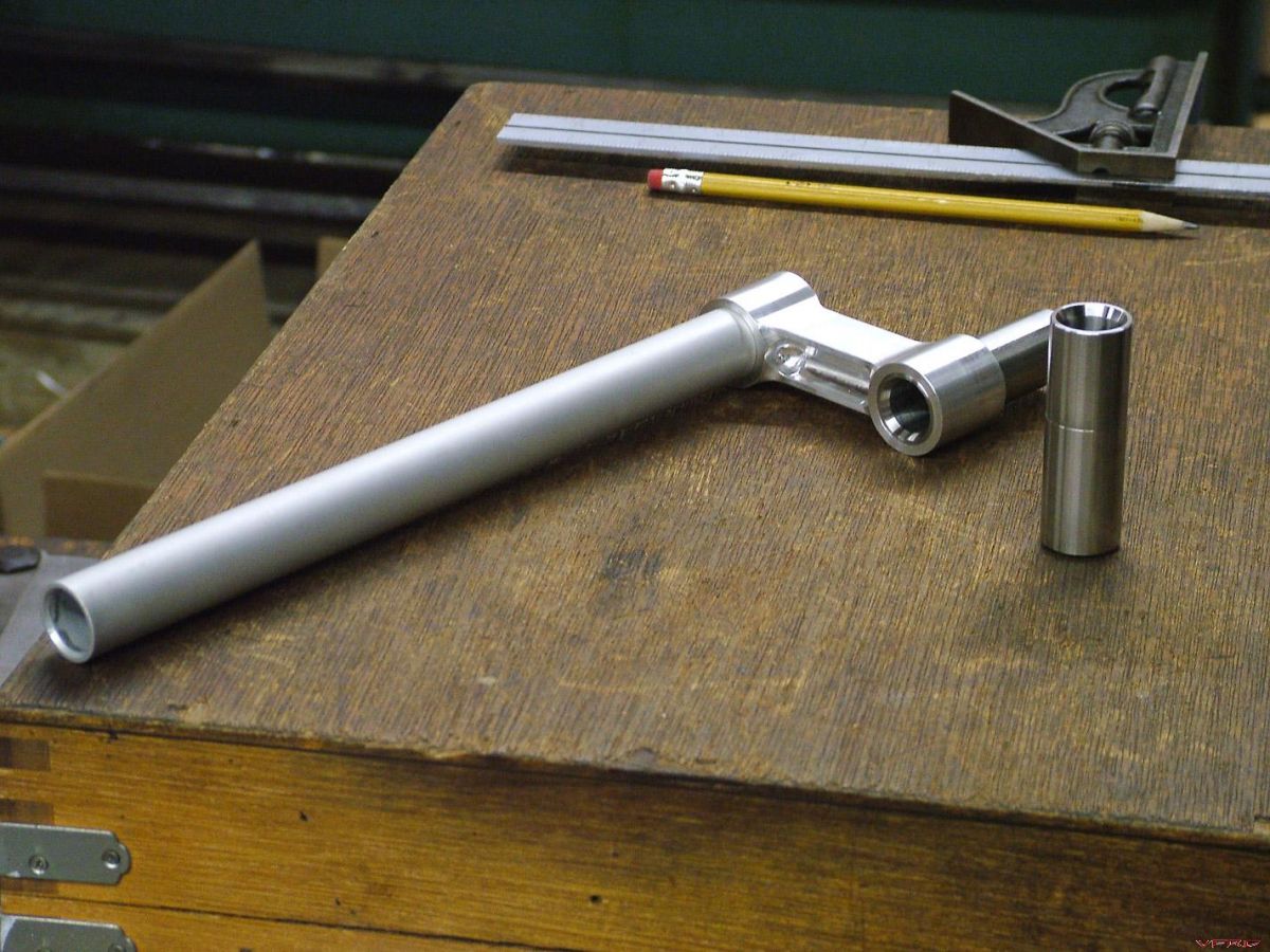
The next step was to check fitment and figure out where the holes needed to be drilled for the controls. I'm also retaining the original bar weight assemblies, so holes needed to be drilled for them, as well.
Even with a .0015-.0020 interference fit and Loctite retaining compound, I still wanted to pin the bars, just in case.
I cut the bars to the right length, installed some M5 button heads, and voilà, all done (well, almost, I still need to paint them black).
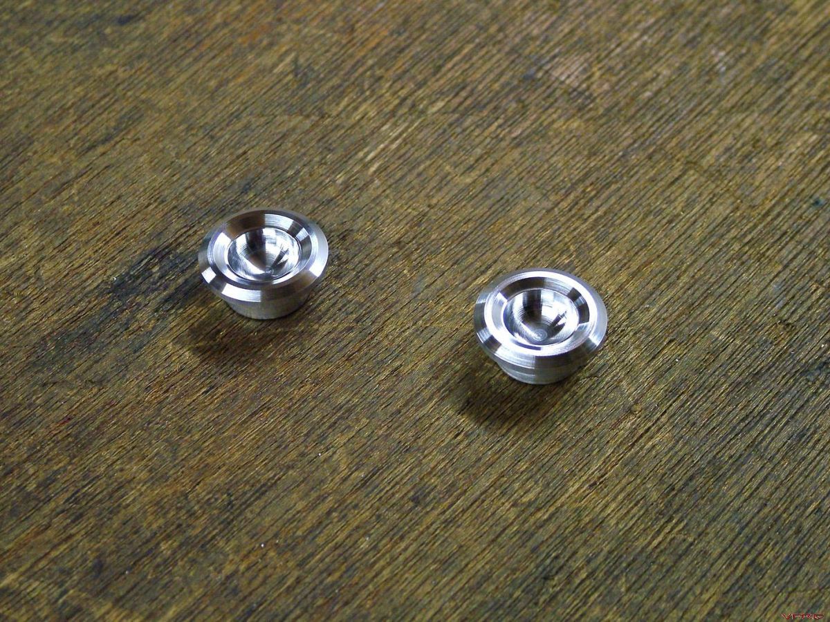
The final finishing pieces to the bar puzzle are some spiffy little plugs for the open end of the bars.
The only things left to do now are mount the gauges, finish the wiring, make a few brackets, bleed the brakes, and put it all back together. Shouldn't be too long now... :fing02:
-
To those of you unfamiliar with CNC machines, here's the process that allows you to go from a solid block of metal to functional parts...
First off, you need to draw up what you're going to machine -- for most parts I use AutoCAD. After the design is finalized, you need to write a program the machine can run, which in this case means importing the geometry into a CAM package, generating toolpaths, and then creating G-code (which is the universal language for CNC machines).
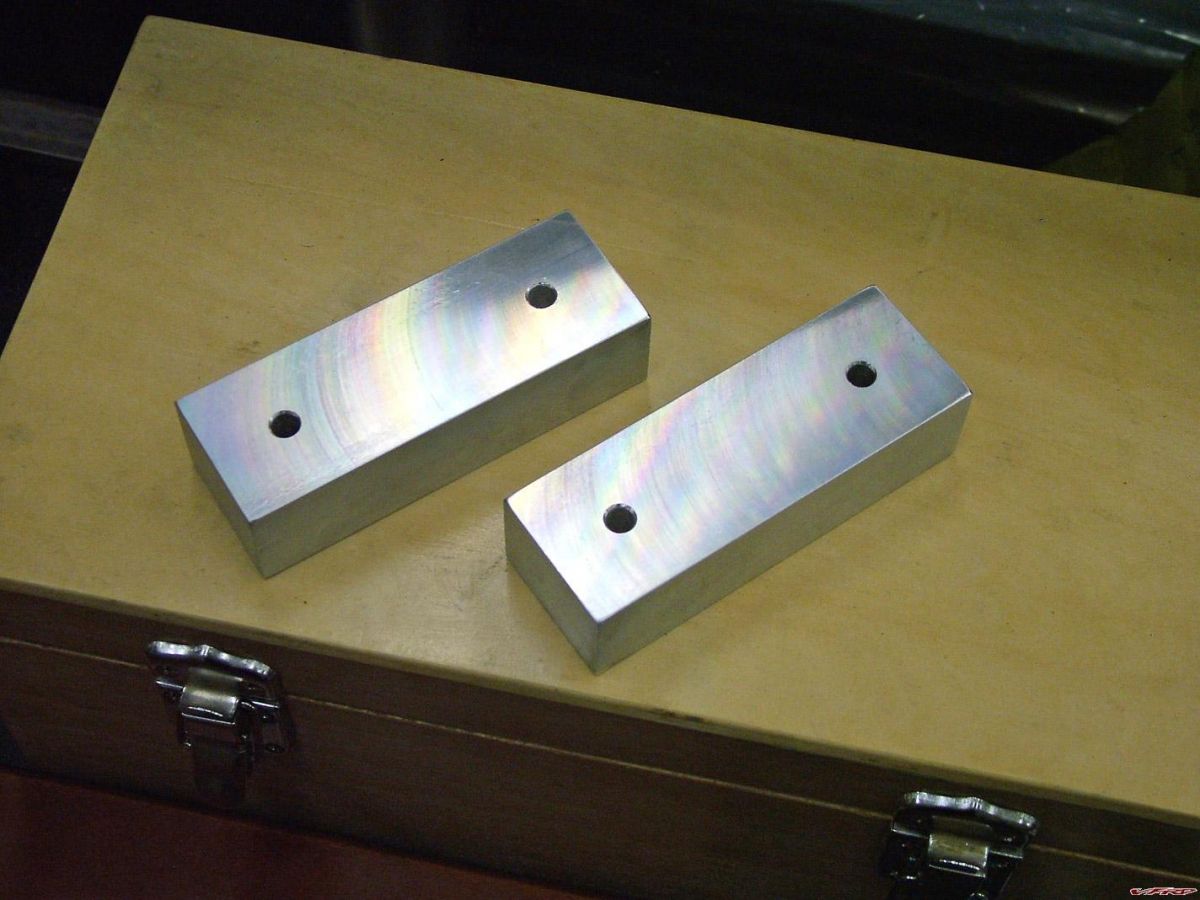
So, starting with a 12" block, I sawed up some blanks and then faced them to size...
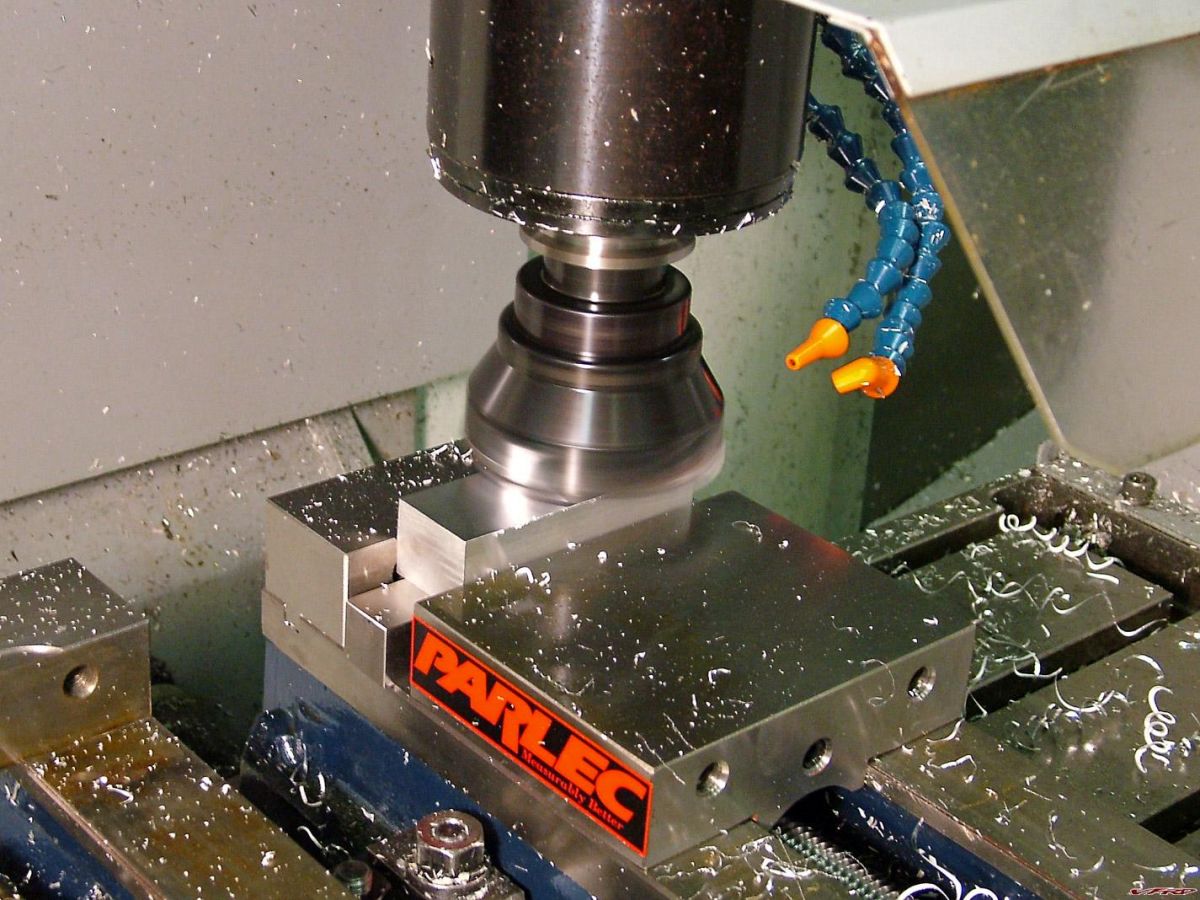
I also needed to add two 1/4" holes to mount them to a fixture (which I also made). Then, it was cutting time...
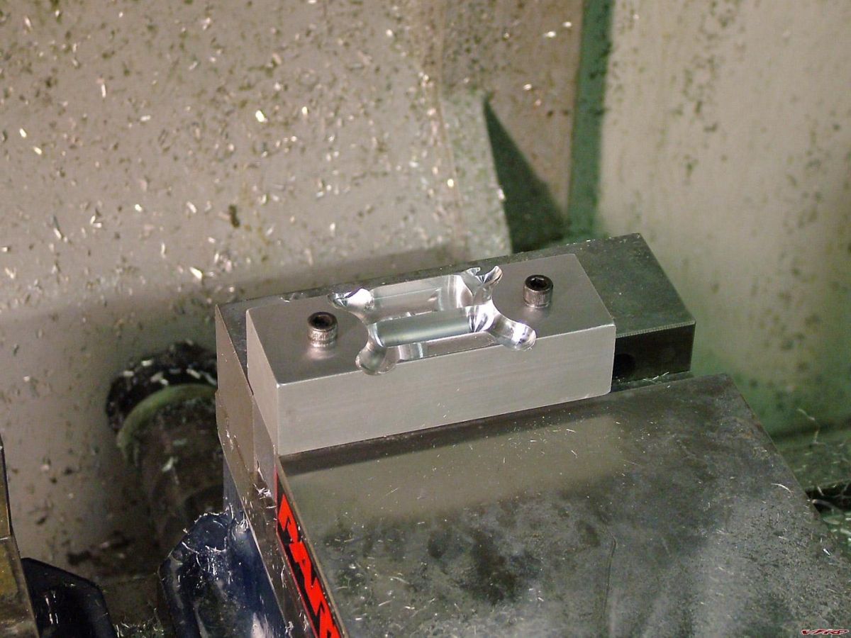
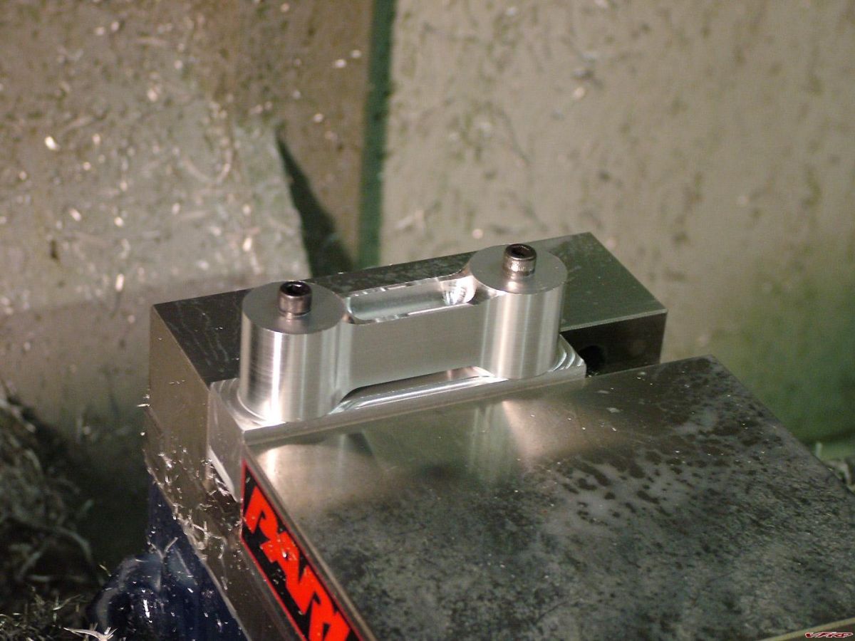
I programmed it to do both sides and then contour the outside. Once that was done, I removed the fixture, clamped on the sides, and machined the bores.
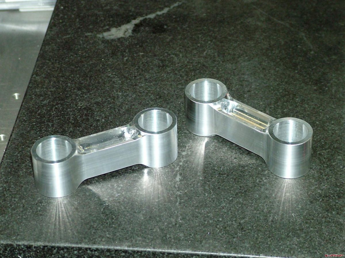
All done. The next step will be mating the bars up to these risers.
-
I am straying from the topic but.. I need to ask... Have you done live tests against liter bikes, such as roll-on, quarter-mile, top speed etc ? Enquiring minds need to know... :fing02:
Well, uh, I've done one such "test" against an RC51 from a stop, and here's how it went -- neck and neck through 5 gears as the front end was just a little bit light (translation: :unsure:), and once settled back to earth, I just pulled away. Back when the bike was in its original weak-sauce 145whp guise, I rode around with JES and his '01 VFR800. Maybe he'll chime in and give you a ride report...
From a back-to-back ride comparison between an '08 GSX-R1000 and my bike, around town it's no contest -- the gearing of the VFR makes it a lot more fun to ride as the power is just there instantly. The GSX-R puts the power down better (that is, keeps the front end on the ground), and as such would be better in a drag race, but the sense of acceleration going full tilt is pretty much the same between the two of them, with the nod going to the VFR in the "scary" department.
As for the ZX-10R we just supercharged, well, the bottom end is somewhere between the VFR and the GSXR, but the sense of speed is just ridiculous. The powerband actually feels just like my VFR, but you are going faster in every gear. Much faster. The top of 4th gear comes up so quickly that you can hit it even on an average stretch of pavement, at which point you're doing nearly 150mph (but then again, that's what 220-230whp will do in a 410lb bike).
-
I'm curious, what do you eventually hope to do with the bike? Are you gonna turn it into a track bike?
Nope, I just want to ride & enjoy it. I've been spoiled rotten by the literbikes' handling and want to get closer to that with this bike -- basically put the emphasis heavily on the sport side of sport/touring (and I've already got the acceleration nailed). No matter how radical I get with the suspension & riding position, it's still going to be more comfortable than modern supersports, which is where I want to be. Plus, the RC51 swap was something I wanted to do before I even got the bike.
-
Ps. what did you do about the spacer to make up the difference in height between the bearings? Pete Mc Crary has a thread on this spacer right now.
:biggrin:
As this front end was already on a VFR, I had to do very little research with regards to steering bearings and spacers. It's an SP1 lower triple that was already modded to work with a spacer. I just had to replace the bearing races and slide it in.
From this angle, it almost looks like your fender is going to hit the lower triple under hard braking. What measurements did you take before you set this all up?It's an optical illusion Seb. While close, even if the forks compressed down to the seal (which they don't), it would still be 1/4" away, which is a mile in my book. I measured fender to fairing clearance, the distance from the bars to the ground, the neck to the ground, and the bars to the neck (I'm most concerned with the fender to fairing spec).
-
I´ve also heard over the years that stainless bolts are not to be used in places where there are torsional stresses on them ie. rotors, calipers etc, but they are fine for engine cases and the like.
It all depends on the forces involved and the quality of the fastener. ARP & SPS make some extremely high quality, high strength stainless bolts that would be perfectly fine in this application. In fact, if you took the time to do a full free-body diagram analysis of the brake setup, you would get a pretty good idea of the forces involved.
So let's simplify things and see if we can get some numbers...if we assume ideal traction and completely discount the added effects of friction force between the caliper bracket and fork bottom, here's the worst case scenario...
Imagine the bike's mass to be ~450kg (basically, fully fueled with two 250lb riders). Now, imagine you are to slam the front brakes on as hard as a GP bike and are somehow able to manage 2g's worth of deceleration -- this means a torque of 2750 N•m would be applied to the front wheel. An M10-1.25 bolt has a minor thread diameter of 8.25mm, with a cross-sectional area of 53.52mm2, and since we know the distance of the bolts from the center of rotation (~42mm & ~96mm), we can compute how much load each bolt will see.
The highest shear force would be encountered in the bolt closest to the axle, so: 2750 N•m / 2 brakes / 2 bolts per bracket / .042m = 16400 N. Now, regular old A2 (18-8) stainless bolts have a shear strength of ~310 N/mm2, meaning the max load they can support is 16600 N (in an M10-1.25, that is). What all this means is that even with the completely ridiculous assumptions I'm making, the bolt is still technically a little under the failure limit. Considering braking forces don't even approach 1g on a streetbike (thus halving the moment on the front wheel), I'd say these bolts would actually be usable in this application.
Having said all that, I'd still use the 12.9 bolts to hold the bracket on. What the numbers don't take into account are impurities in the material and/or stress concentration points due to poor machining if the bolts are not quality pieces, so any way you can increase your chances with something as important as the brakes is a good idea to me.
Thanks for the brain exercise, Bren. I think (hope) it makes sense :fing02:
-
That would be the first OEM use of M10x1.5 thread on any modern Honda I've ever heard of! Gotta be M10x1.25... Maybe you were confused, with all that "foreign" SAE hardware you spec'ed on your supercharger kit!

You're probably right, John. I know the crank bolt is M10-1.25, but I guess I'm just too used to the M10-1.5 hardware associated with the Rotrex -- the Danish must like their M10 threads coarse...
...and hey, what fun would installing a supercharger kit be without having all different kinds of hardware?
-
Oh BTW, how do you like the fuel filler cap?
Is that one of those cheap Chinese units from Fleabay?
I was looking at them the other day, thinking......
Nope, it's a Vortex unit. I screwed up the paint on my original cap, so on it went. Looks wise, it's great -- you can get whatever base and cap color combo you like. Weight wise, it's no contest between this and the stocker -- Honda: 1 lb, Vortex: 1/4 lb. Function wise, eh, the stock one is better. The threads aren't the greatest on the cap, so you need to keep them oiled, and as far as actually filling up the gas, you always have to find a spot to rest the cap (and hope you don't drop it).
If I were to do it again, I'd probably go with one of those 1/4-turn jobs with the smaller cap, but then again, most of those are 3x the price of the Vortex.
-
Here's a shot of the bar riser mockup...
With the bars and controls in this position, everything clears lock-to-lock. Now I just need to draw up the risers in AutoCAD, program the toolpaths, and spit them out on the Haas.
-
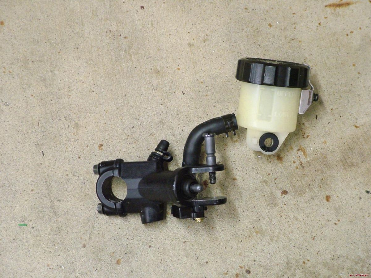
What about using a Honda master cylinder with the same I.D. as the Yamaha part?
Then, you'd have matching reservoirs on both sides without clearance problems?
I thought about that, Rob. I really like the thought of a radial Brembo MC on there, though (which the Yamaha unit is). The biggest issue is actually more with the lever than the MC body, as the lever on either design sticks out about the same amount. I'll post up some pics later of how I plan to rectify the situation.
Now, if I felt like swapping a different gauge cluster on there and getting rid of the big inner plastic panel, there wouldn't be any clearance issue and I'd end up with a more aggressive riding position, but I think the risers are the correct path to go here.
-
Could you use your delink project to answer a question of weight change on the RC46? Basically save all the parts that the delink makes redundant and then throw them on a scale?
I know that you're changing front calipers but the weight difference would probably be pretty minimal, basically the extra hoses and all the other hardware that you're able to drop and don't need to replace with a like part, that sort of thing. Then we could point to your answer and say "okay, here, it only saves X pounds to delink" when asked in the future.
Please?
Yeah, I can do that for you.
-
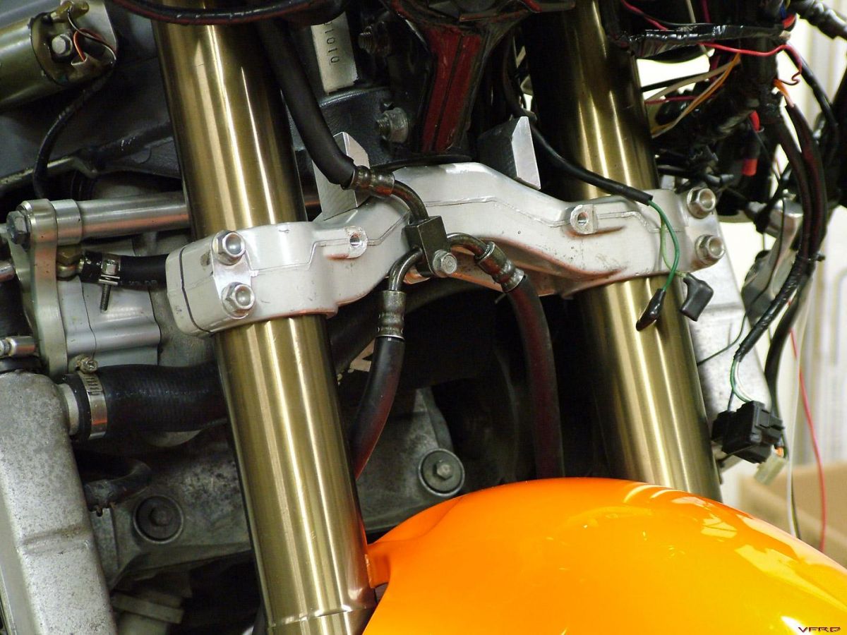
I think it's time to get that front end mounted...
...but I need to get that old one off first. This is the final look at the old setup.
I needed to swap bearing races to work with the new tapered roller bearings of the RC front end, so I tapped the old ones out, and pressed the new ones in.
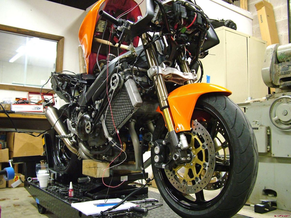
Positioning the complete assembly into place. So far, so good.
I had to rebuild the master cylinder as it was in pretty poor shape from sitting over the years -- now it's good as new. I also had to reuse the stock VFR lever pushrod as this was missing one (of course it was too long and required some modification). The big question in my mind was if the master cylinder would work with the bars...
In the process of setting the ride height. That looks just about right. :laugh:
Definitely more aggressive than before. I put the upper fairing on there to check for clearance, and with the bare bars, everything is fine. However, once I installed the R1 radial mount master cylinder, I had clearance issues with the gauge cluster. Luckily the bars I'm using are modular and should be pretty easy to make work in this application; I'll throw up pics once I get it done, but I'll have to make a pullback riser to raise the bar slightly and bring it further back.

Want my bike? The first $289 takes it!
in Body and Paint
Posted
I had to post this. Hong Kong is now offering a 5th-gen bodywork package painted in a shade very reminiscent of HOK Tangelo.
Click here to check it out.
I'm not sure who owns the bike they used for the display pic, but it does have a familiar black V up front and HONDA on the bottom. It kinda blows my mind when I think about the chain of events that had to unfold for this to exist...