


pres589
-
Posts
265 -
Joined
-
Last visited
-
Days Won
1
Content Type
Forums
Profiles
Gallery
Blogs
Downloads
Events
Posts posted by pres589
-
-
Anyone out there know what the ECU thinks about having the MAP sensor pulled out but the rest of the system wired? I figured out that the side stand "sensor" was shunting to chassis ground when the side stand was up, which caused the ECU to fault entirely, with a single solid FI light on. Disconnecting the side stand from the bike entirely has fixed that.
I had a single blink and then eight blinks of the FI light after that. A single blink is MAP sensor failure, eight is TPS. Looking at wiring schematics, some of the MAP and TPS wiring from the ECU is common. I've run through MAP sensor testing and instead of dividing the 5V reference signal from the ECU into something like 2.7 to 3.3V as per the manual, it's outputting 0.3 volts as measured from the middle pin on the MAP connector to chassis ground. I have nice clear 5V on the supply wire as I should, and a good continuity on the ground wire, so this sensor seems clearly trashed.
With the MAP sensor off the bike entirely I still have eight FI light flashes. But I had those before. Thoughts?
-
I've been back at it with this bike and I'm about to give up. New stub harness that attaches to the injectors and sensors, new main harness, and now I have an FI light that stays on constantly. Both harnesses are doing this now. I really wish this bike would get stolen somehow, and no, it's not insured. Not sure how to proceed and tired of messing with it.
If I knew I wouldn't be sitting on boxes of parts for a year I'd start parting it out tonight. But it's VFR bits so I doubt any of it would move any time soon.
-
New ECU didn't really change anything. The last stop is the wiring. I either replace harnesses or try and make my harness exactly like factory. Not sure which sounds like the best path, probably harness replacement.
There may also be something to some other sensor changing the ground path or the 5V+ reference path in the harness.
Basically I think I need to get the harness and attached components back to factory and see what happens.
I bet someone would love to sell me a perfect 2003 to 2004 VFR engine wiring harness, right?
-
I've ordered an ECU via ebay and should receive it on Friday. I'm really doubting this is a wiring fault and will skip that previous idea of replacing the engine harness. Will update again when it shows up.
-
digitallyhip: What about the wiring harness, specifically the engine stuff, what's that like on your bike?
I want to say I don't need an ECU and probably don't need the wiring... but I'm starting to go into shotgun everything mode on this thing.
How's it going parting out your 2003?
-
The more I think about this the more I'm looking towards reason why I have to rotate the sensor blade to install the TPS. The closed throttle voltage is jacked way over what it should be, by 2 to 2.5 V. With the TPS in my hand the levels are much closer to what they should be.
Both assemblies are doing this and the cables to the throttle tube are disconnected. The butterflies are shut and nothing is hanging up.
Gritting my teeth thinking about this.
-
What the video shows, I think, is that the Dorman and OEM TPS act basically the same (there's some very minor differences that shouldn't affect ECU logic) when handled free from the throttle assembly. The Dorman acts like the OEM did when installed; the TPS to throttle shaft interfacing blade has to be rotated slightly to install the TPS, which swings the voltage dividing wiper inside the TPS, so the voltage is already on its way up from the "closed" state. And this is done without throttle cables attached, which is why I had to walk around the bike to rotate the throttle shaft.
I then lay CandyRed's throttle assembly on top of mine just to wire its TPS to the bike's connector. It does the same stuff as the Dorman when the Dorman part was installed on the stock throttle assembly.
You wrote; "If the ECU is getting more voltage than it should when the TPS is at its highest resistance (that is, closed) then it must be finding some other way of getting to the ECU. How that could be attributed to being attached to the TB vs. not is a mystery." <-- when I install the TPS's on the assemby I have to hold the blade slightly rotated to engage with the slot at the end of the main throttle shaft. The TPS is basically being held at a part-throttle level of voltage output. The weird thing is how both assemblies are doing this. And I'm not been able to fix that. The ECU seems unhappy with anything I do, TPS free and rotated by hand or when the TPS is installed on the throttle assembly.
This seems like it should be an easy fix... I appreciate the feedback and ideas from folks here so far.
-
Okay, this shows basically what I've been dealing with. I know I read the voltages to the camera a bit off (decimal/millivolt conversion error) and I'm kind of not an awesome narrator; this was on the fly.
Thoughts? Make more sense as to what I'm up against?
-
I had a single FI lamp flash and then eight. I pulled the coolant sensor connector off and now I just have the eight. Nothing has changed or improved that I can tell.
I've no idea what to do next.
EDIT: Anyone have a spare ECU lying around for a 2004 VFR? I don't know what other years interchange, I think there are differences starting at 2006 that makes that ECU unusable.
EDIT 2: I'm making [awful] movies showing what's going on here. Probably be up late tonight if I can figure out how to edit this stuff.
-
I haven't been on the forum in a while until tonight. Still playing with the bike. I haven't resolved the issue yet. I've honestly dreaded working on this thing.
I'll post final findings later this evening. So far it doesn't seem like Candy's throttle body assembly has changed anything.
-
Candy: PM sent.
-
Anyone on this forum sitting on a spare 6th gen throttle body assembly? Can be pretty well stripped bare. Can discuss offline or here, either way, but I'd like to see if I can swap a different unit onto my bike to get things into better shape.
-
Wax unit will keep the butterflies opened slightly when cold. That might be the problem with trying to achieve a zero voltage reading.
Never seen the FI light blink because of this. The butterfly plates seem pretty well shut. Will see if I can get it to run and idle up to temp and see if any of this clears itself.
-
Bringing this thread up from the dead with some potentially useful info and new questions.
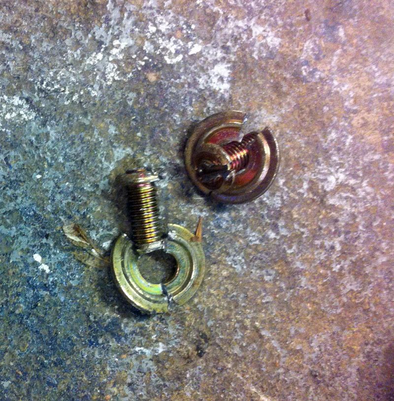
So after a lot of research, I saw too much evidence that the 6th gen (and probably every other Honda, car or motorcycle) VFR TPS is screwed onto the throttle body. It's set, "tuned", and the heads are cut off. Here's what mine looked like after I cut slots with my Dremel;
I went to the parts store with my existing TPS in hand and returned with a Dorman part meant for a 2004 Honda Pilot. Here it is installed on my bike;
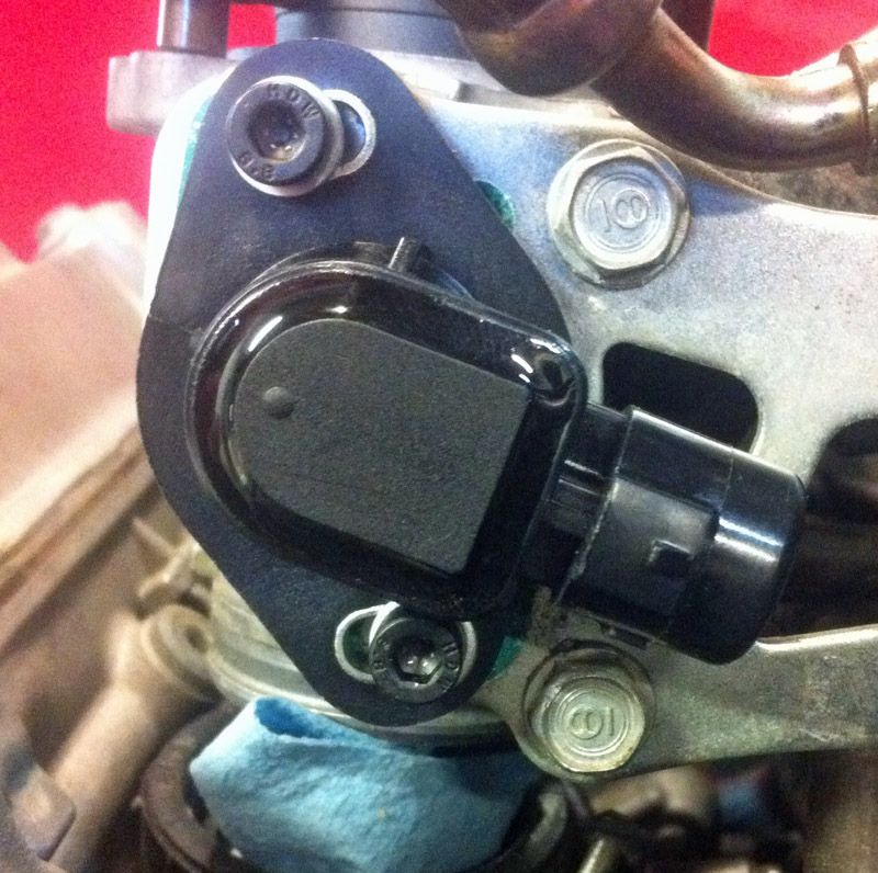
And it acts exactly like the factory unit. What I've discovered is that the TPS work perfectly by the book if I have it loose in my hand and wired to the motorcycle. This is with either the Dorman part or the original OEM part. I also still get 8 flashes of the FI light, but right now the fuel tank is off of the bike in a safe spot, so perhaps that has impact here. I don't know. The PAIR valve is also not installed but reading on vfrdiscussion.com says that this shouldn't drive a flashing FI light. I've also not cleared the ECU memory but the battery was disconnected for the last month plus so I'd think the codes would be cleared by now.
In any case, what I did discover from all of this is that I have to slightly rotate the shaft of the TPS to install it properly on the throttle body. I can almost adjust the TPS to get a proper throttle-closed voltage reading at the ECU. Almost. If I slotted the holes on the TPS (and I'd do that on the Dorman, not the OEM unit) I may be able to get there. But why has this happened?
I took the throttle stop bolt loose on the opposite side of the main shaft, where the cables attach, to make sure that the butterflies were not being impeded from rotating completely shut. This did not fix the situation and the butterflies are closing properly. It's like the tab on the TPS side of the main throttle body shaft is rotated slightly clockwise as seen by the TPS. This is what would be holding the TPS off of its closed stop and why I'm seeing about 2.5VDC at the ECU connectors when I should be seeing 5.0.
So I tried twisting the TPS interface tab around on the throttle body shaft and it seems very well attached to the shaft. No budging it with my bare hands and I wasn't about to put pliers to it.
So to sum up; the TPS sensor itself from the factory seems to be working just fine when I hold it off of the throttle body and attach it electrically to the bike. The TPS interface tab seems to be twisted on the throttle body because of this but it seems solidly attached to the throttle body and doesn't look to be mistreated. 2004 VFR's seem to use the same throttle position sensor as 2004 Honda Pilots and probably some other vehicles. I've got a blinking FI light that may or may not be important.
I wish I had access to a known good throttle body, with or without the TPS sensor. I'm not sure what to do next. Input?
-
At this point, I assume that if I'm talking about a 6th gen VFR in any way at all, I assume the stator is dying at best. At worst it's completely charred and looks like someone hit it with a blow torch. Doesn't matter if the bike is running, parked, in a ditch, or in a museum. Either have that one re-wound or replace it with new.
-
Switchblade: Is the 2014+ R/R interchangeable with the 6th gen R/R? Is it really "processor controlled" or is it just more intelligently designed?
I don't pay enough attention to this forum to know if this was really investigated or not. I definitely feel like the stators in 6th gen VFR's lead a harder life than they should and this might be a good way to improve on the situation.
-
'03 seems best of your listed trio.
-
If you got the VFRness with an integrated switched relay/fuse block, attach the meter to a switched output of the fuse block. The voltage should be very close to that of the battery in reference to chassis ground. This will also stop the meter from being a continuous drain on the battery (like the tag light offers). My volt meter on the bike is within .05V of multiple multimeters that I've used to check the battery with this configuration.
-
Cogswell: In another example of just how much Honda loves us, the TPS is held in with screws, but at the time of manufacturing the heads are cut off after the TPS is installed. If you look closely you can see that the TPS is held in this way as there are threads existing the back side of the mounting area. You have to rotate them out using tools like a punch and hammer to rotate the screws out until you can grip them with pliers or similar methods.
JT3L is the majority family markings on the TPS on my bike. JT2's are older, JT4's seem to be newer. The next set of numbers, 31105, identifies the exact TPS on my bike. In the Wrist Twisters thread on swapping the TPS off of the Honda 919, it turns out that the TPS meant for late-80's Civics and similar will work interchangeably. The biggest issue is the direction of rotation of the TPS wiper and it matches or not as they can rotate either direction.
I'm about to leave for a short vacation so I can't work on this now. I intend to pick this up on Tuesday. In researching Honda TPS issues I have found complaints of the exact failure to operate that my bike is expressing; 2.5-ish volts out of the TPS with the throttle closed. So this information may come in handy as these bikes age.
-
Okay, did some more testing this evening. Here we go, with the key on / run switch on, and measuring at the connectors at the ECU;
Lt. Green/Yellow to Red/Yellow wires - 2.72V w/closed throttle, 4.63 w/open throttle. 4780 ohms w/closed throttle, 1340 ohms w/open throttle.
Green/Orange to Red/Yellow wires - 5.01V w/closed and open throttle, 420 ohms w/closed throttle, 687 ohms w/open throttle.
Lt. Green/Yellow to Green/Orange wires - 2.28V w/closed throttle, 0.38V w/open throttle, 4750 ohms w/closed throttle, 750 ohms w/open throttle.
I believe this narrows down the TPS as the culprit. As for the TPS itself, it's marked as a "JT3L 31105". Vehicles using a JT3L seem limited; the Honda Passport from 2003 to 2005 seems to use a similar unit but I don't know if the direction of rotation is the same or not. I'm really not impressed by how Honda makes these units harder than they should be to replace. Anyone replaced a TPS on their VFR800?
-
You are correct in your assumptions about what each wire does. Green/Orange is Ground, Red/Yellow is 5V into the TPS. Light Green is the wire that varies voltage as you open and close the throttle.
Solid, thanks. So it would seem like the TPS itself is not acting in a good way when I have these screwball voltages.
When I get home tonight I'll backprobe the connector at the TPS itself and, with the ECU plugged in and the key on, check the Lt. Green/Yellow to Red/Yellow voltage potential through the full movement of the throttle. Unless something very odd is happening, I believe the readings will match what I saw at the ECU connectors last night, with 2.3V with the throttle closed. I'll also check the resistance through the switch both as a total resistance as well as from the sensor to gnd through the opening range.
If anyone else has things I should check or suggestions, let me know. Thanks for the questions and support.
-
To do a decent troubleshooting of the TPS the purpose of the three wires really should be known. I'm pretty positive that the Green/Orange wire is the ground path for the TPS. Red/Yellow is the 5V voltage reference conductor into the TPS. That means the Light Green/Yellow wire is the position derived signal from the ECU. Right?
So what's weird is how I have a touch over 5V at the VRef pin at the TPS connector when the connector is pulled, AND I have just under 5V at the signal wire. The next weird thing is that the TPS is acting like a voltage divider and not a pot; Signal wire should have something like .5VDC at that pin in reference to chassis when the connector is attached to the TPS. Not this 2.3V stuff. And then to have the voltage drop with throttle rotating open is contrary to normal TPS sensors.
Anyone have any first hand knowledge of how this circuit works on their early 6th gen VFR? Anyone have a known good TPS lying around they wouldn't mind loaning me?
-
Cogswell: One thing I find very odd is how we're supposed to do a multiplication step where the input voltage is like a variable. Why is that? If there's supposed to be a 5VDC reference voltage out of the ECU, that should be regulated, so the variability really shouldn't be in there, it should be 5 plus or minus some very small percentage. There's that same sort of math shown in Step 6 of the TPS troubleshooting pages. I can try and check the voltage potential between the Green/Orange and Red/Yellow wires at the ECU connectors to see what they act like through throttle rotation.
I'm not sure why I have these wire color differences on my 2004 vs the 2002 manual. The wiring diagram for 2006's that I have seems more accurate. I may go looking for a later manual.
-
Okay, here's what I've done so far. I took pretty comprehensive notes. This is from the 2002 VFR shop manual that's in the downloads section. I started on page 5-19, Step 1.
Step 1 - Start the bike, count the blinks: 8 blinks. No other blinks, just this 8. I inspected the connector and everything looks good and clean. At this point I put the bike on a battery charger to make sure I wouldn't have to worry about a low voltage condition at the battery causing me issues with measurements.
Step 2 - I actually did this two ways, backprobing terminals through the connector with the connector attached to the TPS, and with it disconnected per the manual. It says I should run from the Pink wire at the 3P TPS connector and ground. My bike doesn't have a pink wire here. I checked all three wires in reference to chassis ground. These were done with the key on, run switch on, bike not running.
Connected to TPS:
Lt. Green/Yellow wire to ground - 2.28VDC
Green/Orange wire to ground - 0.03VDC
Red/Yellow wire to ground - 5.04VDC
Disconnected from TPS:
Lt. Green/Yellow wire to ground - 4.92VDC (I think this indicates the TPS is good, or at least is one sign that it is good)
Green/Orange wire to ground - 0.04VDC
Red/Yellow wire to ground - 5.05VDC
Step 3 - Voltage between the AWOL Pink wire and the Green/Orange wire; there's a problem here since, again, no pink wire. So I measure voltage between the following wire pairs with the key & run switch on, bike off.
Lt. Green/Yellow to Red/Yellow - 0.00VDC
Green/Orange to Red/Yellow - 5.00VDC
Green/Orange to Lt. Green/Yellow - 4.89VDC
Step 4 - Pull the ECU connectors off the ECU and check between the Yellow/Red wire at the 3P TPS connector and chassis ground for continuity;
I checked all of them as I don't have a lot of faith in this wire color call-out. Might as well check all of them, right?
Lt. Green/Yellow to ground - No, inf. resistance
Green/Orange to ground - No, inf. resistance
Red/Yellow to ground - No, inf. resistance
The manual states that if I don't have continuity between the Yellow/Red wire at the 3P connector and ground, I have a short circuit in this wire. I think this should be "open" and not "short" but that's besides the point. Which of the three wires at this connector is the ground, really?
For fun I did this next bit where I checked for continuity between the pins at the TPS 3P connector and the ECU plugs to try and figure out where these wires go and if they rang out or not.
The Lt. Green/Yellow wire at the 3P connector rings to a pin on the black ECU connector. I would say it's in the bottom row, fourth position from the left, with the retention tab facing up.
The Green/Orange wire rings to the gray ECU connector, top row, third position from the left.
The Red/Yellow wire rings to the gray ECU connector, top row, farthest right pin.
So I made a couple assumptions at this point. Pink wire at the 3P TPS connector in the manual means light green wire on my motorcycle. I also looked the ECU connectors over; the wiring colors are the same from the TPS connector to the ECU connector. They ring through nice and clear with low resistance. None of them are pushed back or other issues. So I went ahead and did the last couple steps using T-pins at the ECU connector to backprobe the terminals.
Step 5 - Does the Pink meaning Light Green Wire ring through to the TPS Light Green Wire - Yes.
Step 6 - Check voltages from the back of the ECU with the key on, run switch on, engine off.
Lt. Green/Yellow wire on the black ECU connector to the Red/Yellow wire on the gray ECU connector, I have 2.69VDC with the throttle closed and 4.62 with the throttle pinned wide open.
Lt. Green/Yellow wire on the black connector at the ECU to the Green/Orange wire on the gray ECU. 2.31VDC close, 0.40VDC wide open.
I'm really not sure what to make of all of this. Throttle closed has the voltage pretty cleanly divided from the 5V excitation voltage from the ECU, either side of the wiper in the TPS. If the system was built that way, this TPS is working fine, and the ECU is bad. I believe the ground path is through the ECU, so pulling the connectors from the ECU and not having a path to ground is good. A path to ground would drain one side of the TPS as it operates and I don't think the system is build that way. I believe there are some mis-translations in the service manual. But how is it I'm the one finding this now?
Thoughts? If I were to take a wild guess, I have a bad ECU. But that baffles me as well. Help!?
Ecu Vs Tps: Sick 6Th Gen & I Need Some Help
in Sixth Generation VFR's
Posted
Yeah, I'm ordering a new MAP sensor today, as well as a side stand switch. The odd part is how the ECU isn't driving a single or a pair of FI blinks to signify a MAP sensor error. I'm just getting the eight. I'm going to go to other tasks on the bike while waiting for these parts to come in; chain and sprockets have been waiting on the bench for a while, maybe those are next.