
vladr
-
Posts
20 -
Joined
-
Last visited
vladr's Achievements
")


-
Understood, yeah i have seen how the second gear of the camshaft aligns itself with the first one when assembling, as stated in the manual. Based on your comment Terry from this topic [1] i understand that i dont really need to know on which TDC of the compression or exhaust the first piston (refference is) and what matters it's the sync between the front and end bank. So i'm doing right now this: 1. Put a wooden stick into the piston #3 2. Check the flywheel T3 mark with any of the TDC (360 degrees and the piston #3 will be again in a TDC, from what i understand, i will be dictating the compression or the exhaust time by aligning the camshaft as in the manual, so gear marks should be facing outwards) 3. Reassemble the cover for the rear bank 4. Turn 450 degrees and align with the #4 piston and again, marks should be facing outwards Seems pretty simple now that i've understood the principle of aligning gears but i was afraid of the "how i know which is the compression stoke TDC for reference" Let's hope it does not blow up, i will rotate various times by hand after reassable to be 100%, also i think i will also do check with the spark plug to the chassis to see if everything adds up, but for this, i will need to crank it by battery, that's where i will by most afraid. Fingers crossed and thanks again for all your help! [1]
-
So I have a new problem. Prior to removing the camshaft I’ve marked the gears with the big third one that’s on the bottom of the engine. Ive marked them in the 3 TDC for back and 4 TDC for front. After adjusting the shims and reassemble the camshafts, the marks do not correspond anymore to the position. Ive aligned the 3T mark of the flywheel and the marks that I’ve made are in another position, even tried a 360 to be sure that the TDC so not sure what I’m missing. Is it possible for them to desynchronise? I assume I should start over again and do as Mohawk suggested by inserting a rod to the spark plug to find the 1 TDC and from there sync all the gears but it does not make any sense to have them marked and then somehow not being miss aligned.
-
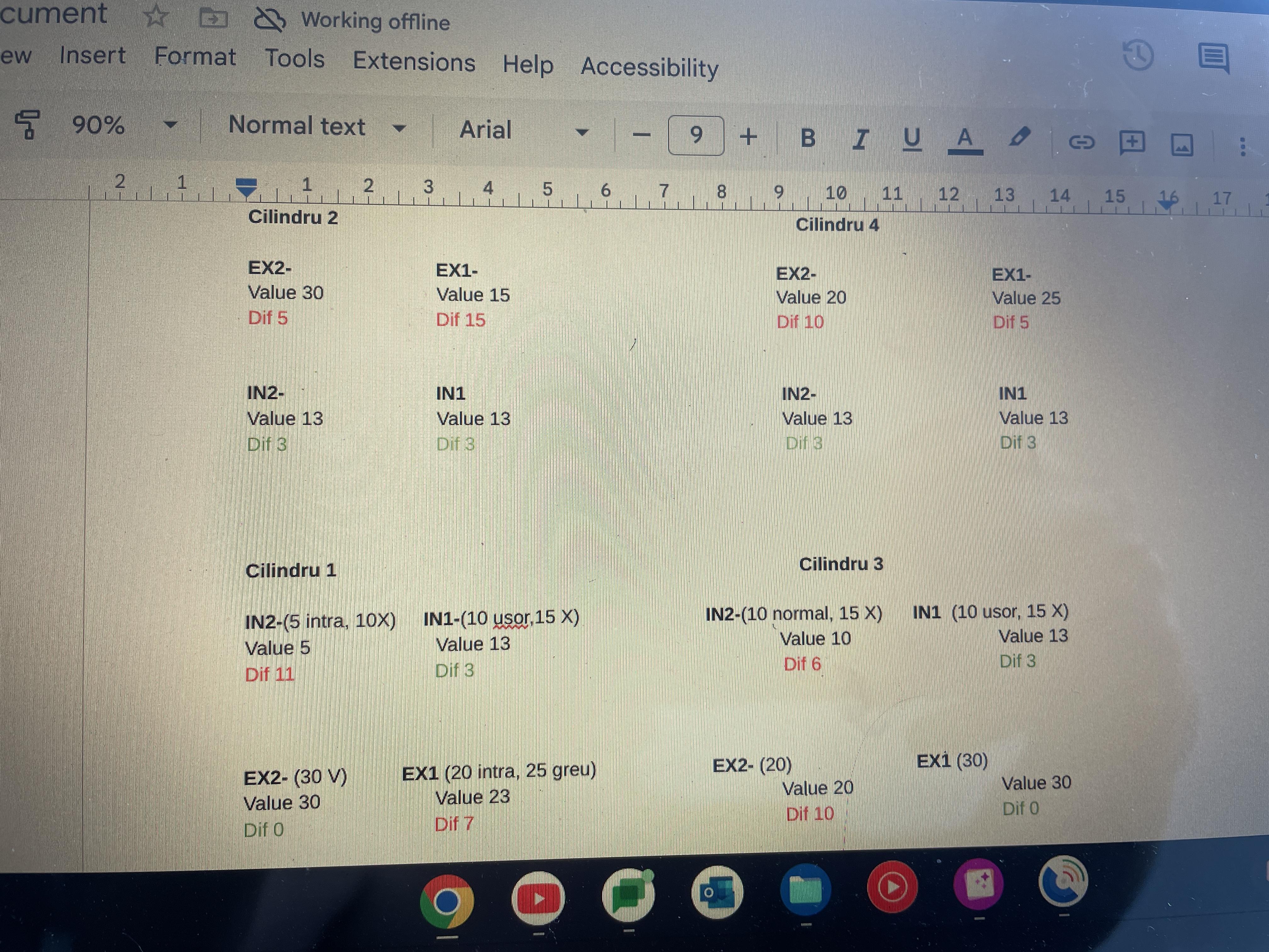
Yep, stupid me, it was not the compression stroke and somehow managed to turn the flywheel more than 360 every time that I’ve checked for it… Many thanks for the help! Regarding the clearance, here are the specs. For some reason almost all the IN valves had the same value, except two that were pretty off. And on the cyilinder 2, there’s a big gap of 0.15 for one of the EX, which confirms the theory of Grum from another topic in which the vaccum couldn t be increased to the right value in this cylinder. Most probably an open EX valve. Tomorrow I will do the math and see which shims I need. Somebody recommended to switch them up if the dimensions corresponds or even sangrinding them to the corect value. But for sure I will stick with just changing them with new shims. Thanks again!

-
I’ve started to do the valves check today, adjusted the timing marks from the flywheel on the TDC for piston 1. And when I’ve opened for the first time the rocket cover, noticed that the timing marks of the cams are 180• reversed. Totally in contradictory with the manual [1], where the left one should be pointing up and the right one down. Seen a guy on YouTub [2] which on a restoration did the same positions as I have and it didn’t crank up. So he switch it back in the same position as in the manual and every thing worked fine. So the simple questions is, how is this possible? I’ve been running like this with it from when I’ve bought it. For sure it has to be something that I’m missing. This, or indeed whoever did the valve checks before, somehow manage to desync the timing and somehow still works? Any idea would be appreciated. [1] IMG_5221.mov IMG_5221.mov [2] https://youtube.com/clip/UgkxW7Yic71hCCyUioLELMQbIfL89G2_5Fo5?si=IQwLYtu9uX63_eUm IMG_5221.mov
-
-
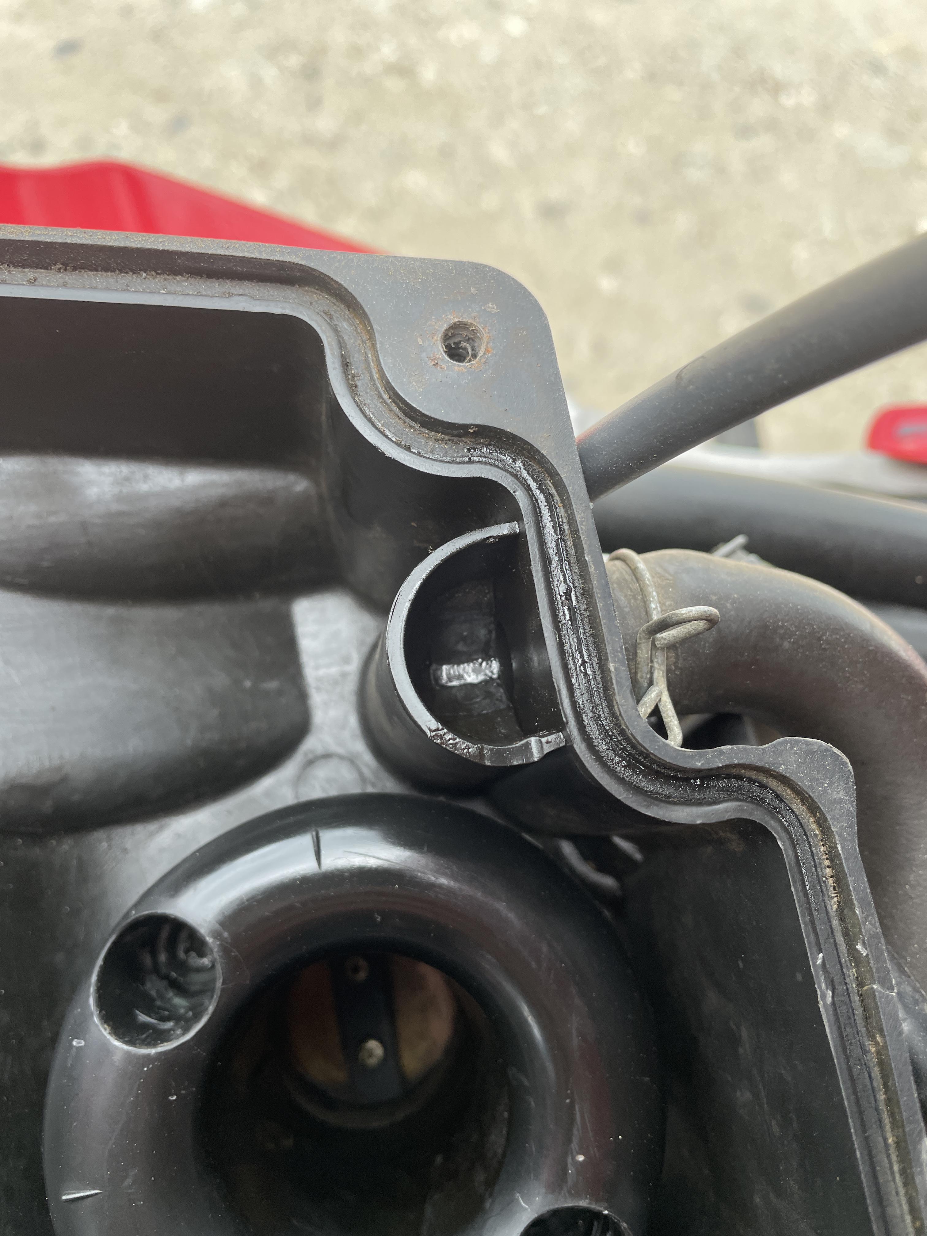
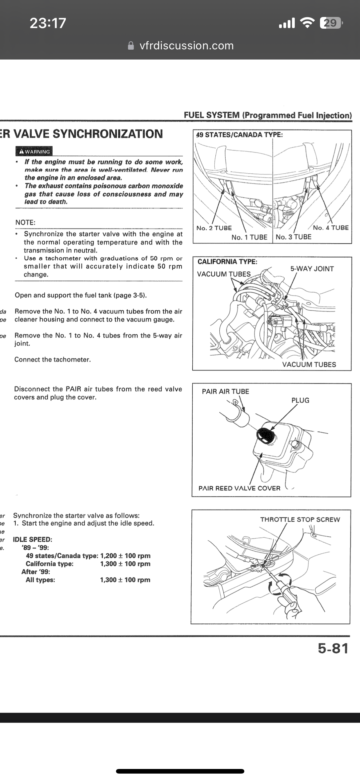
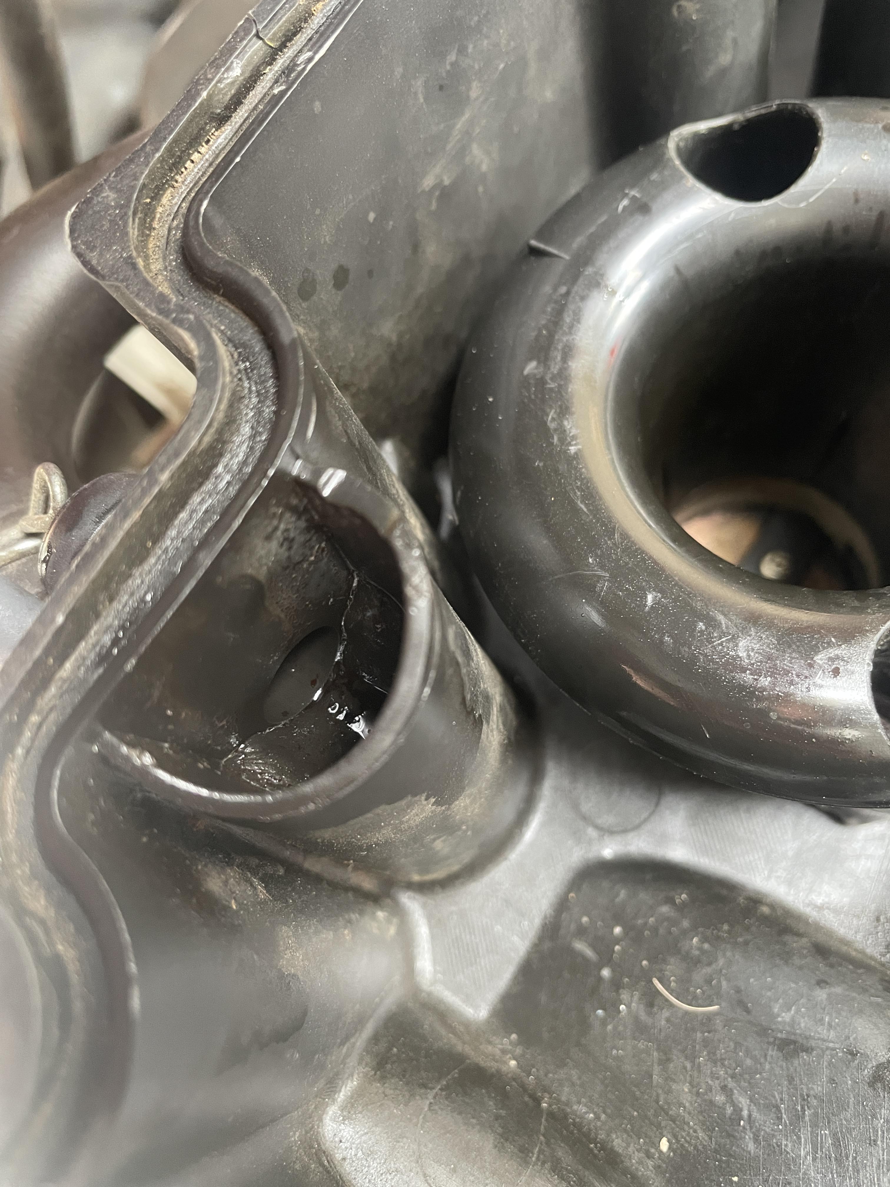
Yep, throttle bodies were cleaned according to the manual. So today I’ve decided to take another look. Removed everything except for the TB per se and made sure that everything is in place again. Sprayed aerosol all over the air box, funnels and hoses to recheck for any leak, nothing found. Double check all the connections to the harness and back, same. Still couldn’t test the compression as I will need to rent one from someone first but power output wise engine runs well. Ive tune again the vacuum to other values: #1: 2.1 cmhg #2: 1.1 cmhg (instead of max 1.6) #3: 2.3 cmhg #4: 2.2 cmhg Runs much smoother but with pops and bangs as well as fire coming out of the exhaust on deceleration. So I will revert back to the previous values. Inspected the screw mechanism for all cylinder and they seem to work properly, #2 also as I can decrease the value but not increase it. One interesting thing, it seems that from the crankshaft breather there’s unburned gas (see photo), so this makes the speculation of being a burned valve even more plausible. Will get back with a compression test and hope for the best. Thanks again Grum!
-
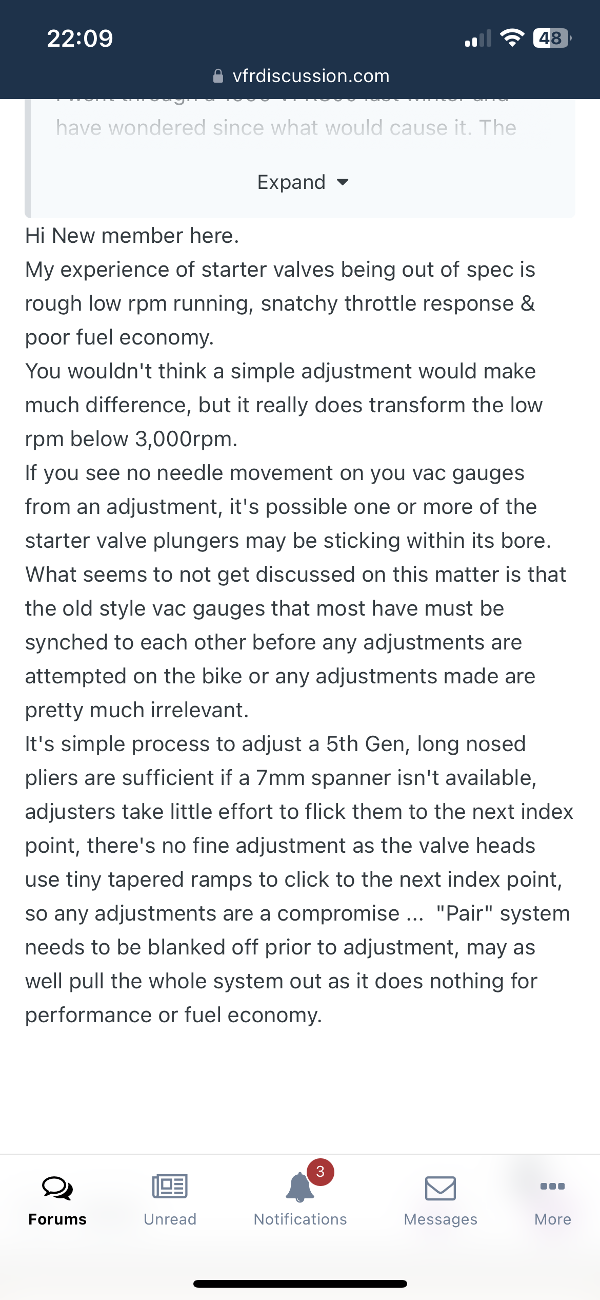
Oooor the plunger as stated here. Not sure how I should verify them without taking the whole throttle body apart. Probably no other option.
-
Thanks everyone for the help! Then my whole life was a lie, I thought the 4 hoses are attached to the airbox to receive air but now I realize that they are vacuum hoses... So stupid. This means that the placebo effect worked and made me think that I can sync the TB more effectively, but it was a lie the whole time... The air filter was new when I bought the VFR one year ago, made around 15K km and I've inspected and cleaned it when I got the sync valve job the first time one month ago. It looked good with only just some normal debris that were cleaned. I'm riding the VFR every day, and it seems that the jerkiness of the throttle is the same. On low acceleration, it feels like chugging and I need to open the throttle more for it to become 'normal' and resistive. So it seems that all the issue is with the first 25% of throttle. After some more asking around and reading, I come to the following hypothesis: - Valve shims worn off/clearance not in parameters > burnt valves > cannot sync throttle valve for cylinder #2 > incorrect balance of the engine fire times > power output delay > throttle jerkiness/chugging and numb vibrations of the left foot peg (where cylinder 2 is located) Could this be correct? Valve clearance should be checked at 10k and most probably the previous owner did this as the cover gasket seems new. But as Grum said, I will first start with the compression test to eliminate this possibility.
-
On contrary, Grum, many thanks for all the help offered! I have the EU model with the 4 hoses separately for each airbox connection. I will go ahead right now and try blocking them off totally while doing the sync ( not letting them connected on the air box) - for the compression test I will have to way to get home - rubber body, I will check those too and see if they fit well onto the airbox - from what I’ve understood the sensors are interchangeable for 5th and 6 th gen, I’ve got a map sensor from 6th gen to the baro of my 5th one and indeed the fi light of one long blink (error code 10 disappeared) but I will try to swap them up to see for any chnages - at first glance neither of the hose were cracked or twisted and everything seems connected well, the two big tubes from underneath the throttle body, the big one from the front of the airbox and the other one from the breath tube do the cranskshaft (which from the previous photo it seems that there s oil in the passage, something I didn’t recall being there on the first check), the flapper valve and the map sensor. - I’ve got a beeter understanding now thanks to the technical section from the manual I will go ahead and check the remaining things, also I will try to block the flapper valve vacuum hose for any change and I will keep you updated. Thanks again grum for everything ! UPDATE 2: After syncing the throttle valves again, but this time blocking the other hoses, the engine has power, but the temperature exceeds 100°C at speeds over 80 km/h, even with an ambient temperature of 20°C. Clearly, this was not the case before, as I'm aware that the VFR runs hot, but it never reached 107°C while riding, not even last summer when it was 40°C. So now, I'm assuming that because it's the only cylinder not calibrated, it runs rich, and thus, this issue arises. I'm really considering the burned valves that you told me about. I'm still unable to perform the compression test, but I will proceed with it in the coming days. So, it could be a burned valve, or the screw mechanism for that cylinder has failed, or any other issue you've mentioned above.
-
Another updated: After disconnecting everything and cleaning the TPS sensor with contact cleaner, it seems that the FI light is no longer on. I've tested it for the past 3 days, covering more than 500 km on a country trip. So, no more errors have been stored after this. I will keep an eye on this topic, but now I would like to focus on the valve sync for the following reason: I tried again to sync the throttle bodies as stated step by step in the service manual, including the pair valve, etc. (One question: the manual states to disconnect hose 1 to 4, meaning that the other 3 hoses should be disconnected from the airbox while I do the sync? I'm asking this because I only have one vacuum gauge. I don't think, and until now, I've been doing it with them connected.) After following your recommendation and after 200 km, the sensation was that everything flowed much better. I was finally able to change gears without that small jerky motion that I've never got the hang of. Everything seemed decent, but I could feel that the power output was much lower, and I had to go full throttle for overtaking other cars. So, smoother but less power. Also, no more running rich and no pops on deceleration. I decided to redo everything as it didn't quite feel perfect (my mistake), and I've got the following new values: - Cylinder #1: 2.0 cmHg - Cylinder #2: 1.0 cmHg - Cylinder #3: 2.2 cmHg - Cylinder #4: 2.1 cmHg After trying various times to get the same values and feeling as before, nothing helped. Now, I have much more power again, but everything is very jerky, and I feel that the response of the acceleration has a slight delay until the action has to be done by the engine, thus jerky when changing gears. So, I'm running out of ideas. I cleaned all the SVs and verified they open synchronously. The flapper valve is still connected and theoretically working. Should I try closing the vacuum hose and test it like that? So, what else could be the culprit in this case, only happening to the 2nd cylinder? Could the TPS sensor have anything to do with this? Is it worth changing the baro sensor (which is from a 6th gen) with the MAP one, maybe it's related?
-
I’ve come back with some responses: 1. Voltage Checks: - Verified that the **TPS**, **Baro**, and **MAP sensors** have a **5V Vcc voltage** on the Pink wire, so voltage is consistent across these sensors. - Confirmed that the TPS has a **Signal Ground** through the ECM on the Green/Orange wire, and checked that all ECM Grounds (B1 Green wire, A9, and A20 Green/Pink wires) have good continuity back to the Battery Negative terminal. 2. Continuity Tests: - Checked the continuity of the **Light Green wire** (TPS Signal to ECM) and found no continuity with the negative terminal. - Neither the Orange/Green nor the Green wires had continuity with the negative or chassis, not sure if this is normal or not. 3. Grounding and Resistance: - All three wires (B1, A9, A20) have continuity with the battery's negative pole. - The Green/Orange wire has good continuity with B2. - The TPS signal to ECM wire (Light Green) has good continuity with B14. - The Pink, Green, and Green/Orange wires have good continuity to the ECM. 4. Sensor Resistance: - Attempted to verify the resistance in the TPS sensor but couldn't read any values, possible faulty TPS? - Similarly, couldn't measure any values for the MAP sensor resistance, which may indicate an issue with the voltmeter or the sensor itself. Is this normal or I’m missing something? 5. Throttle Valve Synchronization Issue: - Initially, cylinder number 2 could not be synchronized, as adjusting the screw only decreased the vacuum without improvement. - After attempting to synchronize the throttle valves as you’ve recommended, the same issue occurred with cylinders 3 and 4, unable to achieve a vacuum higher than 2.1 cmHg, which is the same as the reference cylinder 1. So I’m thinking of any possible leak
-
Many thanks, Grum. When I wrote the post, I knew you would be the only one to respond. You're still active on this forum, so many thanks for your service! 1. I know that the service manual states there should be 20 mmHg more, but based on this forum [1], it seems there should be less due to an incorrect choice of words in the manual. Nonetheless, I will also try, as you've stated, by adding more, but the issue with the 2nd cylinder still persists, so I don't know how I should be able to provide a higher value. My values at the moment are: - **#1**: 2.2 cmHg - **#2**: 1.8 cmHg - **#3**: 2.0 cmHg - **#4**: 2.1 cmHg After doing this setup, the vibrations after 6k rpm could be felt only on the left footpeg instead of the whole motorcycle (before doing any adjustment), so it's an improvement. I'm assuming the 2nd cylinder being off is what gives those vibrations on the footpeg. I will try as you've suggested and get back to you. 2. I will go ahead and follow your recommendations regarding the wires and voltages for all three sensors. Thanks again; those are indeed helpful pieces of information. 3. The spark plugs have been changed to iridium ones when doing the valve sync, and there was an amazing difference. The acceleration was much quicker, but I still feel hesitation, most likely due to the TP sensor. I didn't check the fuel filter, so I will do that. Water or bad fuel could be an issue, as after refilling with fresh fuel, the hesitation was less prominent. Also, what I've observed is that if I have a temperature of 80°C, the hesitation does not happen that often. If I go into the city with a temperature of 100°C, then it happens more frequently. 4. A burned valve is exactly what I don't want to hear. I will go ahead and do a compression test, but somehow my intuition says that the engine compression is healthy and that this should be related to either the mechanism screw or a vacuum leak (if it's possible). Thanks again, Grum, for everything (I owe you a beer)! [1]
-
Hello all VfR 800 1999 5th gen For the past weeks I’ve delved into fixing all the small and complex issues from my vfr, but it seems that I’m completely stuck with some topic in particular. Chronological Order of Events: 1. Initial Symptom: - The engine began to exhibit hesitation and jerky movements while maintaining a steady throttle position. 2. Diagnostic Code: - I’ve got a long blink indicating an error code 10, pointing to an issue with the barometric sensor. 3. Sensor Replacement: - After conducting some tests, I’ve bought a barometric sensor from a 6th generation model and installed it. 4. Resolution of Error Code: - The replacement of the sensor eliminated the error code, and normal operation seemed to resume, so I’ve continued with the repairs. 5. Throttle Valve Synchronization: - During the synchronization of the throttle valves/starter valves, I’ve encountered an issue with cylinder number 2. Detailed Issues and Questions: 1. Cylinder 2 Synchronization Issue: - Cylinder number 2 could not be synchronized; adjusting the screw only decreased the vacuum, and completely unscrewing it did not increase the vacuum beyond 1.8 cmHg. - Question: Could the mechanism be broken, or is there another issue I'm overlooking? Is it possible for a vacuum leak to affect only one cylinder's adjustment, despite all four cylinders sharing the same intake from the airbox? The hose from cylinder #2 does not appear to be cracked. 2. Power Delivery Delay: - After reassembling and testing the bike, a delay in power delivery was experienced during rapid and forceful acceleration, nearly causing a loss of control. - Subsequent testing revealed an error code 8, indicating a potential issue with the TPS (throttle position sensor). - Question: Can a vacuum leak be related to the issues I'm experiencing, including the inability to adjust cylinder number 2 and problems with the TPS sensor? 3. TPS Grounding Concern: - Research on various forums suggested that the TPS could be grounded, although the contacts appeared to be correctly in place. - A resistance measurement between the negative pole of the battery and the engine block showed approximately 200 milliohms. - Question: Is this resistance value normal? I'm not an expert, but having resistance on the engine block itself seems unusual. Please let me know if you need further assistance or clarification on any of these points. And thanks for your help!
-
FOR FUTURE REFERENCE Amazing news, I've bought a SH dashboard and just for curiosity measured the R1 resistance. Strangely, it's a 30 Ohm. Hope this helps for others that pass through the same issue. Soldering one should be the cheapest way to have a working dashboard again. Regarding your question Grum, I agree with you but my main issue was that the br/bl wire had an abnormal ground that somehow sent it over the w/bl, br/bu and r/bl wires though the fuse box C from the diagram scheme. I've discovered this with a multimeter and checking the fuses with the ground. From all 6 fuses (excluding the clock one) 3 of them had w ground. If I ve unplugged the fuse C, the other 2 D and G (or F don't remember for sure) worked fine without a ground on them. Thus, unplugged all the fuses and checked directly the wires that go from them. And the culipt one was the br/bl. The chronological order for he issue was: While riding with 18v, dashboard showed 0 and after 10 second engine died. Battery exploded and smoke was coming from the ECM Saw the Maine fuse A blowed so I was thinking this should be an easy fix. Started to blow everytime Ive turned the ignition on. While testing this and burned over 10 fuses, the ECM started to smoke with the ingition on from the Black wire, this is the point from which something changed in the circuit and the issue with the 3 fuses connected in series started to appear. I assume that the ECM had a ground in the black wire and from then goes to the relay fuel pump and ground the br/bl ones and the respective one ground the other 2 fuses until half of the circuit it's grounded. This explains why the fuel pump was not priming and why the fuse blows. In either way, this issue seems to be solved as it was a 30ohm one. The bogging one I still think it's something relatively normal as this happens only when the engine is cold, no test to deduct a theory should be performed on a cold engine. I will further test for the over 6RPM issue, that one really has the possibilty to truly be an issue. Many many thanks again Grum for everything, we need more people like you!
-
VID_20230723_174653300.mp4