


GreginDenver
-
Posts
307 -
Joined
-
Last visited
-
Days Won
7
Content Type
Forums
Profiles
Gallery
Blogs
Downloads
Events
Posts posted by GreginDenver
-
-
1 hour ago, sfdownhill said:
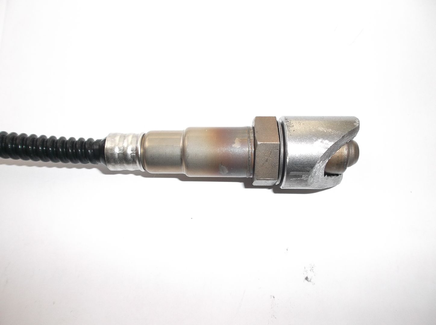
Jozef measured the Bosch wide band sensors he uses with the Attack dyno for tuning and came up with 27mm from the base/seat of the sensor’s threads to the sensing tip. This would be the same measurement as from the top of the bung to the sensor’s tip when installed. If anyone has a different measurement for the Bosch 4.9, please let me know.
27mm sounds like an accurate measurement of the sensor's tip-to-seat distance (1.063 inches),
The pictures I posted (above, in this thread) are of a Bosch 4.9 (5-wire, heated) O2 sensor being installed into an Innovate Motorsports Extended O2 Sensor Bung which has a 1 inch total length, and in one of those pictures you can see how far the tip of the O2 sensor protrudes beyond the bung.
In the top picture the extended bung has already been heavily contoured to fit tightly against the exhaust's mid-pipe section, but the upper-right hand end of the bung is still very close to the original total length.
Sorry that the best picture I have (the top pic of the 3 that I posted) is a slightly angled viewpoint of the assembly and that this picture was taken when I was already well into the process of contouring the end of the bung so that it would closely mate to the outside of the exhaust's mid-pipe, but at least you can see well enough to get a good comparison of the lengths of the bung and the sensor tip.
-
 1
1
-
-
4 hours ago, Mohawk said:
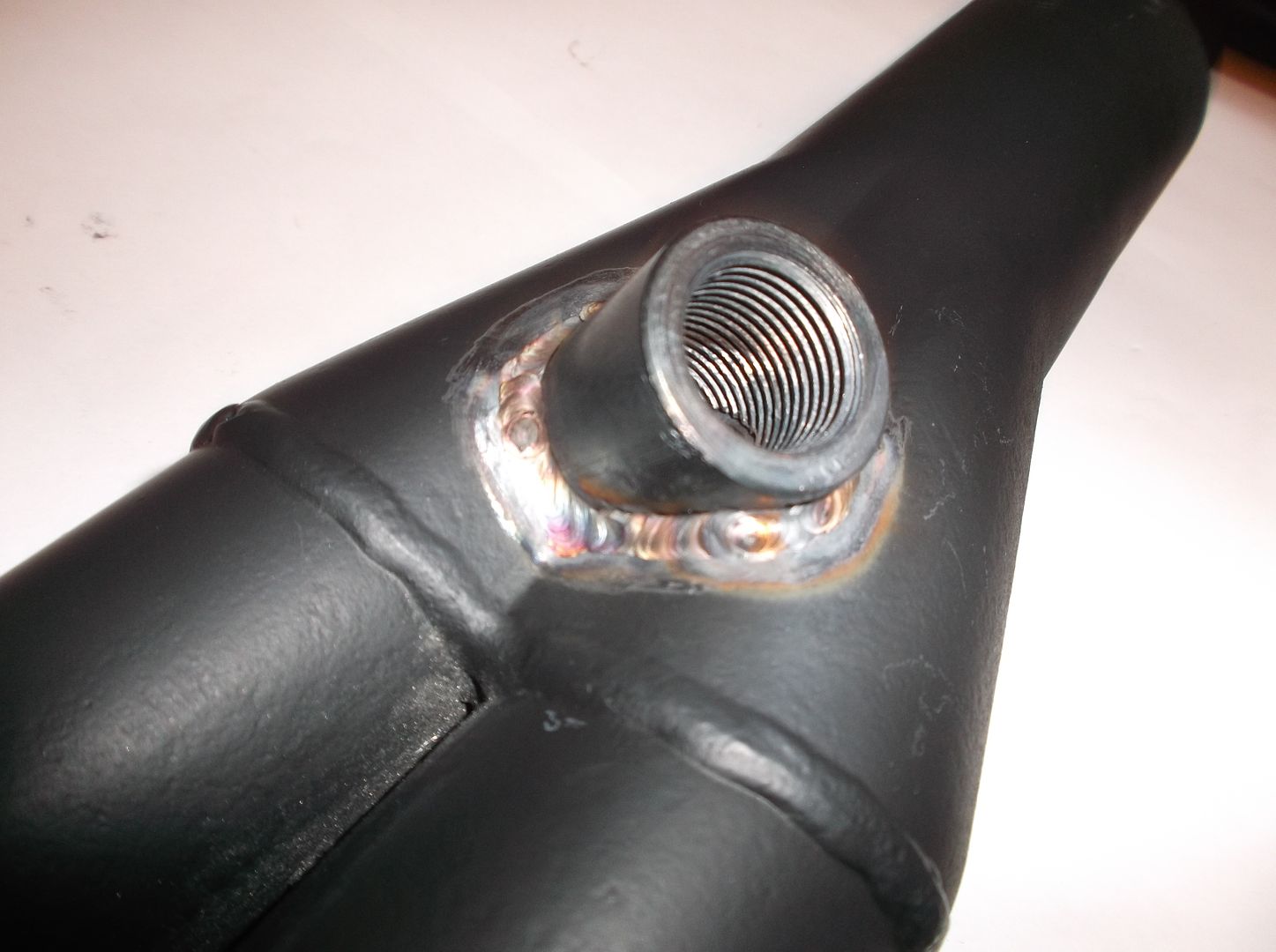
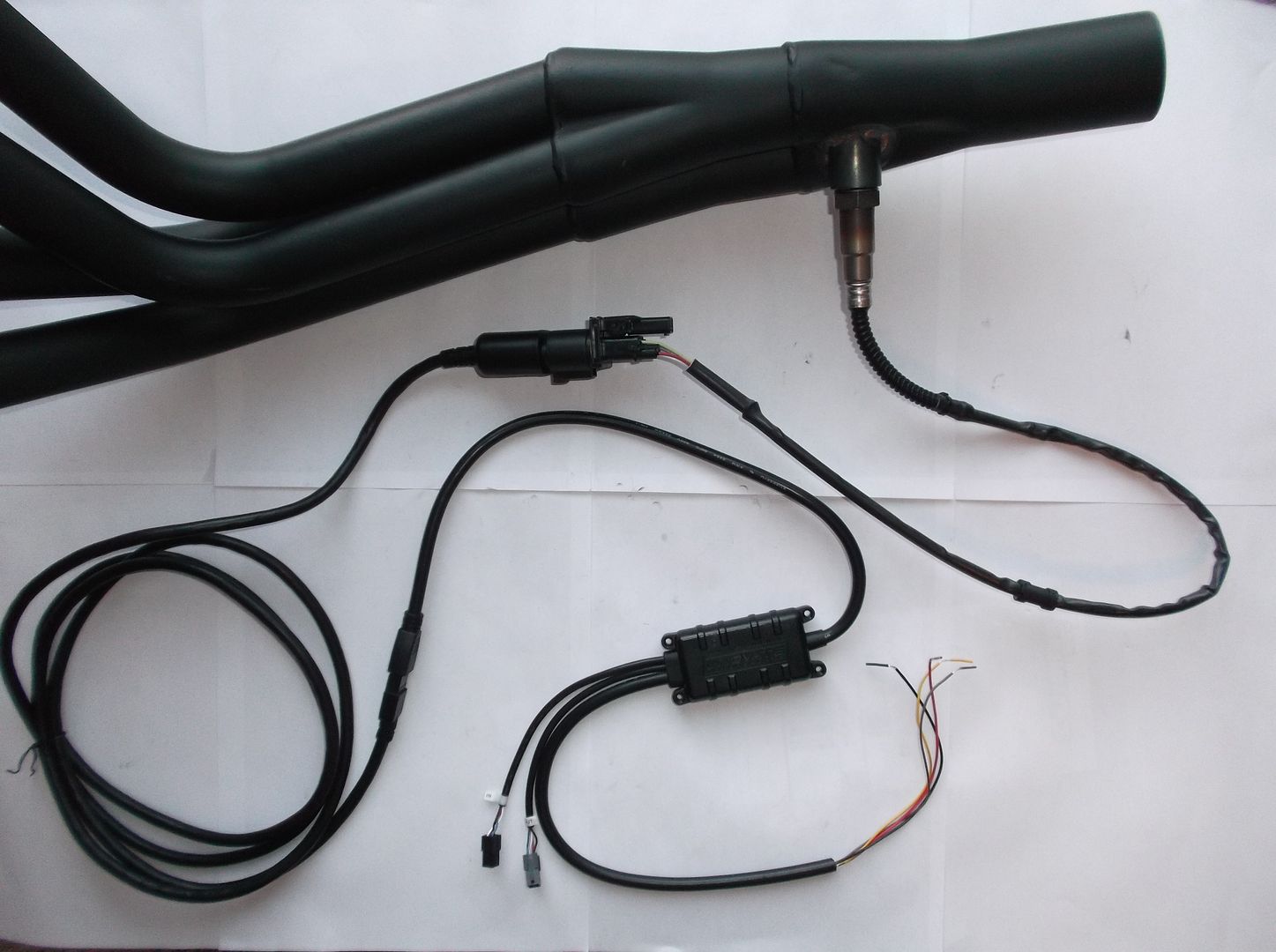
Recessing them from the header, so that the sensor tip is flush with the ID of the pipe, actually creates an eddy zone that should in theory make their reading more average, but they are best placed with just the triangular tip section protruding inside the ID of the pipe, being offset to one side they will not cause a full reflective pulse & should not hinder gas flow.
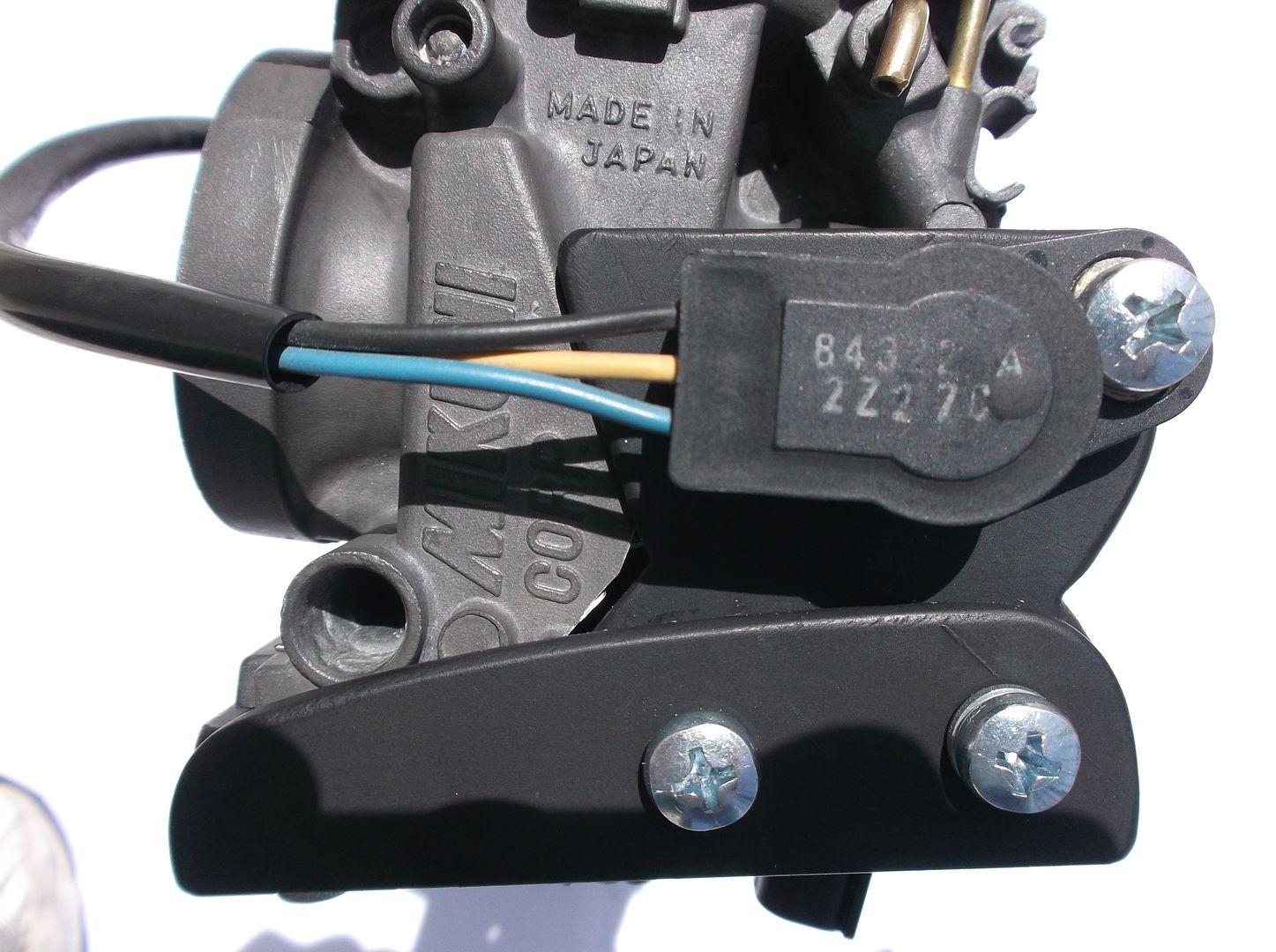
I've been working on do-it-yourself motorcycle fuel injection projects for about 10 years now and the above post pretty much describes how I mount my Wideband O2 sensors. I always use an "extended length" O2 sensor bung. You can see in these build-up pictures how far the O2 sensor protrudes beyond the end of the bung (when you visualize how far it will protrude into the exhaust remember to include the wall-thickness of the exhaust header itself) . This amount of protrusion (or even a little less) allows the sensor to work properly.
-
10 minutes ago, SEBSPEED said:
Bottom line, the bike will run, but it would be to your advantage to add a tuning device. You don't have to tune it for "ultimate powah" if you don't want to. You could instead tune it for efficiency if that were your preference.
Guess I'll have to start reading up on the various boxes available for the 5th Gen, unless you're going to tell me that there's a clear winner in the group, an obvious choice that everyone agrees is the way to go.
-
Hope this isn't a dumb question, here goes: It seems to be assumed that every VFR getting one of these exhaust systems will also have some sort of tuning box/device. I haven't gotten into tuning either of my 5th Gen VFRs, is it a necessity with this exhaust?
I was just going to buy the exhaust as a replacement for the ugly, rusted OEM exhaust that's on my '99 without any thought about tuning the bike for more horsepower.
Am I thinking wrongly about this thing?
-
1
-
-
9 hours ago, Lee 2002 said:
RC51 - have a very similar flapper in their air box. It is interesting to note that I never saw a race-prepped RC51 with an active flapper (including Honda supported teams). However street-going RC51's sold by Mother Honda that were subject to EPA regulations did come with an active flapper.
I'm wondering if "race-prepped" motorcycles are the best source of modification ideas/guidance for people who ride motorcycles on streets.
-
2
-
-
11 hours ago, boOZZIE said:
If you have a look at Honda's own parts fiche for 2017 8g vfr800 with the same airbox you will note not that they DO NOT supply the variable intake valve anymore and have replaced it with a cap, ie deleted it. Now I do not own a new 2017+ 8g so I'm not sure if they even have the valve anymore.
Credits to Grum for doing a thread on this several months ago
If one engine has VTEC and the other does not do you think these two engines might need a different airbox configuration?
-
2
-
-
I heard that the EPA fired their motorcycle intake noise regulation from the "grassy knoll".
-
 1
1
-
-
46 minutes ago, FJ12Ryder said:
I've been around motorcycles for many years and watched the industry struggle with noise control issues. Very few companies
allow unrestricted intakes due to noise issues, same with exhaust systems. The VFR is a noisy motorcycle due, in part, to it's
gear driven cams. I figure the restrictive intake is one of their efforts to lessen the overall engine noise. JMO of course. But I
also think Honda put a positive spin on it, just because that's what they do. Have lemons? Make lemonade. Have to restrict air
intake for noise purpose? Make it sound like you're doing it for a reason other than that.
It sounds like you're just gonna double, triple and quadruple down on your "noisy intake" idea. And not only that, you're gonna go all conspiracy theory (Honda doesn't want us to know this stuff... black-helicopters, chem-trails).
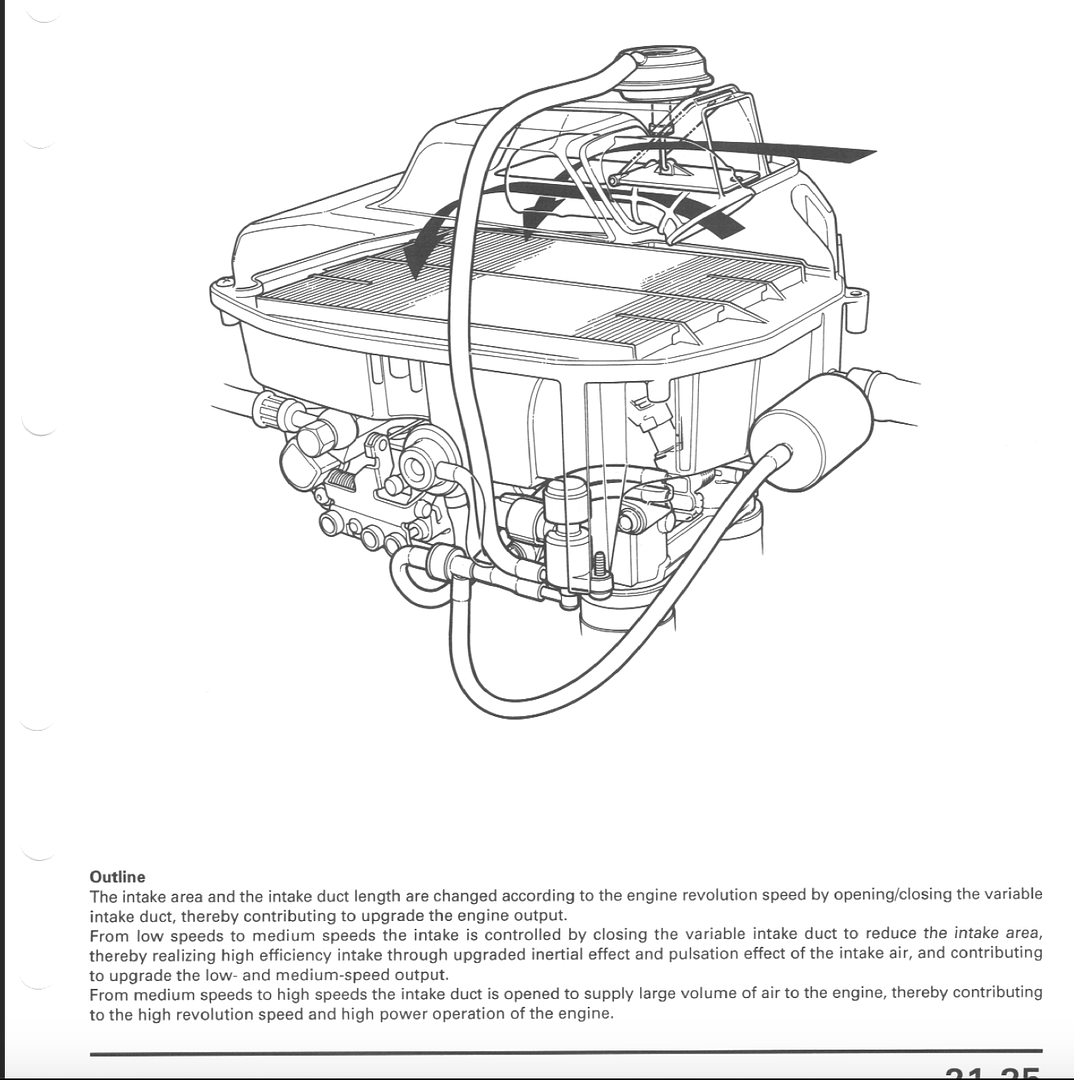
And you're doing this in spite of the fact that Honda very plainly explains (in Chapter 21) that the VFR800 airbox is not restrictive at all. I mean look, read, understand... here it is in plain black and white:
-
Okay, let's talk/debate...
Maybe, before we start talking actual technical issues, we should try to work out a couple of what I'm seeing as "barriers to communication".
First, you seem to be very strongly self-convinced that the VFR's airbox was designed the way it is for noise abatement reasons. I find this to be very strange, I've read a a lot of the published literature on the VFR and have never seen any mention of this, where in the world did you get this idea from?
Second, it seems that you want to discount the information in the Service Manual Chapter 21. Why do you think Honda went to the trouble of including the Chapter 21 information? Can you give me a good reason why I shouldn't take Chapter 21 at face value?
-
15 hours ago, FJ12Ryder said:
Yeah, that's about it. Removing the flapper valve and snorkel, which is what several of the modifications basically
consist of, gets rid of any obstructions to air flow into the airbox. With fewer obstructions to the airflow into the
airbox, you could get more air flowing at higher rpm's, possibly resulting in more power at higher rpm's.
IMO regardless of the verbiage in the HSM, Honda did the snorkel and flapper valve to help lessen intake noise, and
touted it as a "good thing" for power. Maybe, maybe not.
Personally I don't think it makes much difference either way...which of course is why I've never messed with it.
You're not getting me (can't tell if you're doing it on purpose or by accident), but let me be clear: I'm completely disagreeing with you on this subject.
Once again, reading Chapter 21 of the Service Manual will completely debunk everything you (seem to) believe about Flapper Valve and Snorkel modifications.
I'm totally willing to discuss this situation in depth, issue-by-issue, if you would like.
-
3 hours ago, FJ12Ryder said:
To me it's similar to putting a free flowing intake on an engine: you lose some low end, but gain it back, and then some more, at the top end. It's pretty
much a non-issue IMO.
Okay, just in case I'm missing something here:
You're saying that performing a mod to make the flapper valve stay open during low Rpm/low "demand" situations (instead of closing as it was designed to do) somehow delivers more horsepower in the higher RPM/high "demand" conditions (during which the flapper was always programmed to be open anyway)?
I'm confused.
-
1
-
-
By the way, doing "the usual snorkel-flapper mods" isn't really a great idea.
Yeah, there's a lot of back-and-forth argument on this subject but I can tell you that 99% of the guys (maybe even 100%) who argue in favor of this modification have not read Chapter 21 of the 1998-2001 Honda VFR800FI Interceptor Service Manual, which is entitled, "Technical Features".
If you were to carefully read (and understand) the information Honda has provided in this chapter you would realize that disabling the flapper valve and messing with the snorkel is a counterproductive effort. I'm not going to try and explain the whole situation here in this post to your forum thread, but the most important piece of information contained within Chapter 21 is that the VFR800 ECU runs in two different modes, depending on "demand" (which is closely, but not completely, related to throttle position). In conditions of low demand the ECU makes its fueling decisions primarily based on information provided by the Manifold Absolute Pressure Sensor, and in conditions of high demand the ECU makes its fueling decisions primarily based on information provided by the Throttle Position Sensor.
Now I'll leave it to you to carefully read and understand the Chapter 21 information and by doing so come to an understanding of why the snorkel and flapper are installed on the engine (and why the Honda engineers programmed the flapper to open and close when it does).
-
2
-
 1
1
-
-
Here's a bit of information that hasn't been mentioned yet in this thread: the 5th Generation VFRs breath pretty heavily through their crankase ventilation system, which dumps the oily blowby gases into the bike's airbox. As a result of this the intake valves can end up with a good bit of carbon build-up on them. If you're going to take off the throttle body, for something like getting at and replacing the thermostat or to remove the injectors to send out for cleaning, you should look at the intake valves to see just how much carbon is stuck on them.
Both of my two 5th Gen VFRs are low-mileage but both of them have a good bit of carbon build-up on the intake valves. I'm currently looking into various ways of cleaning them up.
Another possible cause of fueling problems is a fuel pressure regulator that is beginning to fail.
-
2
-
-
11 minutes ago, BiKenG said:
I see, so there's a MAP sensor for each cylinder. I have a funny feeling Honda MAP sensors are rather expensive, but I guess he's using a more cost effective sensor.
Motorola MPX4115 MAP sensors are pretty cheap. I always use the MPX4115 because it is their basic atmosphere model (as opposed to other MAP units designed to handle turbo or supercharger boosted engine MAP signals), they sense in a range from 115 kPa down to around 9 kPa.
-
1 minute ago, BiKenG said:
I see, so there's a MAP sensor for each cylinder. I have a funny feeling Honda MAP sensors are rather expensive, but I guess he's using a more cost effective sensor.
All food for thought re the CBX, but is another reason for grafting the 800s injection onto the 750 as provided it can physically be done, then it's relatively simple as there's a ready made wiring harness with all the required sensors and just the one ECU module. No other ancillary electronics required. Well, apart from a Power Commander or equivalent. At least I assume it will need some tweaking, although just have to see on that once it's running.
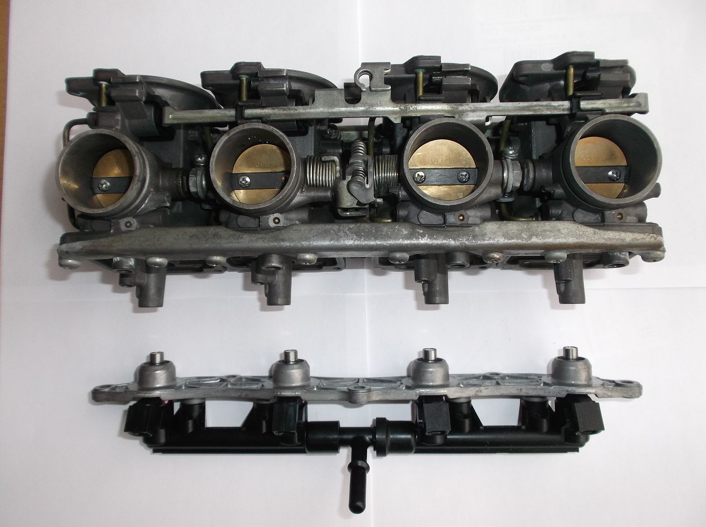
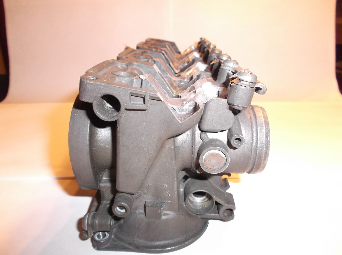
Did you go to Patrik's NC30 Fuel Injection project blog (as was suggested on page 1 of this thread)? If "simplification" is your overall aim it's important to realize there are different areas of a motorcycle fuel injection project that can present as very, very complex. If you take the time to read Patrik's NC30 blog you'll see how complex it was for him to adapt throttle bodies to the bike. He has skills and equipment that I will never have (CNC machining, for one example, and he's highly mathematical).
So I choose to simplify by not attacking areas like the mechanical aspects of the throttle body (especially a throttle body assembly as complex as a Honda V4!), and instead I'm willing to suck up the punishment of lots and lots and lots of wiring and soldering.
-
7 hours ago, BiKenG said:
How does the MS use MAP sensor output to detect engine position? If the MAP sensor is connected to all intakes, how does it know which pulse is for which cylinder?
BTW, why did you choose the MS over say Motec?.
The Firmware load that the MegaSquirt and MicroSquirt use is Open Source, so guys are free to be creative.
Your question about the MAP sensor is a perfect example: One of the problems with fuel injecting motorcycle engines is that they are always configured with Individual Throttle Body arrays (both carbs and throttle bodies count). Individual Throttle Bodies are great for high-revving performance applications (most motorcycles) but they produce a very poor and messy vacuum signal to a MAP sensor. So running a single MAP sensor is always a bit of a problem. A guy in Germany has developed a build-it-yourself, advanced Multiple-MAP-sensor unit that uses an Arduino Nano to monitor four MAP sensors (one for each cylinder on his ZX-7R). The code loaded into the Arduino Nano looks at all four MAP sensor signals and determines which is pulling the most vacuum at any given microsecond. Then the Nano forwards that signal to a Digital-to-Analog converter which is wired into the MicroSquirt's main MAP sensor input. Also, the Nano knows which of the four MAP sensors is connected to cylinder #1, so whenever it sees that particular MAP sensor pull its highest vacuum it (the Nano) generates another digital output that mimics a camshaft position sensor (again out of the Nano as a digital signal, then through a DAC and on to the input on the MicroSquirt for camshaft position).
-
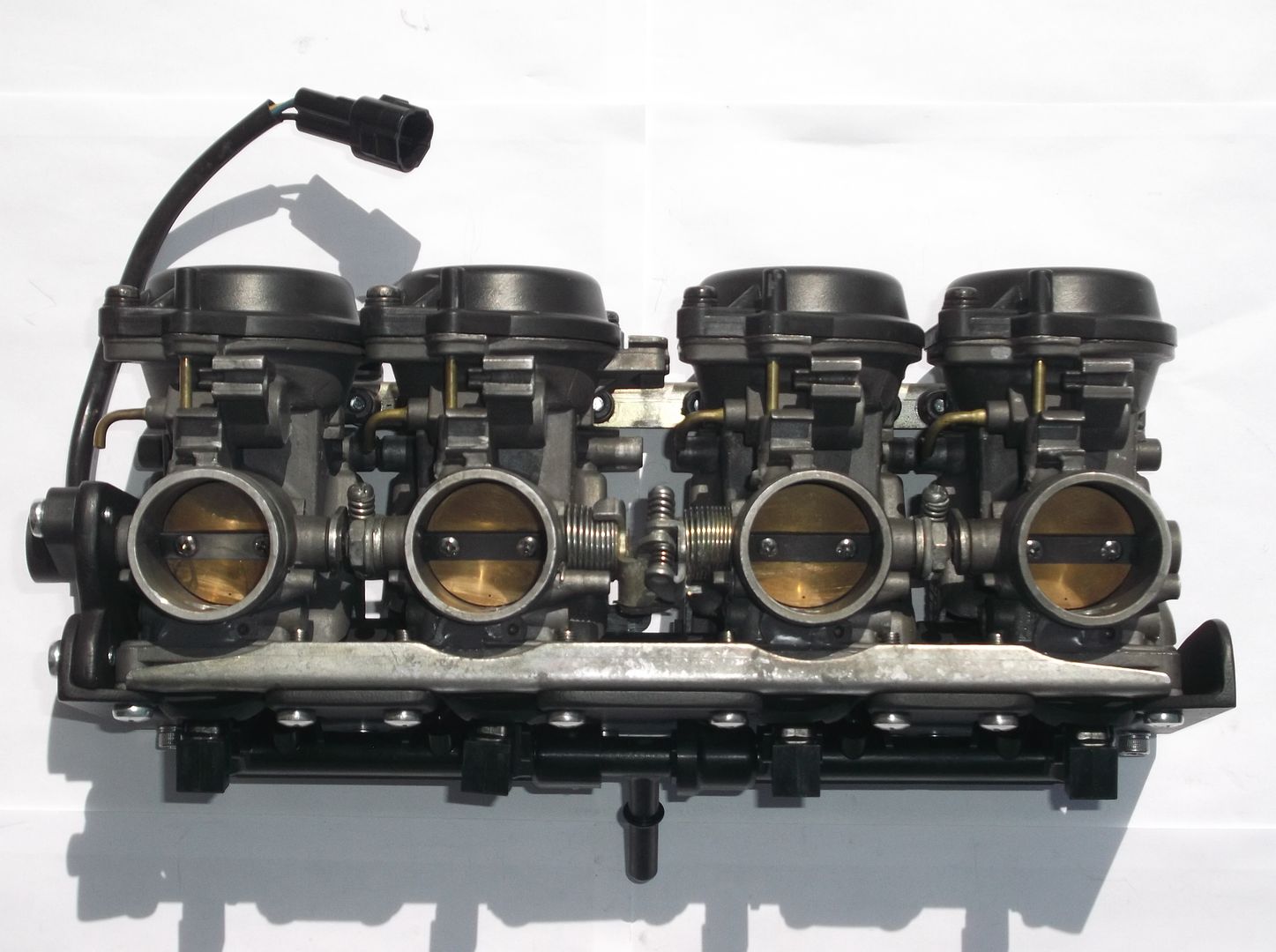
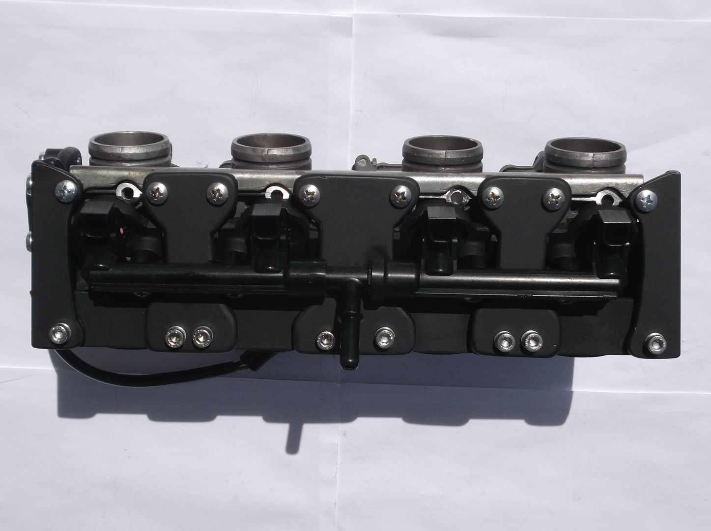
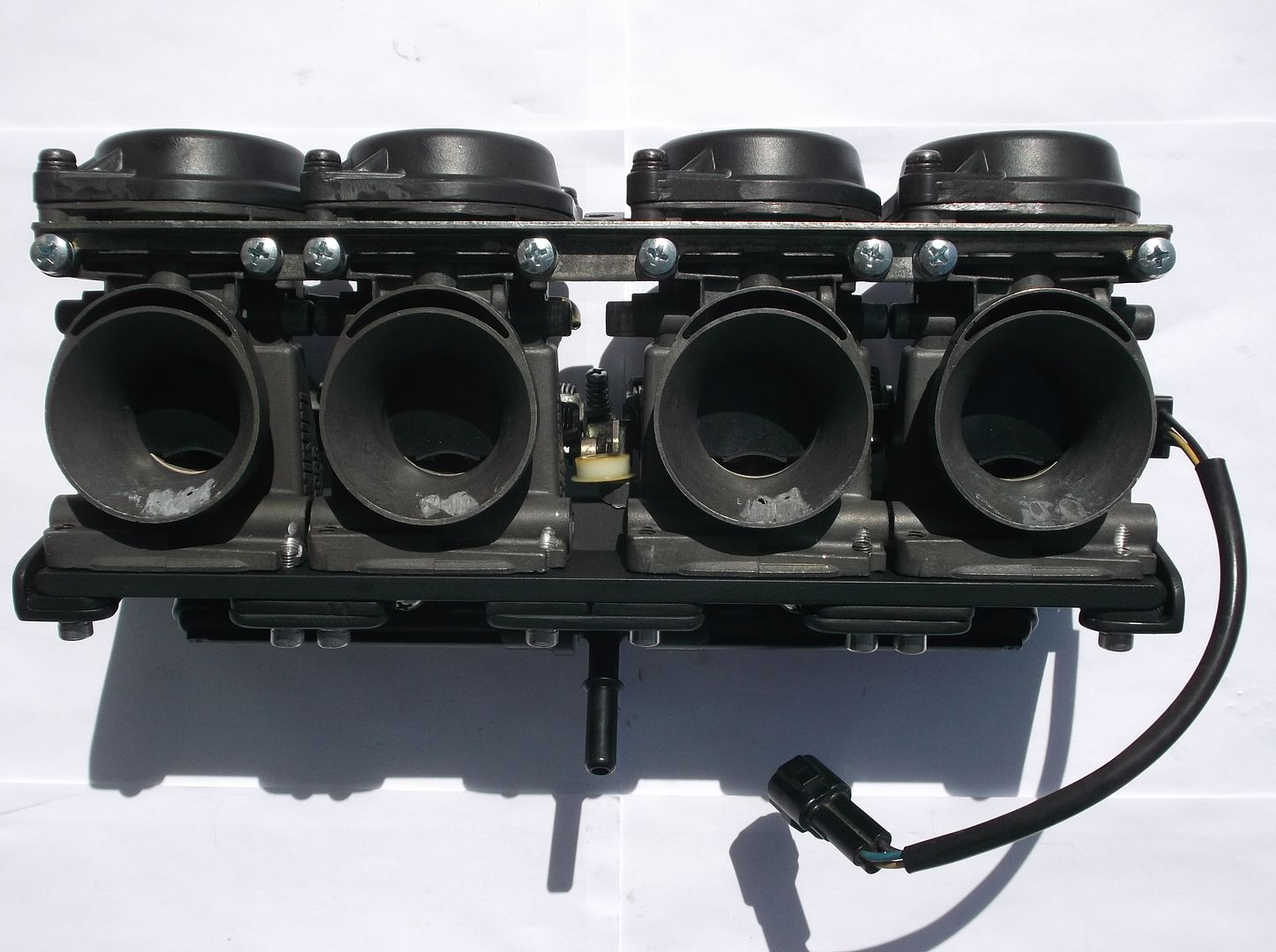
I've been building and riding Do-It-Yourself Fuel Injected motorcycles for about 10 years now. One of my best efforts is my 1993 Suzuki GSF400. Instead of trying to retrofit/modify a set of throttle bodies from another motorcycle I simply turned the GSF400's rack of Mikuni BST32SS carbs into fuel injection throttle bodies. This keeps the fit and serviceability of the original setup which really helps in the areas of long-term ownership and maintenance.
I did a little searching and found that the secondary injectors from a Kawasaki ZX-6R (the set that's mounted on the intake airbox) were a perfect match for the fueling needs of my GSF400's little 100cc displacement pistons. So all I had to do was remove all of the excess plumbing and metal from the float bowl area of the Mikuni BST32SS carbs and get a receiving pocket machined into each of the four carb bodies (with the tip of each injector aiming up into the carb bore just beyond the throttle butterfly. After some experimentation I removed the carbs vacuum operated diaphragms because performance was unaffected.
I fabricated the necessary bracing to locate and secure the ZX-6R injector array into the newly machined injector pockets. And I added a Throttle Position Sensor that was parted-out from a Triumph Speed Triple.
Just an example of one possible pathway to a successful Fuel Injection project (I use the Microsquirt V3 ECU).
Why try to stick with the Honda ECU when the Microsquirt V3 ECU offers you almost unlimited user-control over every input and output parameter? You'll be able to fine tune every single aspect of your 4th Gen's fueling and ignition. There are moments when you feel like a mad scientist (when it's your fabrication and tuning that make is happen).
There's even a way to achieve Full Sequential Injection Control without a camshaft position sensor (using the Manifold Absolute Pressure signal from cylinder #1, which is just as reliable as a camshaft position sensor).
-
I appreciate the amount of effort you're putting into cleaning out the inside of the bike's cooling system. But the proverbial "last mile" in heat rejection occurs where the aluminum of the radiators meets the free-flowing air around it. When I recently purchased my "new to me" '99 VFR800 I found that the radiators were covered in a layer of road goo and grime (especially on the inside, I guess the front tire throws up a lot of stuff) and there was a lot of tiny rocks and road debris stuck in between the individual fins of the radiators. To get them properly clean I ended up having to take the radiators off of the bike.
-
1
-
New 5th/6th/8th gen performance header now in production in USA
in Exhaust Systems
Posted