NVR2L8
-
Posts
202 -
Joined
-
Last visited
Content Type
Forums
Profiles
Gallery
Blogs
Downloads
Events
Everything posted by NVR2L8
-
Also interested... Let us know when you nail down the prices and if you'll be offering a combo front/rear price.
-
 Very Very Very nice...
 -
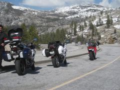 That pic was taken on June 19th 2010, but given this winter's snowfall who knows when Tioga Pass will open this year. It typically opens the first week of June...my guess is two weeks later than normal. PS: I'm kicking around an idea of doing another 4-day Sierra Nevada Ride sometime in either late August or early September.
 -
-
When splicing I always try to get as much wire into the connector as possible, and as long as you have a good mechanical connection at the splice points then they are probably fine. The problem with the stator wires, is that when the engine is at typical operating speed (5K rpm or more) the stator is continuously pumping out about 60 volts AC per phase. Current flow is what's burning wires and melting connectors, so if there is too much amperage flowing through these wires, then you have to look at the R/R since it regulates the current flow from the stator. If you're still burning stator wires and don't have resistance in your repairs, then you might have something else going on with your electrical system. This is a really good guide to troubleshooting the stator and R/R: http://www.electrosport.com/media/pdf/fault-finding-diagram.pdf
-
What's a good way to make this check? Technically you would want to test a run of wire end-to-end, but that isn't possible with the stator wires because you cant easily get to the ends. But what you can do is test the stator per the service manual. So you'll have to somehow get one of your multimeter leads underneath the insulation of each connector or splice on the side that is nearest to the Rectifier/Regulator, and then connect the other lead to ground. The manual says the resistance of each yellow wire to ground should be between 0.1 - 1.0 ohm (which indicates a good stator), so if you have more than 1 ohm then you probably have an issue with your repair/modification.
-
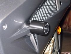
Those splices look soldered to me, and the fact that they burnt at the splice means that you had a bad solder joint. And based on this picture I say that the failure most likely resulted from resistance and not over-voltage, so keep that in mind when you solder wire-to-wire or use solder to fill in crimp connectors. It's always a good idea to make sure the splice did not create any resistance in the wire, especially if the wire handles a lot of current or voltage. They were soldered, I guess I'll have to work on a better connection next time. This was the other end of the splice, showing a lot of heat at the crimp. Were those quick disconnects crimped and soldered, or just crimped? Either way, you can see evidence of heat there too. But that's exactly how I bypassed the OEM stator connector on my bike, and now I'm wondering if my quick disconnects are also burnt. I don't know what to say about these connectors, except that maybe you used quick disconnects smaller than 14 gauge? If so, as a general rule of thumb then I don't anything less than 14 gauge would be capable of handling the current flow that each phase of the stator is capable of producing. FYI...on a 12 volt system, for a short length of wire 14 gauge is rated at 30 amps, but 18 gauge is only rated at half that.
-
Those splices look soldered to me, and the fact that they burnt at the splice means that you had a bad solder joint. And based on this picture I say that the failure most likely resulted from resistance and not over-voltage, so keep that in mind when you solder wire-to-wire or use solder to fill in crimp connectors. It's always a good idea to make sure the splice did not create any resistance in the wire, especially if the wire handles a lot of current or voltage.
-
Misc
-
-
From the album: Misc
© ©vfdiscussion.com
-
6th Gen - Blue Connector Ground Fix - How To.
NVR2L8 replied to KanadianKen's topic in Sixth Generation VFR's
Yea, the green wire on the front side of the blue connector is missing if you've had the recall performed. I think I mentioned that in my post above... -
When it comes to the electrical system affecting how the bike runs, I think the VFRness pretty much takes care of the voltage and current capacity/load problems on the 6th Gen bikes. The only other thing is to try a PCIII, as it really helps with the VTEC transition on my bike. Too bad we're on opposite sides of the planet or else I'd let you try my PCIII to see if it makes a difference.
-
If you as me, the VTEC engagement spot is a tough area to try and hold a steady rpm, and I would think a little surging would almost be normal as the engine transitions from 2 to 4 valve operation. I don't know if you're running a Power Commander, but I have a PCI USB and with Cozye's map, the VTEC engagement is a lot less abrupt and manageable. I still get a little surging though, so I try to either be above or below the VTEC sweet spot. Having said that, aside from the VTEC surge, I think most of my surging problems have been caused by other electrical issues. If you read my posts, you'll see that I noticed a big improvement when I replaced the battery, and just recently I noticed that my low speed mid rpm problems seemed to be coming back again. I thought a new battery was in my future... Just last week though, my Starter Relay fried and the connector mating to it was melted, but after I replaced both I noticed another improvement in how the bike ran. Anyway, if the VTEC area is the only place where you have surging problem I suggest a Power Commander and Coyze's map. If you have surging in other areas, I'd start looking at electrical improvements such as Tightwad's VFRness.
-
6th Gen - Blue Connector Ground Fix - How To.
NVR2L8 replied to KanadianKen's topic in Sixth Generation VFR's
I'm not 100% sure if the blue connector ground wire mod completely eliminates the need for the front wiring harness replacement, but with the new recall front harness, the ground wiring for the headlights is now routed to the right side of the bike and is tapped into the RR wiring instead of going through the blue connector. -
6th Gen - Blue Connector Ground Fix - How To.
NVR2L8 replied to KanadianKen's topic in Sixth Generation VFR's
Well, so far I haven't heard of any front wiring harness problems (buzzing, no headlights, etc) from those of us who had the recall performed. Discoloration of the 30 amp fuse wiring is another story... :biggrin: -
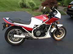
 I would love to own this bike...very nice!!!
 -
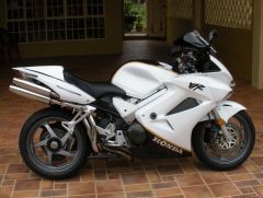 Is your tank painted? Or is the black part a tape kit?
 -
 My bike made the front page!!! Woo Hoo!!!!
 -
Yea, and it's a schematic for a European model. Not sure where I got the PDF file that I uploaded to the Downloads section...it was someone on this site though...but I do know that it's the exact same document that the dealer showed me when my bike was in for the recall. Anyway, that is the file that needs to be approved.
-
-
I got it...shoot me an email address to send it, or maybe I can upload it here? Edited: I uploaded the recall PDF file to the Downloads area, under "Owners Manuals and other", titled "2002-2005 Wire Harness Replacement Recall PDF".
-
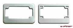
Would this shock reservoir mount work for all the 6th Gen owners who got into the recent Elka group buy? I've never liked how Elka expected us to just mount the reservoir with rubber bumpers and hose clamps, and I sure would like a custom mount for my Elka rear shock ressy, although by looking at your post I'm not sure if I have enough slack in the hose to get it into the position in your photo. Please let us know if it would work though, and if so, if you would be interested in manufacturing more of these ressy mounts. Nice work on everything...you da man!!!
-
Taking a break in Central Washington.
NVR2L8 commented on elevation's gallery image in Member's Gallery
 I grew up in Wenatchee and those ribbons cliffs look familiar. Was this photo taken somewhere along the Columbia River?
 -
I might have to replace my tensioners soon, but even without pulling the throttle bodies, I'm wondering why the front is all that hard to access. I can't say for sure looking at this picture, but isn't that the tensioner just to the left of the fuel regulator? If so, then if you remove the fuel regulator, then it looks like there is plenty of access and replacing it should be a breeze. Yes/No? I've had the fuel regulator off and aside from losing a little fuel due to pressure in the line/rails, it really easy to remove/install it. Also, if I order the tensioner, gasket, and sealing washer, so I also replace the pads too?
-
Quite a few people have used the space by the rear brake reservoir for storage or to mount aftermarket accessories. But the space is only available if you have a non-ABS 6th Gen...on ABS-equipped models that space houses the rear brake modulator and a bunch of ABS plumbing. Same goes for the open space at the top forward area under the left side cowl...this is where the front brake ABS modulator is mounted.