


HispanicSlammer
-
Posts
6,954 -
Joined
-
Last visited
-
Days Won
61
Content Type
Forums
Profiles
Gallery
Blogs
Downloads
Events
Posts posted by HispanicSlammer
-
-
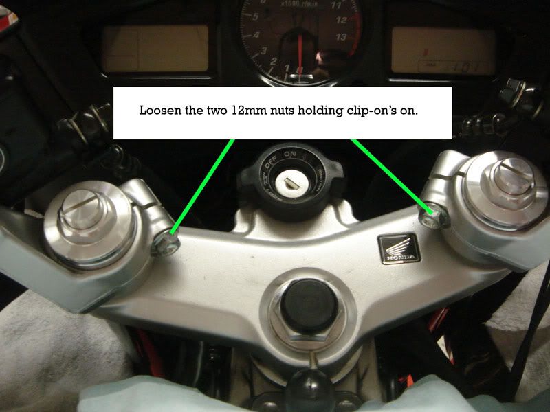
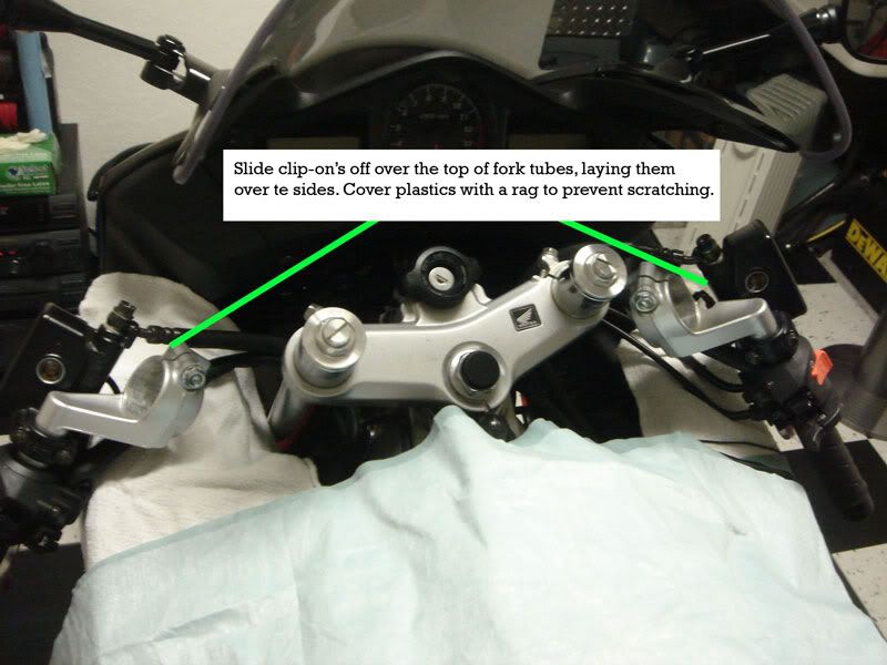
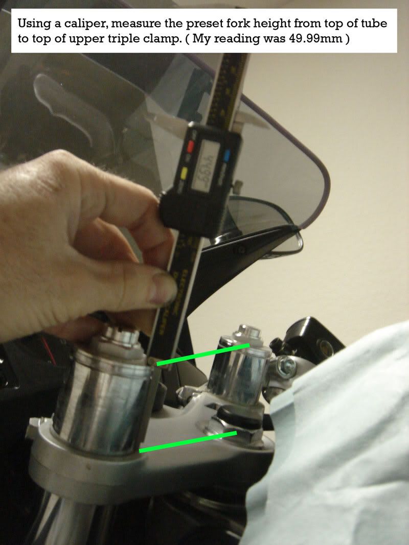
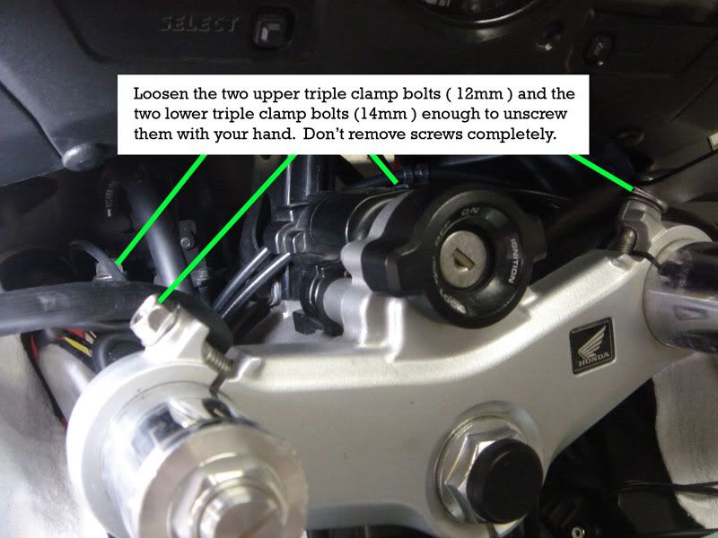
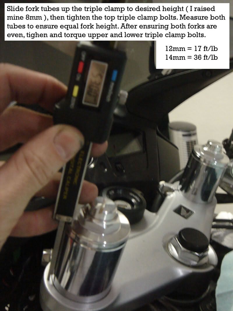
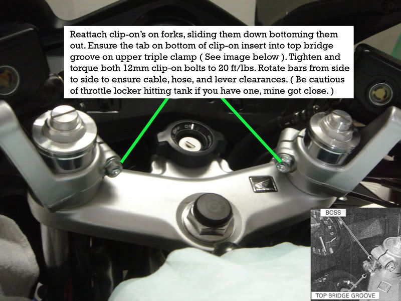
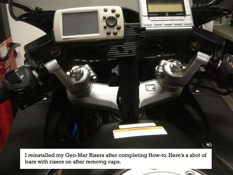
Was raising my forks up the way I had them before I took the bike in for warranty work on throttle cables, figured I would do How-To in case anyone was interested that was unsure what to do. Enjoy!
Cover tank before you start, in case you drop a wrench or something. I've learned from experience.
Edit: Forgot to mention, raise the front of the bike up before you start. The bike will come crashing down from the weight when you loosen the 4 triple clamp bolts if you don't. I put mine on the center stand and pulled the back down with a tie-strap.
-
I have been using my reusable scotts for a few years now myself, and I get a jug of oil at wally world - mobile one 10w40. My buddy Mark did a lot of research on viscosity ratings and such and he spends the 8 bucks a quart on mobile one mtx 4stroke motorcycle oil - me I think its wasting money however I change my oil every 3k unless I am on a 5k trip or somthing where changing oil is unfeasable.
-
Is that a roll of quarters or is your bike happy to see ya?
-

I recently replaced my chain [EK 530ZVX, in CHROME!] and front sprocket [AFAM 17T], along with installing a FactoryPro shift kit. I chose to use EK's Screw-Link instead of buying a cheesy chain tool or trusting a bike shop to do it, etc etc as has been discussed here many, many times. But my problem was that there was very little information out there on exactly how to install it and if it was reliable. In fact, all of the vendors who sell it had little or no idea how it was installed, and some even had it totally wrong!! I Googled the crap out of it, but only our own BatBike Chris had used it, as far as I could tell. He said good things about it, so I decided to give it the full engineer's test and evaluation program. Finally, I got my hands on a many-times-faxed copy of EK's broken-English directions, and away I went.
Let's talk about the testing first, then go back to the install procedure. After I installed according to directions and my best judgement, I rode the bike hard for a few days, making some extended 3-digit speed runs. Then, [since I had bought two link kits for testing purposes] I tried my darnest to pry the sideplate off.

trying to pry.JPG
That didn't work, so I ground the ends of the rivets down, at varying levels of destruction, and pried some more. No luck. Finally, I ground nearly all the way through, and centerpunched the pins out, no problem. So, we now know they're removable, if you work at it. We also know they won't pop off in a hard sweeper!!

ground down pins.JPG

ground down more.JPG
I won't go into the chain install, but suffice to say that when you get it on, with the tension adjuster all the way forward and "loose", the unmade chain ends want to be at about 2 o'clock on your rear sprocket, like this.

new link going in.JPG
I used the x-rings that came with my new chain, and the lube pack. The Screw-Link didn't come with lube (or instructions).
So, once you have the link in place with lube, o/x-rings and the sideplate is pushed on, you run the little black nuts onto the pins finger tight only. IMPORTANT: 1) the nuts have a slight chamfer at the threads on one end only that goes against the sideplate. If you muff this, you'll wring off the pin prematurely. 2) run the nuts in finger tight only. There's a reason for this that I'll get to next.

nuts finger fight.JPG
Once you're finger tight, you take a 5/16 or 8 mm wrench [iMPORTANT: little short wrench, please, NOT a 3/8" ratchet that's a foot long!!] and alternatively turn each nut 60 degress, or one hex flat. This is very important to do gradually and correctly, so that the sideplate is evenly pressed onto the pins. Remember, one hex flat at a time, alternating!
Eventually, the nuts will stop turning with the same basic amount of effort you've been using all along and won't want to turn any more, assuming you're using a little short combination wrench like I begged you to, above. There is no torque spec for this. You simply turn a hex at a time until you evenly press the sideplate onto the pins and the nuts "stop". Now your remove the nuts and throw them away! Have a look with a magnifying glass at where the pin and sideplate meet, and see how it all looks. You should see a very small sliver of the pin where it meets the sideplate, indicating the plate is fully on the pin with an interference fit. If you feel like you should press the plate further on one end of the link or the other, you can replace the nut(s) with the chamfer facing the link, and give it a tiny little bit of rotation, but be careful and don't get greedy, because I have more to tell, below. You really don't want to wring the pin off. It won't be fatal, as it will break at the groove nearest the sideplate. But you won't be able to do the additional little "peace of mind" step I describe below.
I mike'd the chain and the completed link. Chain was .898
and the Screw-Link was .876 This was the case for both times I installed the link, so we can assume the link is slightly less wide than the chain. If you use the same chain as I did, you should see these same numbers, of course.
Another interesting thing--as I was cranking the nuts down, I frequently removed them to see how the process was going. Once I loosened the nuts with the wrench, the nuts easily went off and back on with fingers only. However, once the nuts quit turning and the pressing action was complete, I noticed that the nuts would no longer come off by fingers once loosened by the wrench. I assume that at this point the pin threads had stretched a bizillionth, making the wrench sorta required for nut removal, unless you have real strong fingers.
So now if you're satisfied with the job, you simply snap the long ends of the pins off. It's real easy, using a basic plier.

nuts done, snapping pin.JPG

all done, sweged proper.JPG
So now, you're done. But as promised, I have some more good news. As it turns out, these black nuts aren't metric (!!), they're a good, ol' 10-32 thread. And if you notice, there's a few threads left after you snap the pins off!! So, I know what you're thinking---put the black nuts back on for safety. Wrong. They're way too long and hit inside the front sprocket cover. But, as you can see below, you simply use a quality 5/16 10-32 nut. Stainless would be cool! Do this: using lacquer thinnner or brake kleen, very thoroughly clean your hardware store nuts and the few remaing pin threads. Apply a dab of Loctite to each nut and thread onto the remaining pin stub. IMPORTANT: I torqued these nuts to a mere 30 inch-pounds, and I could feel the few meager threads beginning to yield. So, DON"T crank these nuts down, it's NOT necessary. [Remember the grinding I had to do to get the first link off? It's a tight interference fit!] Allow the Loctite to do its job to hold the nuts in place, giving you total peace of mind. These little nuts are the exact same length depth as the remaining pin stud, so you can be sure it will clear all the stuff up forward in the front sprocket area, but I stronly suggest you run it through by hand like I did before I fired it up for a test ride. Note: My addition of these "safety nuts" is not part of EK's directions. They provide little o-rings that go on the groove for the same purpose. I'll take the Loctited nuts, thanks. Another concern: If you have the stock sprocket, these nuts might touch the rubber damper. But since you're changing the chain, you'll be replacing the sprocket(s), so get an aftermarket and don't concern yourself with the false belief that the stocker is "smoother" or "quieter". It's not true, trust me on this one. You won't hear anything over your slip-on and your helmet, anyway. And nothing is "smooooother" than a new chain.
10-32 nuts installed.JPG

nut comparison.JPG
You'll need to tension your new chain, of course. I have no advice there...I'll leave that can of worms alone, along with the type of oil I use and color of
-
I recently replaced my chain [EK 530ZVX, in CHROME!] and front sprocket [AFAM 17T], along with installing a FactoryPro shift kit. I chose to use EK's Screw-Link instead of buying a cheesy chain tool or trusting a bike shop to do it, etc etc as has been discussed here many, many times. But my problem was that there was very little information out there on exactly how to install it and if it was reliable. In fact, all of the vendors who sell it had little or no idea how it was installed, and some even had it totally wrong!! I Googled the crap out of it, but only our own BatBike Chris had used it, as far as I could tell. He said good things about it, so I decided to give it the full engineer's test and evaluation program. Finally, I got my hands on a many-times-faxed copy of EK's broken-English directions, and away I went.
Let's talk about the testing first, then go back to the install procedure. After I installed according to directions and my best judgement, I rode the bike hard for a few days, making some extended 3-digit speed runs. Then, [since I had bought two link kits for testing purposes] I tried my darnest to pry the sideplate off.
trying to pry.JPG
That didn't work, so I ground the ends of the rivets down, at varying levels of destruction, and pried some more. No luck. Finally, I ground nearly all the way through, and centerpunched the pins out, no problem. So, we now know they're removable, if you work at it. We also know they won't pop off in a hard sweeper!!
http://www.vfrdiscussion.com/uploads/1126494639/gallery_4707_678_837769.jpg' alt='gallery_4707_678_837769.jpg'>
ground down pins.JPG
ground down more.JPG
I won't go into the chain install, but suffice to say that when you get it on, with the tension adjuster all the way forward and "loose", the unmade chain ends want to be at about 2 o'clock on your rear sprocket, like this.
new link going in.JPG
I used the x-rings that came with my new chain, and the lube pack. The Screw-Link didn't come with lube (or instructions).
So, once you have the link in place with lube, o/x-rings and the sideplate is pushed on, you run the little black nuts onto the pins finger tight only. IMPORTANT: 1) the nuts have a slight chamfer at the threads on one end only that goes against the sideplate. If you muff this, you'll wring off the pin prematurely. 2) run the nuts in finger tight only. There's a reason for this that I'll get to next.
nuts finger fight.JPG
Once you're finger tight, you take a 5/16 or 8 mm wrench [iMPORTANT: little short wrench, please, NOT a 3/8" ratchet that's a foot long!!] and alternatively turn each nut 60 degress, or one hex flat. This is very important to do gradually and correctly, so that the sideplate is evenly pressed onto the pins. Remember, one hex flat at a time, alternating!
Eventually, the nuts will stop turning with the same basic amount of effort you've been using all along and won't want to turn any more, assuming you're using a little short combination wrench like I begged you to, above. There is no torque spec for this. You simply turn a hex at a time until you evenly press the sideplate onto the pins and the nuts "stop". Now your remove the nuts and throw them away! Have a look with a magnifying glass at where the pin and sideplate meet, and see how it all looks. You should see a very small sliver of the pin where it meets the sideplate, indicating the plate is fully on the pin with an interference fit. If you feel like you should press the plate further on one end of the link or the other, you can replace the nut(s) with the chamfer facing the link, and give it a tiny little bit of rotation, but be careful and don't get greedy, because I have more to tell, below. You really don't want to wring the pin off. It won't be fatal, as it will break at the groove nearest the sideplate. But you won't be able to do the additional little "peace of mind" step I describe below.
I mike'd the chain and the completed link. Chain was .898
and the Screw-Link was .876 This was the case for both times I installed the link, so we can assume the link is slightly less wide than the chain. If you use the same chain as I did, you should see these same numbers, of course.
Another interesting thing--as I was cranking the nuts down, I frequently removed them to see how the process was going. Once I loosened the nuts with the wrench, the nuts easily went off and back on with fingers only. However, once the nuts quit turning and the pressing action was complete, I noticed that the nuts would no longer come off by fingers once loosened by the wrench. I assume that at this point the pin threads had stretched a bizillionth, making the wrench sorta required for nut removal, unless you have real strong fingers.
So now if you're satisfied with the job, you simply snap the long ends of the pins off. It's real easy, using a basic plier.
nuts done, snapping pin.JPG
all done, sweged proper.JPG
So now, you're done. But as promised, I have some more good news. As it turns out, these black nuts aren't metric (!!), they're a good, ol' 10-32 thread. And if you notice, there's a few threads left after you snap the pins off!! So, I know what you're thinking---put the black nuts back on for safety. Wrong. They're way too long and hit inside the front sprocket cover. But, as you can see below, you simply use a quality 5/16 10-32 nut. Stainless would be cool! Do this: using lacquer thinnner or brake kleen, very thoroughly clean your hardware store nuts and the few remaing pin threads. Apply a dab of Loctite to each nut and thread onto the remaining pin stub. IMPORTANT: I torqued these nuts to a mere 30 inch-pounds, and I could feel the few meager threads beginning to yield. So, DON"T crank these nuts down, it's NOT necessary. [Remember the grinding I had to do to get the first link off? It's a tight interference fit!] Allow the Loctite to do its job to hold the nuts in place, giving you total peace of mind. These little nuts are the exact same length depth as the remaining pin stud, so you can be sure it will clear all the stuff up forward in the front sprocket area, but I stronly suggest you run it through by hand like I did before I fired it up for a test ride. Note: My addition of these "safety nuts" is not part of EK's directions. They provide little o-rings that go on the groove for the same purpose. I'll take the Loctited nuts, thanks. Another concern: If you have the stock sprocket, these nuts might touch the rubber damper. But since you're changing the chain, you'll be replacing the sprocket(s), so get an aftermarket and don't concern yourself with the false belief that the stocker is "smoother" or "quieter". It's not true, trust me on this one. You won't hear anything over your slip-on and your helmet, anyway. And nothing is "smooooother" than a new chain.
10-32 nuts installed.JPG
nut comparison.JPG
You'll need to tension your new chain, of course. I have no advice there...I'll leave that can of worms alone, along with the type of oil I use and color of
-
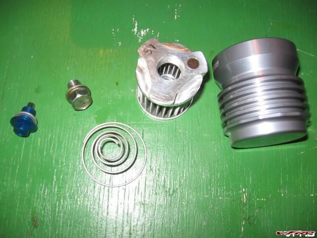
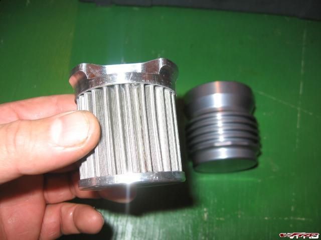
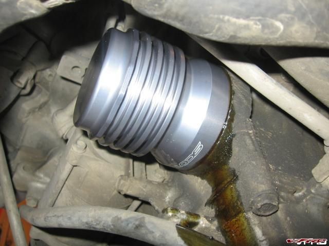
Is there some sort of logical reason Honda would ever put the fuel filter inside the fuel tank?
it contains leaks within the tank itself.
-
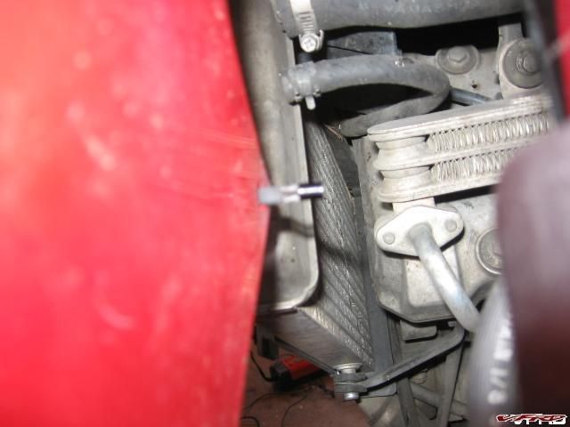
If you notice your speedometer is jumping around or not working at all chances are your speed sensor is wore out, or more accurately the nut that drives the sensor wont make contact with the sprocket bolt anymore.
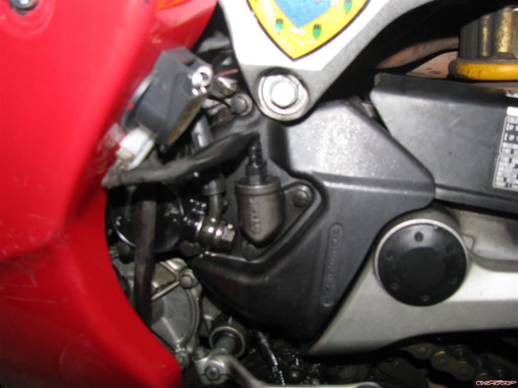
Locate the Speed Sensor it is right over the front sprocket
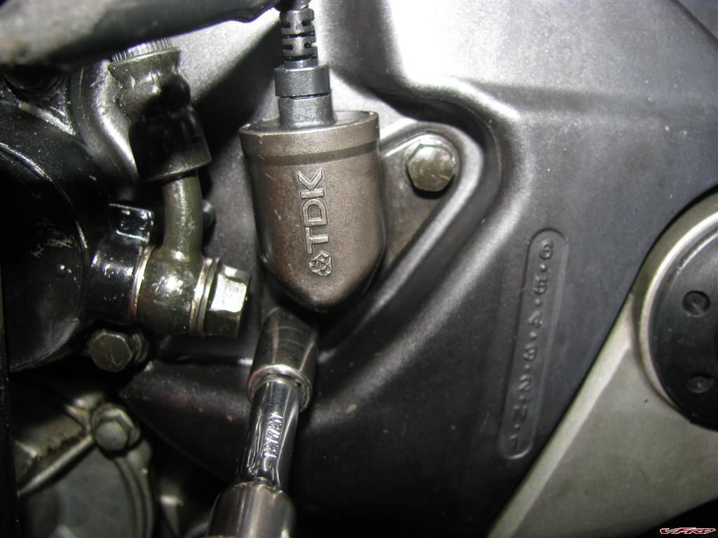
Remove the 2 bolts with an 8mm nut driver
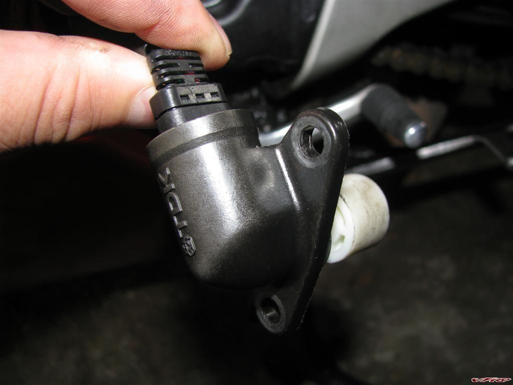
Speed sensor pulls right out
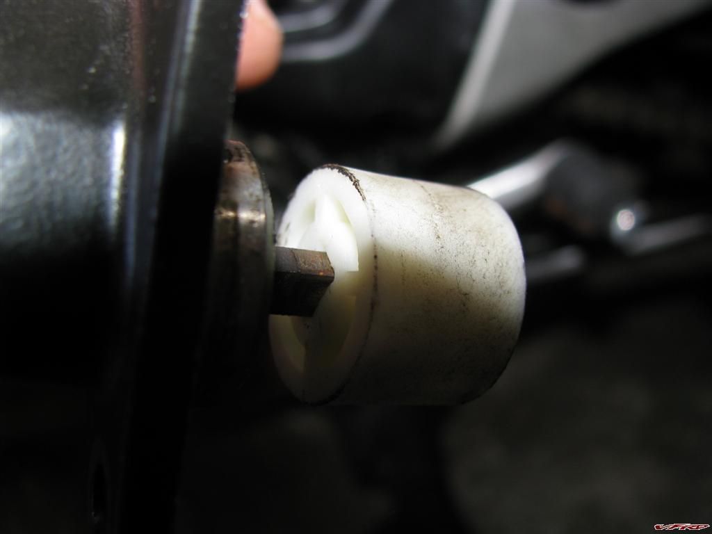
Replace the nylon nut driver the old one prys right off the shaft
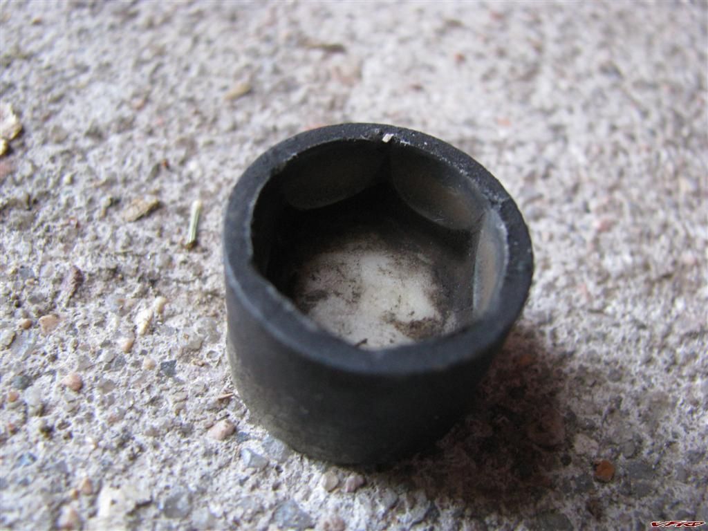
Old worn out nut driver the nylon part would not make contact with the sprocket bolt.
It is a simple 5 minute fix and the replacement nut costs around 5 bucks
Part number 44080-MR7-013 speedometer, joint
-
 4
4
-
 1
1
-
-
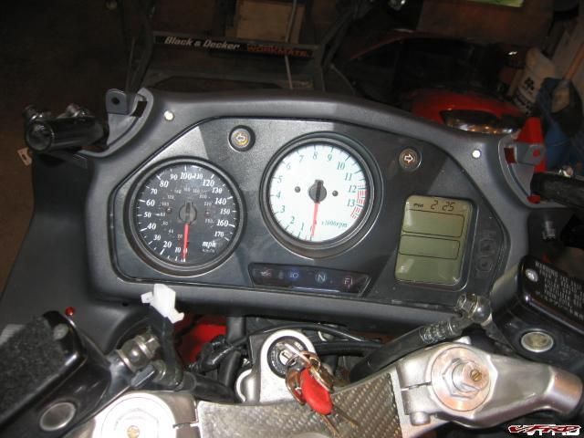
Here you go....

Interesting is that a photo of your computer screen? next time just push the print screen button and copy paste into a paint program
-
approved it just a moment to go
-
How to remove the wheels The procedure is well documented in your owners manual page 171.
To remove the Rear tire,
place the bike on the center stand, remove the mounting bolts that hold the pipe and swing it out of the way. Then loosen the lug nuts and remove the wheel. Removing the Front Tire
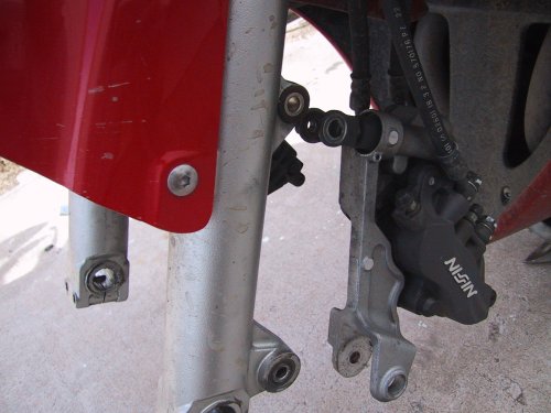
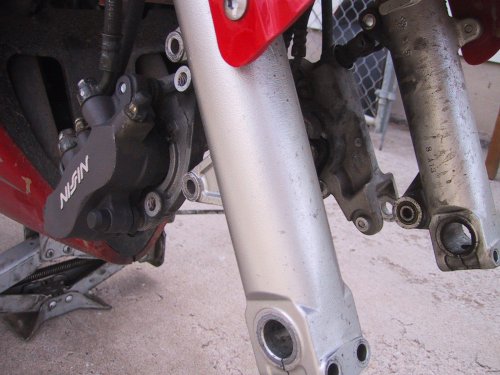
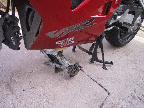
I don't have a front stand anymore so I used a block of wood and a sissor jack, just let the block rest on the header pipes, that is how it is described in the owners manual. Before you lift the bike, Remove the Calipers from the forks first, Left side has 2 hex key bolts, the right has 2 10mm bolts. remove them then loosen the 4 fork pinch bolts at the bottom of the forks. Unscrew the axle bolt, mine was on like a Mutha, It was too tight, but I managed to get it off by getting a pipe for leverage, I almost lifted the bike off the center stand so be carful when loosening that bolt. Once you have that done raise up the front end, then remove the axle, you can put a screw driver into the holes on the end of the axle and twist it out. Remove the wheel. Do not squeeze the brake lever while the caliper is off!
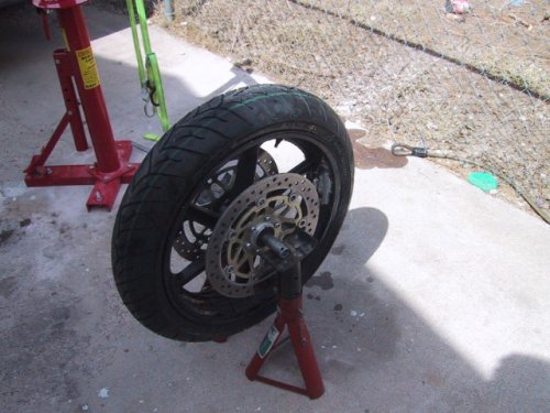
To balance the tire
I used my handy dandy Miguel balance, 2 jack stands and gravity, I spin the wheel several times to find the heavy spot then move the clip on weight to balance it. Came out fine!
Brake Disk Clearance
When replacing the wheel and before you tighten down any of the bolts you must check the brake disk for clearance with the brake pads with a feeler gauge (.028") check to see if the gauge slides in easy if not spread the forks apart or together until the proper space is availible for the disks, then tighten down the bolts!
-
I would like to point out that having the fan on at speed is counter productive since it sucks air into the radiator from the side vents, once you get going at speed the air goes from the the wheel well and out thru those vents the opposite way!
I should pointout that the thermo switch runs that way anyhow, at speed it runs like that by honda spec. The radiator gets hot it turns the switch on, fan runs, at speed or not.
-
I have been following this post for a while now, interesting post for sure, and no I am not appalled by the use of a vfr frame and plastics - that is cool. Never much cared for the look of the old vfrs of the 80's anyway. They where race bikes back then, but most bikes looked butt ugly in the 80's.
I wonder how well that motor can stand up to weather condtions, rain, salt air and stuff like that? I think it will handle better if you can get batteries up front in front of the motor. Keep posting
-
Another post dug up from the dead, I have long since replaced that voltmeter - which was advertized as waterproof. One ride through the fog in San Francisco proved that wrong. I now use a simpler voltmeter.

http://www.signaldynamics.com/products/Modules/HUVM.asp
Led on the top left is the volt meter, led on the right is for heated grips, and vest (green grips / red vest)
-
Ken here are some shots of the 5th gen solo rack installed on my 1998 vfr, using my commuter mini givi hardbag - it came with a universal plate which required me to drill 1/4' holes in the solo rack with some bolts and the givi hardware its really versitile. I think a pad on the back of the mini bag can provide you pillion with back support I think it will work with a passenger!
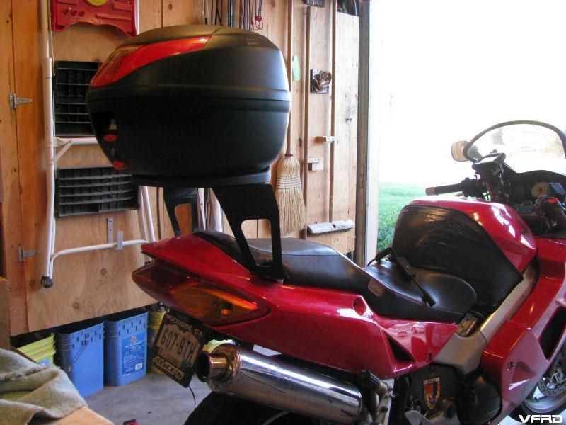
KKens 5th Gen luggage rack
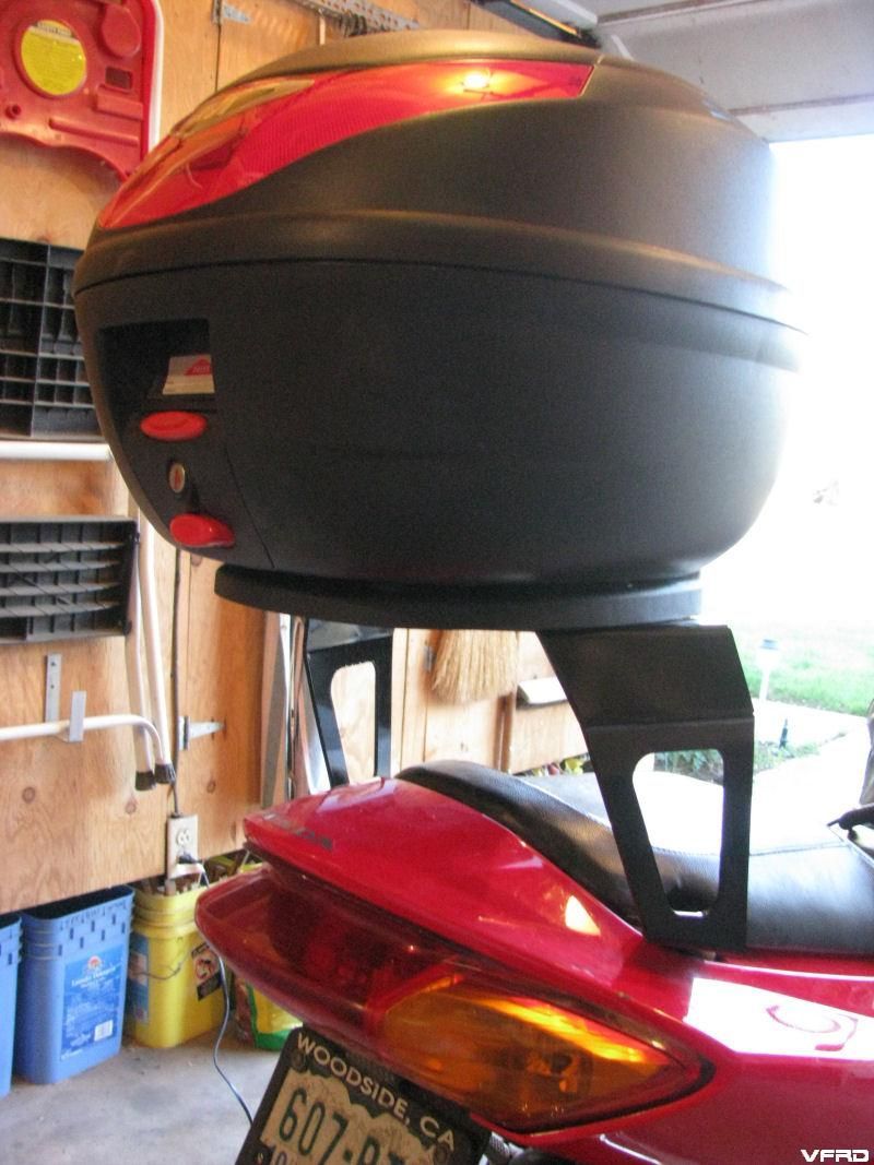
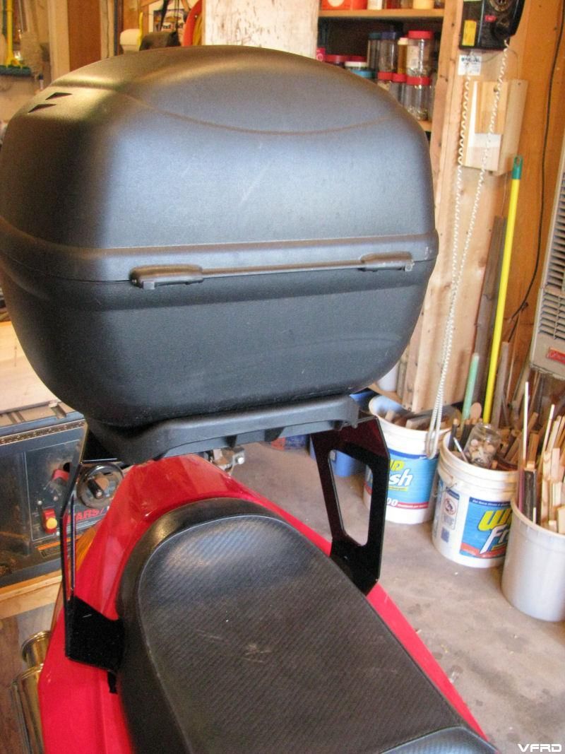
Mini Givi hardbag with universal mount plate
pillion view seat can be easily removed with rack and bag installed
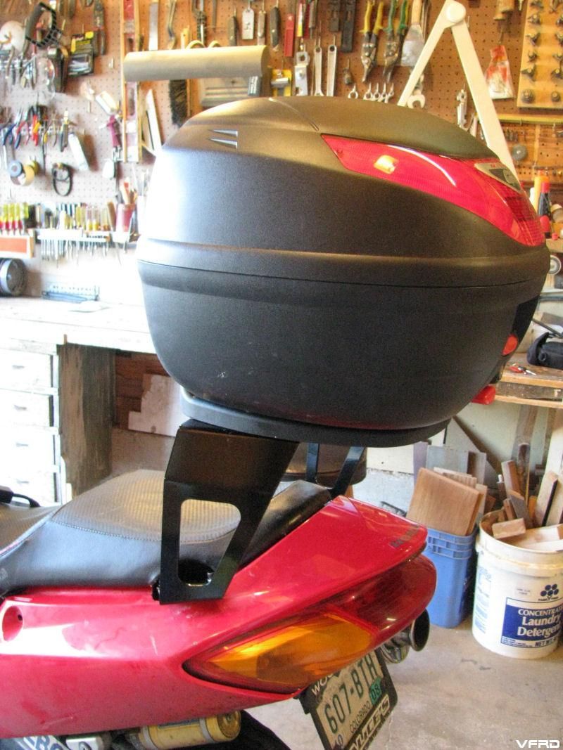
Other Side
I understand you have 20 of these units on hand that you made for vfrd members who showed interest and yet did not follow through. I am here to tell ya the unit is sturdy easy to install and so simple I dont know why I didnt think of it! Much cheaper than a wing rack or other type of rack at half the wieght - I was surprised at how sturdy it was when I installed it. It took forever to drill the holes for the universal givi plate and I had to sharpen the drill bit to get the last one done with my drill doctor!
Good stuff Ken! If you where one of the members who initially showed interest and balked later, its good gear, Ken really made a top notch rack!!
You can get one of these mini givi hardbags for $150 on ebay and have a lockable waterproof commuter hard bag for around $300 bucks and not need to adjust your suspension for a heavy load.
-
The whine from the radar detector was too much so I got a noise filter from the electrical connection and a ground loop isolator
http://www.electricalconnection.com

Noise filters, I used the universal one this is used for power to the radar, a transformer and capactor,

This is the ground loop isolator - stereo, I ended up removing the connectors, and cutting the wires shorter and soldiering the leads together from stereo to mono, this is the same as the noise filter but its smaller and uses two transformers and capactors for different voltage/amps, this is connected from the speaker lead.
It was then that I found a mono isolator from escort - oh well my solution worked great, no more wirring, hissing or popping when I turn on the motor, It did however lower the overall volume of the detector but it was crazy loud as it was. Now the level is just about right
 this one is already mono and it used the correct size lead for a radar
 -
Moved to feature, however two topics on the same topic? I merged to feature both togther - lets make it simple guys - one topic!! Moved sebs up to the first page by merging his post with his first one.
-
I went riding today and tested it out, at first the wind would activate the mic - so I pulled off and turned down the vox control and it worked better. I like that you can hear what you say, however I tend to sing to the music sometimes and that could get embarrasing if the radio is on. so far I like it, the instructions say to switch out resistors on the in ear phone connector box if you need more volume - I will do that.
-
Hey HS, you know you can use your ER6's with the Autocom if you buy this cord too, right??
http://www.autocomamerica.com/product_deta...productid/25785
The straight one is a little cheaper.
http://www.autocomamerica.com/product_deta...productid/25631
Yes I have it routed behind my back protector in my aerostich suit. I have the coiled cable
-
Oh since I took the detector apart I removed the laser sensor and soldiered in wire extensions that I then soldiered the laser sensor to and fished through a hole in the front fairing, its peers out into the wheel well
-
Why did you pick the Autocomm Active Rider Plus system?? What else did you look at? I am have been struggling with this issue for months. On the Wing no problem but on the VFR ???? And do I want to spend the MONEY?
Thanks
I chose the plus since starcom was more expensive, however I think its better gear. There is also that german brand bohr each is similar in concept. The autocom I chose cause it was relativly affordable, and it is expandable if I want to add a radio. Autocom sells a unit just for rider and pillion, then this one, and a delux model that has more options, this one is the middle scale model. Like I said in the last thread I posted, the gov-a-ment is giving it out so I guess I could afford it! Either way the choice its gonna cost $300+ as you ad options. This I did for a better sound and the option to ad radio, I also want to be able to use my bluetooth phone with the zumo - hands free.
-
How does the Radar detector work from behind the fairing? Aren't they line of sight dependant? I would like to install one, but I have two issues:
#1. How do you hear it?
#2. The line of site question
1) It works fine, they are line of sight dependant however the fairing has no metal in the paint to scatter most of the signal, sure some of it gets deflected however it is not enough to make a big difference. No more than behind the windscreen - its not visible spectrum it goes right through. I got a ticket in Ammarillo TX and after reading the ticket found that it is illegal to have a detector there, I had took off my helmet and placed it over the detector so the cop did not see it. I am sure he would have give me a summons had he seen it, so I hid it away behind the fairing, got the notion from dutchinterceptor. I have been warned a number of times of cops running radar and slowed down to keep legal, however instant on poses a threat - which is what happend in Ammarillo, I got his signal alright but he had me and his lights where on as soon as I passed.
2) How do I hear it? the mono speaker output on the detector is plugged into the autocom now, the unit sorts out and mixes the sound inputs from several sources and you hear the radar signal in the speakers, mine has different sounds for different types of signal, and it gets more intense the closer the radar is to the detector. It can get annoying in town when there are other detectors around, or automatic door openers, or those portable speed radar trailers the cops put out and leave there on the roadside.
-

NEW ADDED RADIOS!!
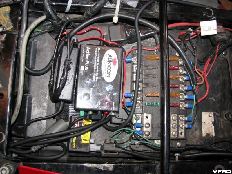
I spent a good portion of the morning installing an Autocom system. I found the instructions to be strait forward, however the equipment was sort of cheaply made. cheap plastic housing and knobs seemed to me to sort of a low quality. The sound however has not been so after testing - it is indeed good sound.
This unit uses 4 pole inputs in three auxiliary ports, and a 4th to be used for a radio that is on a wired connector. You have to sort out what you have that you want to connect to the system then order the right parts that connect to the autocom. I have a cheap ass radar detector that works well enough that I wanted to connect, and a zumo 550 that I use for pretty much everything else, music, phone, and of course gps. I love the bluetooth phone ability. Maybe some time in the future I will get a radio as well but for now its not something I would use. It also comes with a headset, mic boom, and a pillion connector - pillion head set sold separate.
I started with the Zumo connections, this required a zumo box to take signal from the stereo output and a mono mic input for using the phone. These two wires are then routed into a small box that has a 4 pole lead on the other end that plugs into the active-plus.
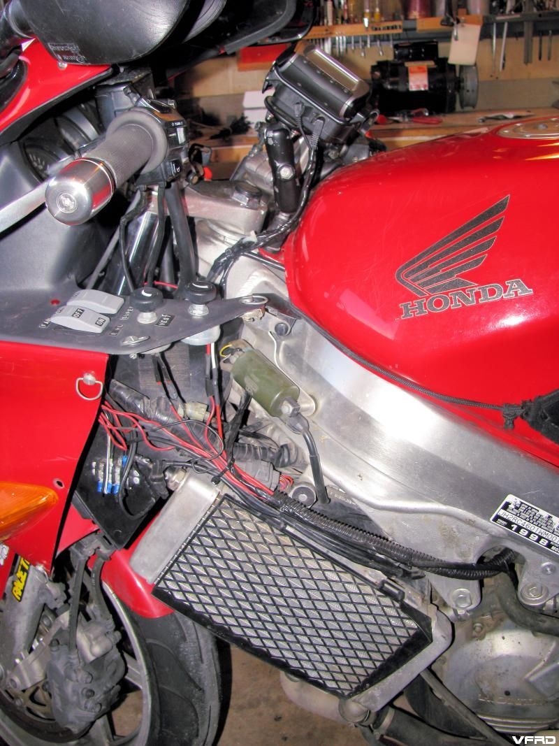
Zumo wires routed on the left side
I decided the wires where too unruly if I hung them separately so I wrapped them with electrical tape together and routed them along side the OEM wire loom and some other existing accessory wires I had installed previously. Then I zip tied them to secure them in place. I must have used up two rolls of electrical tape on this project.
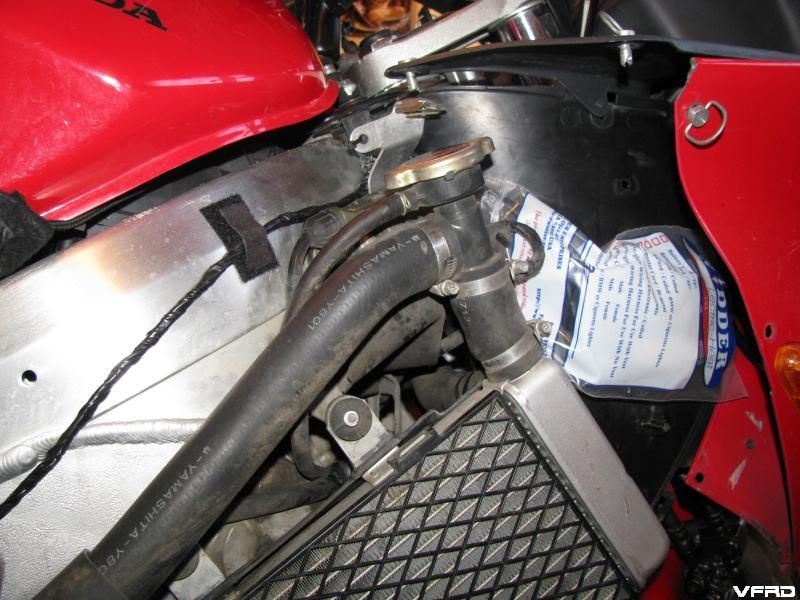
radar detector encased in a plastic bag behind the right fairing new mono lead and power wires wrapped in electrical tape
I removed the radar detector from under the left fairing and installed a new mono lead long enough to reach the system under the seat and hot glued it to the radar detector, I had previously drilled holes in the bottom of the detector case and then screwed into them bolts - then drilled bolt holes into the side of the inner plastic fairing to mount the radar detector, I did a writeup on it a year ago, anyway the power wires where just loose and I put the whole thing inside a heavy duty plastic bag to keep it dry, yes it still works inside a bag and behind the fairing! It works pretty darned good too for a $100 cheap ass Cobra detector. I have a switch on the top of the inner fairing to shut it off when it gets too busy in town. I again wrapped the power leads and the mono lead in electrical tape to secure the wires better and to prevent chaffing.
I had installed a switched power fuse block long time ago I used the same ground on the autocom as the radar to prevent a ground loop hum, however I do get engine hum so I will have to look into some kind of filter for the radar.
This thing has vox control so you just speak and you can hear yourself though the speakers, it mutes the music. There is a little adjustment screw to tune the vox to the correct level so that you don't have false inputs on the mic. I have the wire loom routed behind my back protector in my aerostich suit, I don't like wires hanging loose when I ride slapping around, so I routed them inside the suit. I am used to this from my old system, a bunch of stuff I hooked up together on my own.
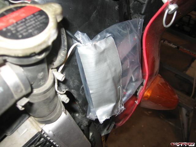
This is how I had the radar detector before, the leads where hanging separate and the bag was thinner and taped shut with duct tape, I used a hot glue gun this time.
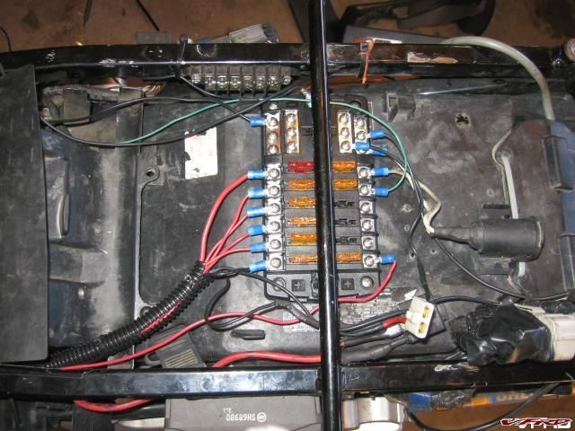
This a picture of the accessory fuse box before I added the speedohealer and the autocom, so powering the unit was just a simple job of soldiering leads to fork connectors.
You can see the zumo adapter next to the active plus unit and how I taped the wires together.

*********
Update
It was suggested that Midland radios where a good option, waterproof and inexpensive, with frs/grms capability, the set I got also have wx NOAA weather channels as well (very handy here in Colorado where the weather changes on the hour sometimes) I got a set of two from Radio shack they came with a couple of vox head sets and a push to talk button. grms radios are high power and require a special FCC licence, FRS is probably more than adequate, but these Midland GTX800 radios are rated for 28 miles in ideal conditions, real world 5 miles is more like it.
I wasnt sure how I was going to deal with the radios, I wanted to be able to shut them off and adjust the volume as I rode or stop to set it up on the fly for different channels, group codes, privacy freqencies and such. At first I was going to just leave them in my tank bag but then I was looking at my junk drawer and I found the ram mount I used for my old gps - a quest unit that died. It thought I could just attach it to my ram ball on the gas tank!
I drilled some holes in the battery cover and slapped on some velcro to help absorb shock and it worked!~
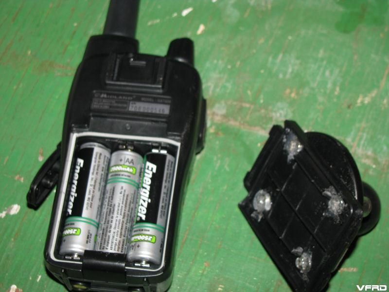
Added frs/grms midland radio set attached a ram mount to the battery cover to fasten it to the bike
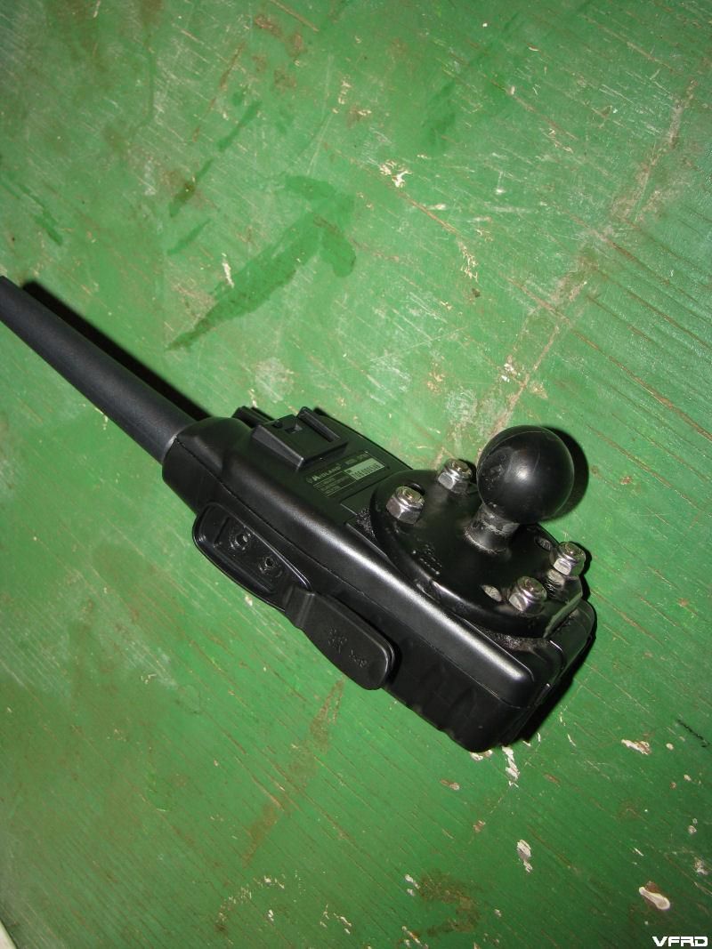
The battery cover just snaps into place it is really secure
I decided to move the zumo to the left clip on so that I can reach it with my glove better, less of a reach, I tend to change music and stuff more often than I thought I would, so I made it more accessable on the left clip on using a special ram ball mount off the clip on bolt hole.
Zumo and Midland radio configured for riding

ram mounts one on the gas tank and one on the left clipon - along with all the wires zip tied into place
I played around with it and had my Dad talk to me on the other radio - sounds good and it transmits clear!
Good stuff
here is a link to the radio shack midland set I got. I had to get a universal radio connector from autocom in order to make it work, routing the line along the side of the tank. I wouldnt say they are waterproof but advertized as such radio shack does not make that claim they reducethe rating to water resistant. At $64.99 for the set they are more affordable than most. I like the fact that you can use the nicad battery they include or use aa batteries, I have a whole bunch of rechargable aa batteries so I use those instead of the nicad pack
http://www.radioshack.com/product/index.js...rentPage=family
http://www.autocomamerica.com/product_deta...productid/25725
coiled or strait
-
I really want to see this thread but it is hacked apart? I see alot of this – and this R’s and this I’. am i seeing things?
I had to convert the database from mysql5 to mysql4 when we moved to the server, it left some strange reminants. Say in the future take it easy on the quotes, there is no need to quote an entire writeup along all the pictures, edit it out for the relevant info then press send the reply. Please - it cuts down on the scrolling and such nonsense.
I really dont know what the odd symbols are nor do I have the time to fix them as its not my work maybe KKen will get to it when he has a chance to rewrite the error text.
-
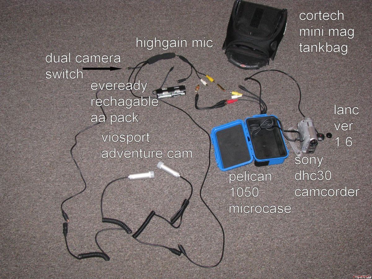
dual cam setup
I have a new/old camera, the canon zr300 went kaput, so I found a sony hc30 on ebay. I prefer this camea for its small size and because it has a Lanc port
my setup is as follows
- Sony DCH30 mini dv
- 2 x Viosport Adventure Cam
- Lanc version 1.6
- Pelican 1050 microcase
- custom made dual camera switch/high gain mic
- audio splitter
- cortech mini magnetic tankback
- eveready rechargable AA battieries
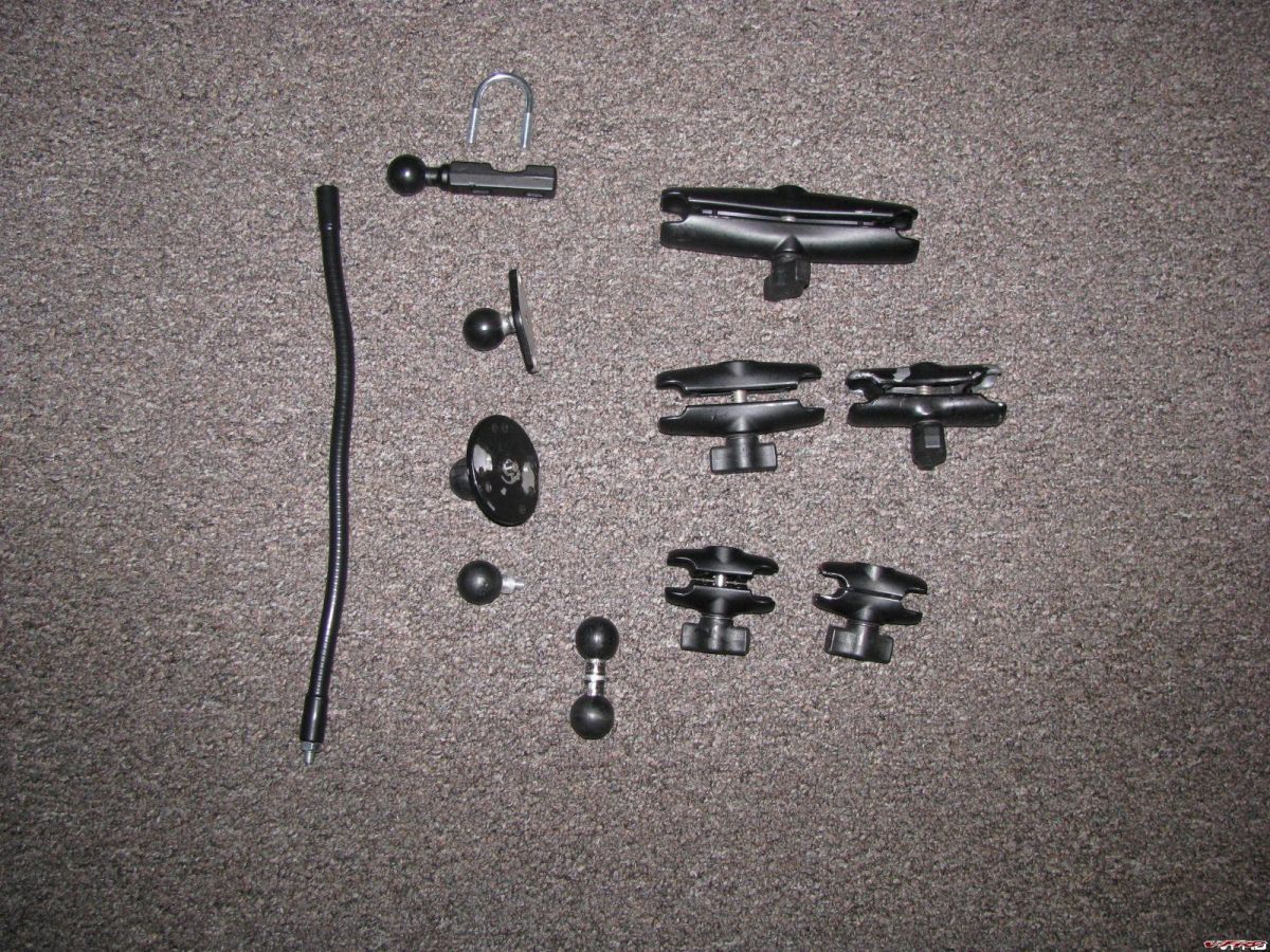
Ram mounts
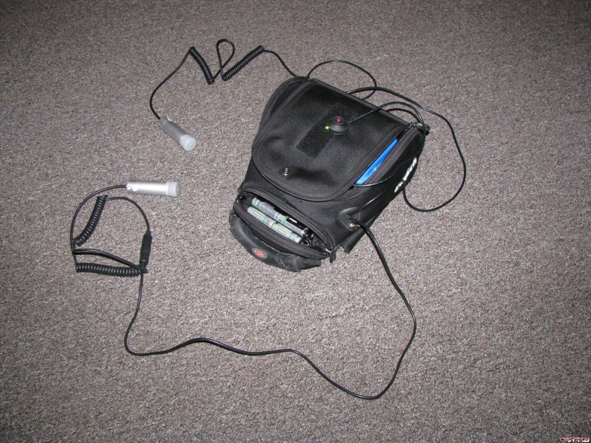
Camera set to go
The Lanc is nice you can shut the camera off and on, pause and record by one button, depending on how long you depress it.
- Sony DCH30 mini dv
Factory Pro Shift Kit And Evo Star install
in Maintenance Guides
Posted
Ok, I would like to start by saying this is my first time making a how to so bear with me here. So if anything is missing or needs a better explanation PM or e-mail me and let me know. And if the photos are to small let me know, the originals are over 3mb each and thought it would be better to bring the size down.
To start, I did NOT drain the coolant, but most of you will want to so you can get the water pump out of the way, I am use to cramped mechanic places so it did not bother me.
First part is easy. Just remove the clutch and speedo. After that there are two (2) bolts holding on the sprocket cover.
As photo says, only two (2) bolts that need to be taken off to remove the water pump, the others hold the two half's of the pump together. There are two (2) other bolts behind the water pump that hold the shift cover on.
If you are taking the water pump off you just remove the hoses and pull off the pump.
As photos says, tight, but can be done.
Watch out for the part in the middle, it has little spring loaded parts in it and they can get lost very easy....Trust me.
Remember how the last two parts go on and line up. Also, when putting everything back, make sure you slide it all the way back on.
When taking the star off it will spin with the nut, just turn it (about one full turn) and it will stop, then remove the nut and the star will slide off. There is a little bump on the back, make sure you line it up with the new star.
I had to put the cover and shaft back on at the same time since I did not take off the pump. This is why I said for most of you its a good idea to take it off as you need the shafts and arms lined up on this! I could "feel" when it was right, but you may not, you do this at your own risk.
I do not accept any responsibility for anything you may mess up or break! I make no guarantee that this info is perfect!