
HispanicSlammer
-
Posts
6,954 -
Joined
-
Last visited
-
Days Won
61
Content Type
Forums
Profiles
Gallery
Blogs
Downloads
Events
Posts posted by HispanicSlammer
-
-
I have about 9000 miles on the veefalo now and I am always getting ready for the next big ride, this season I needed to inspect the airfilter and I just went ahead and bought a K&N online - they are about $50 bucks for a vfr1200 average. I took both pictures and video for this project
http://www.vfrdiscussion.com/uploads/videos/491/fairing.mp4
There is no hd segment so turn off HD, then I took pictures along the way too, and I half arsed installed a few pieces of a tank slapper kit on the most worn parts of the body work of the bike. Install the rest later when time allows.
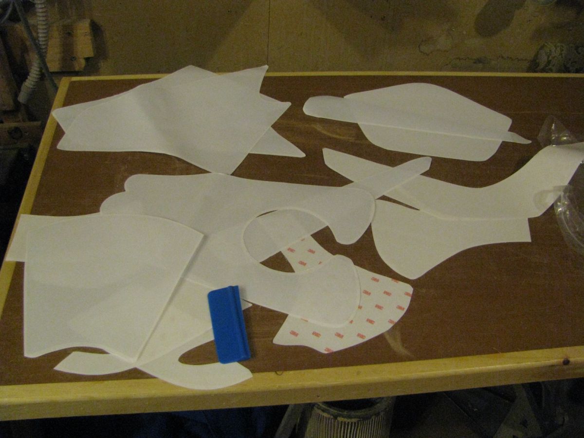
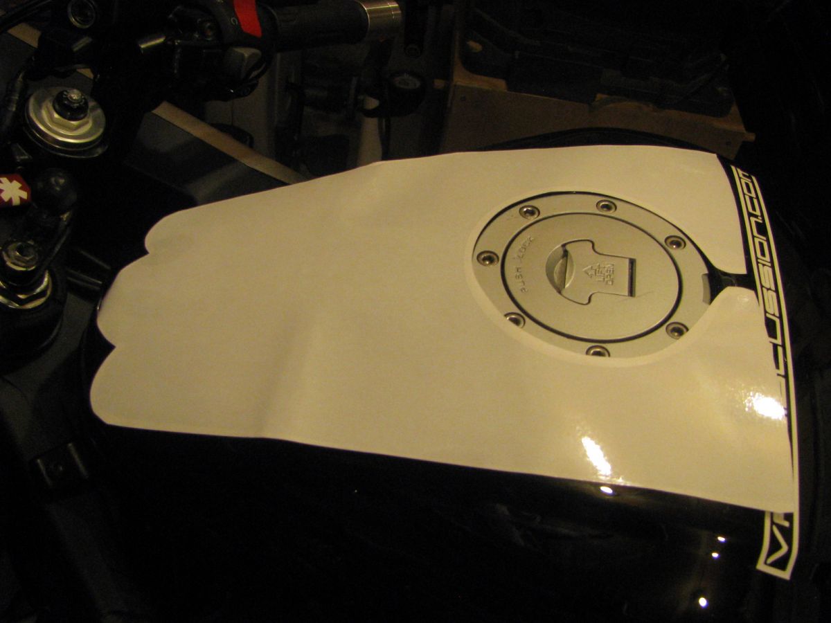
Tank Slapper kit vfr1200 I have only installed one of the front covers and the tank pieces where my jacket rubs against the tank
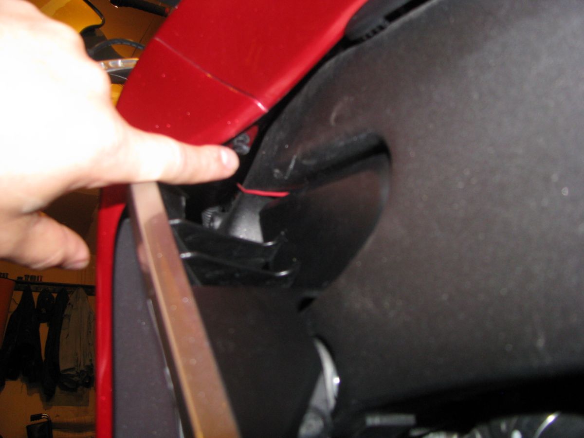
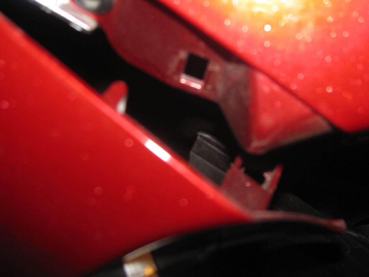
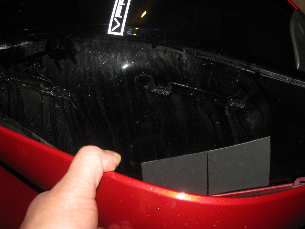
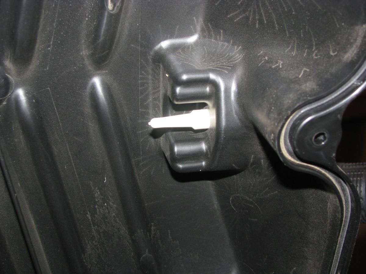
Location of the large plastic fastener
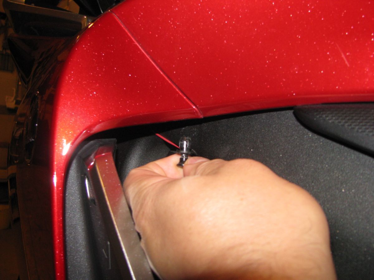
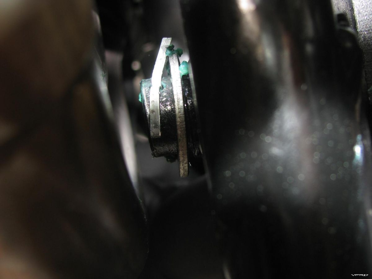
Removing the large snap in plastic fastner this fastens the fairing to the tank cover
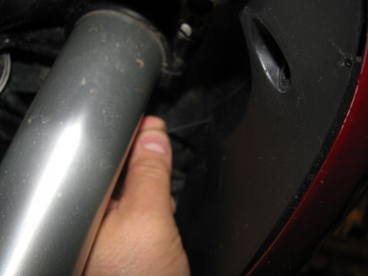
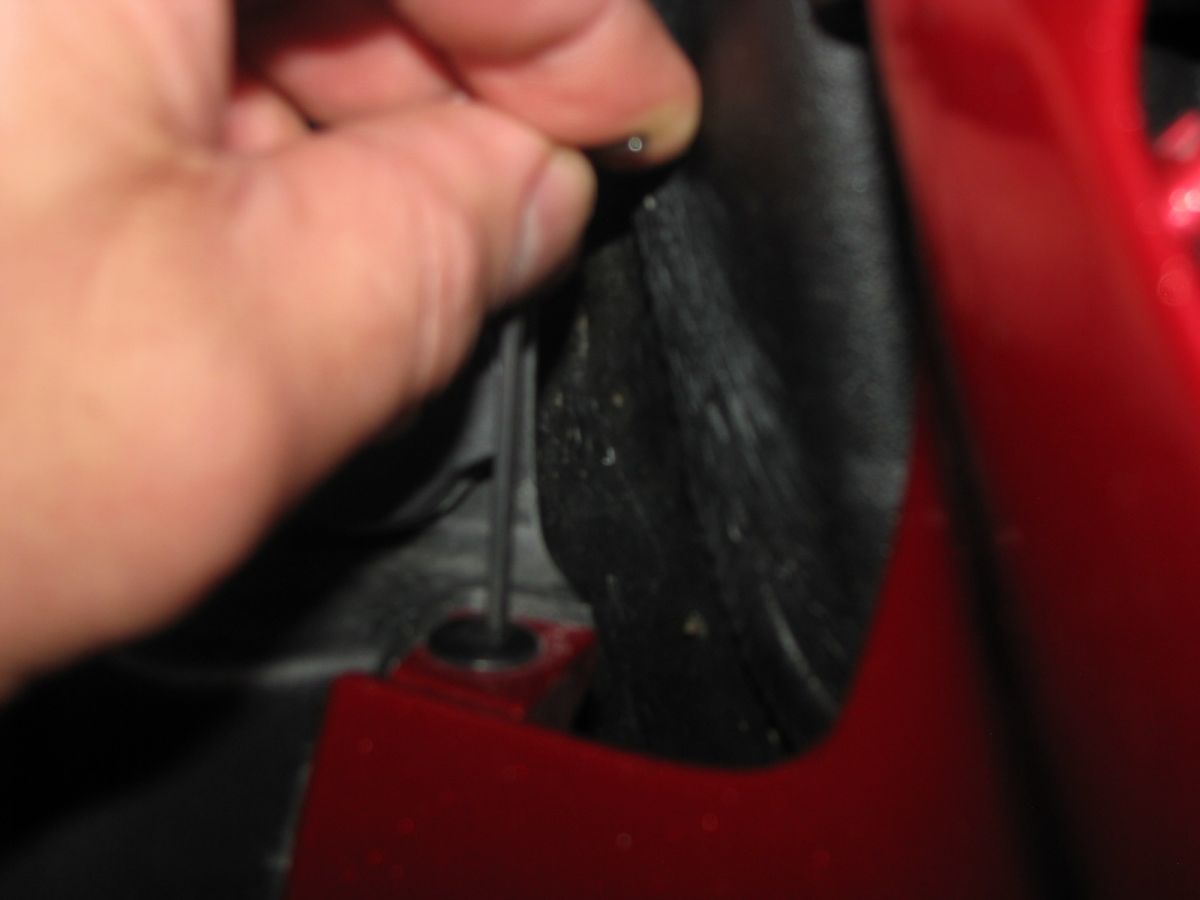
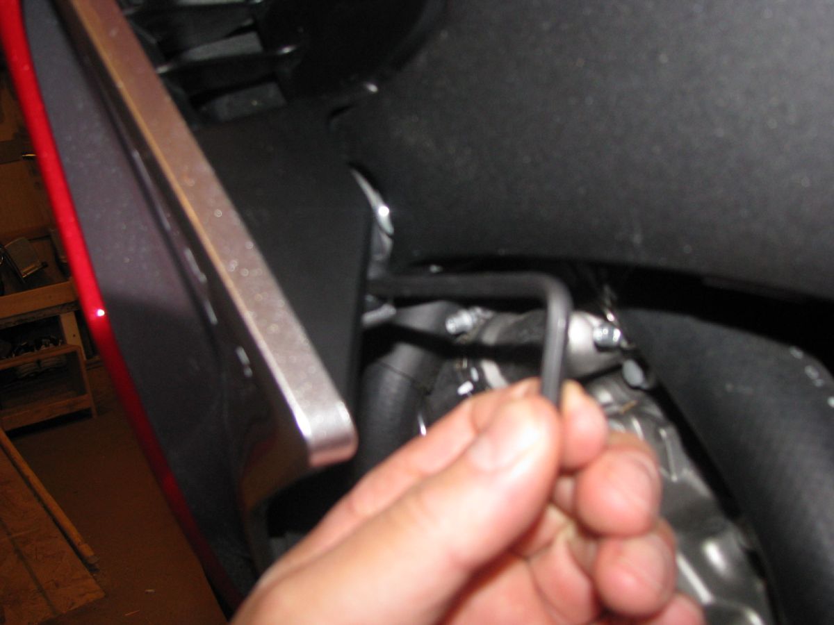
Removing a small plastic fastner left side fairing inside the wheel well hard to reach behind the forks push in the cap and remove the fastener
To reinstall the small plastic fastner pull out the rod or cap this will allow the fastener to be able to fit back into the hole
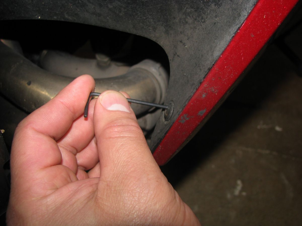
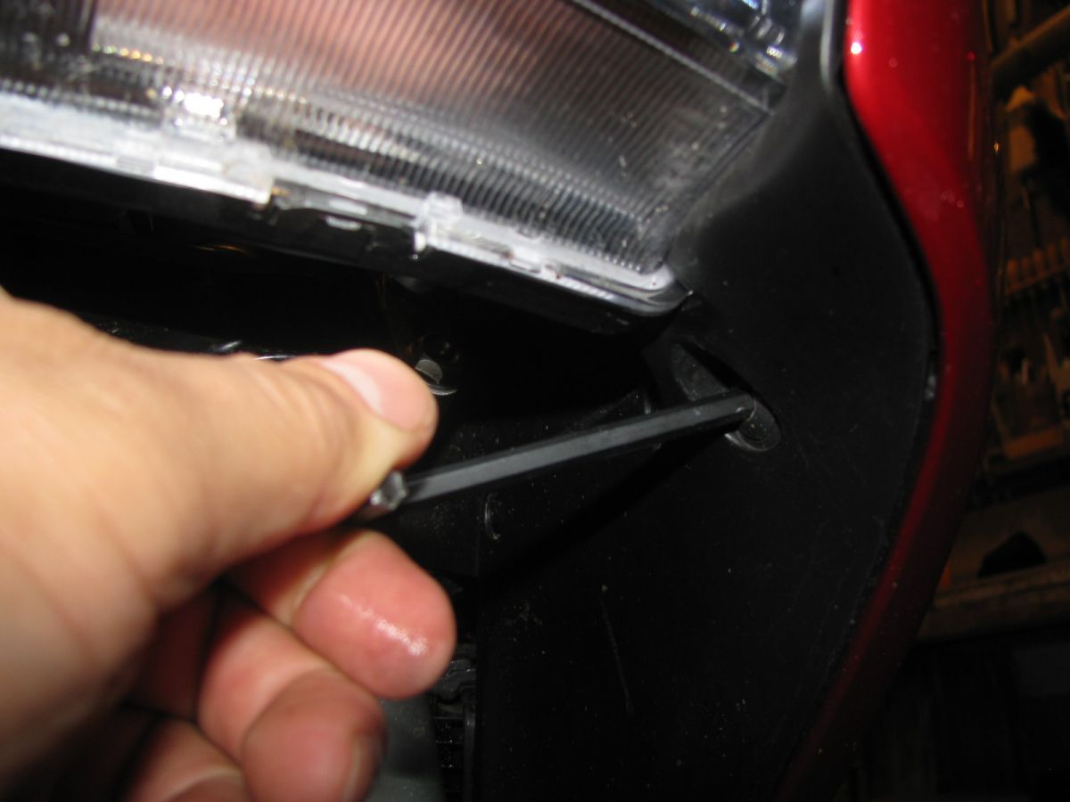
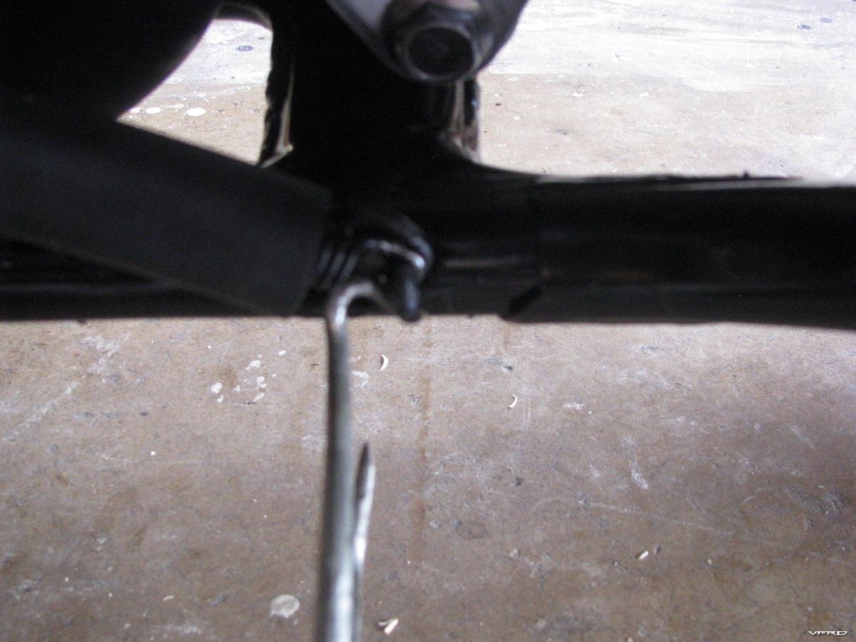
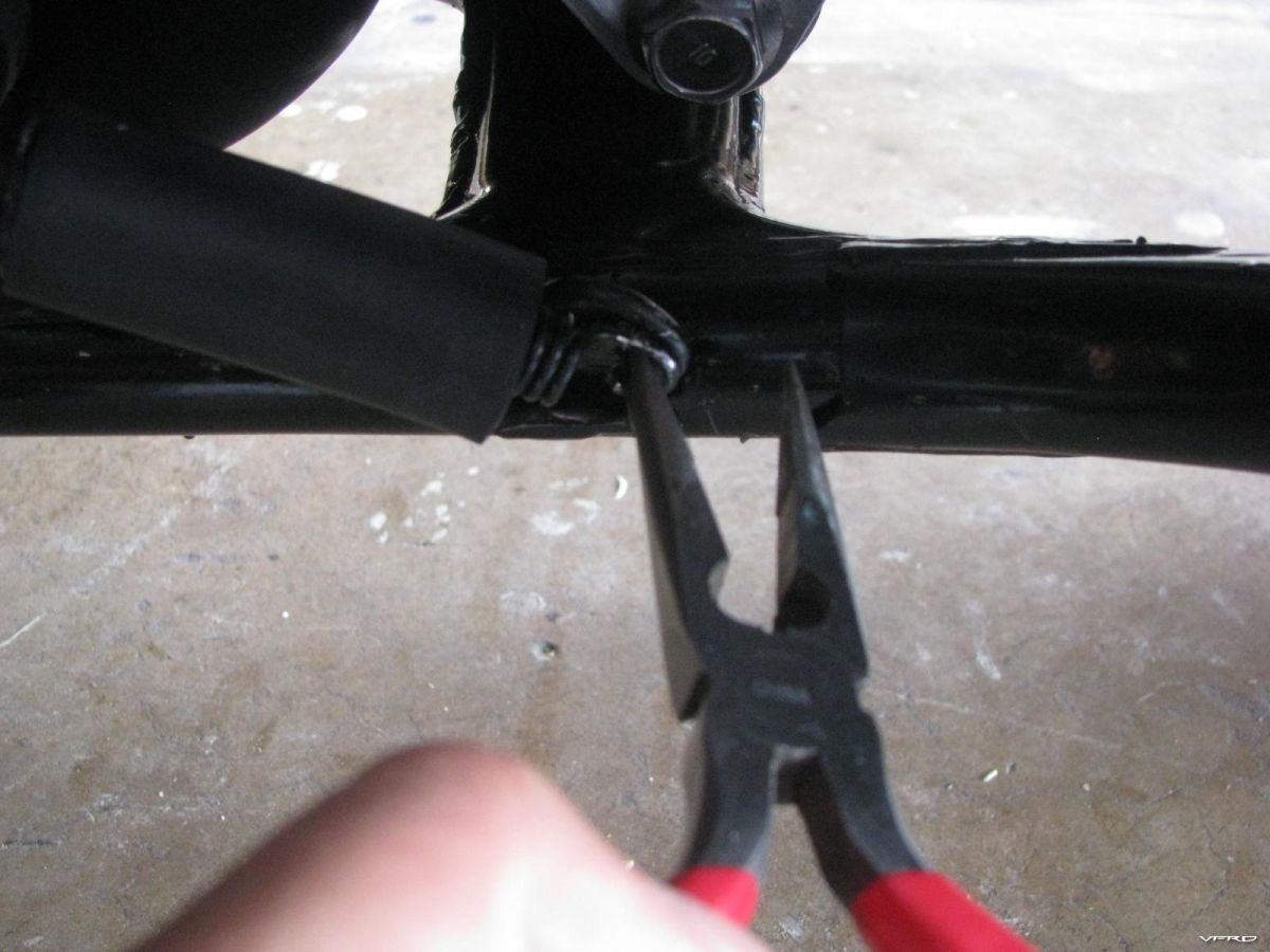
removing the last plastic fastener from the left side fairing lower push in the cap and pull out the fastener
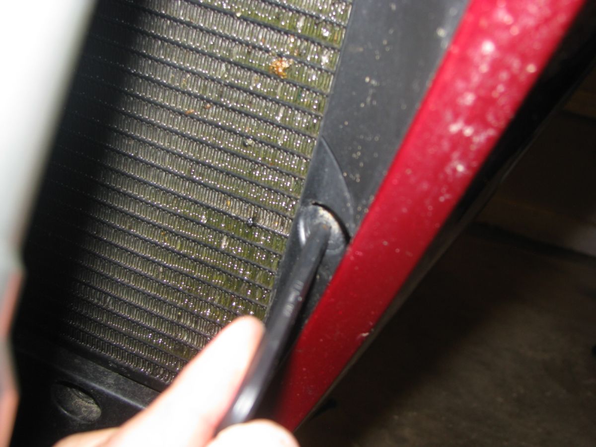
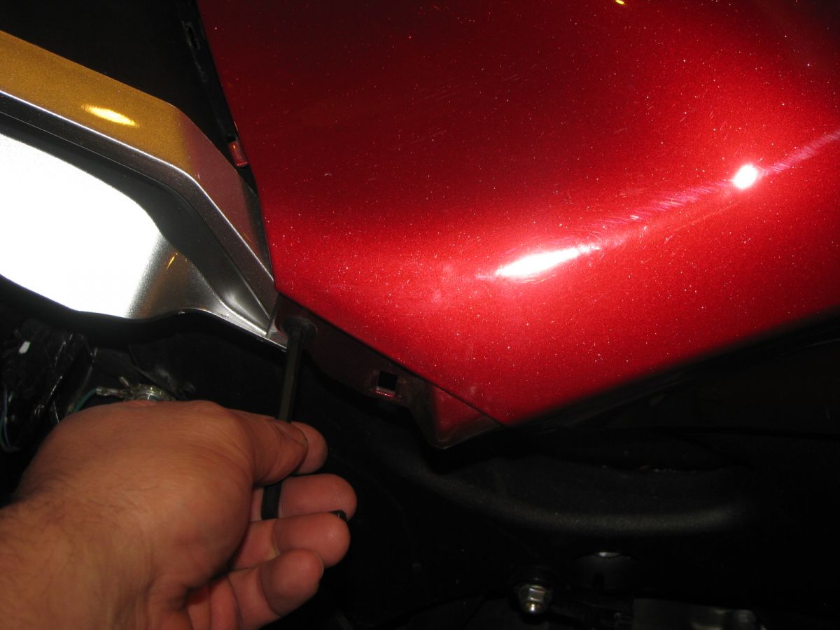
Removing lower right side fairing 5mm bolt bolts to the radiator skirt
removing trim piece fastener from the left side tank cover push in the cap and remove the fastner
removing the rear 5mm bolt on the left side tank cover
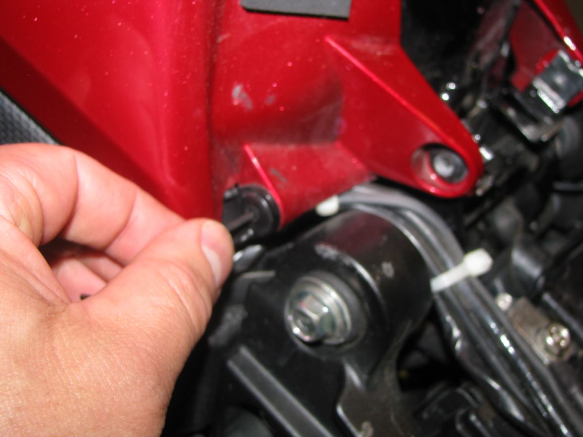
removing right tank cover front fastner push in the cap and pull out the fastner
Pulling out the left fairing from the left tank cover the snap in connector was removed first and a built in plastic dowel guides into a hole in the tank cover to line up in one smooth shape
Removing 5mm bolt from rear of the left side fairing
Removing upper 5mm bolt there is also a phillips head screw below that you do not need to remove
removing trim piece fastener from the left side tank cover push in the cap and remove the fastner
removing the rear 5mm bolt on the left side tank cover
removing right tank cover front fastner push in the cap and pull out the fastner
Pulling out the left fairing from the left tank cover the snap in connector was removed first and a built in plastic dowel guides into a hole in the tank cover to line up in one smooth shape
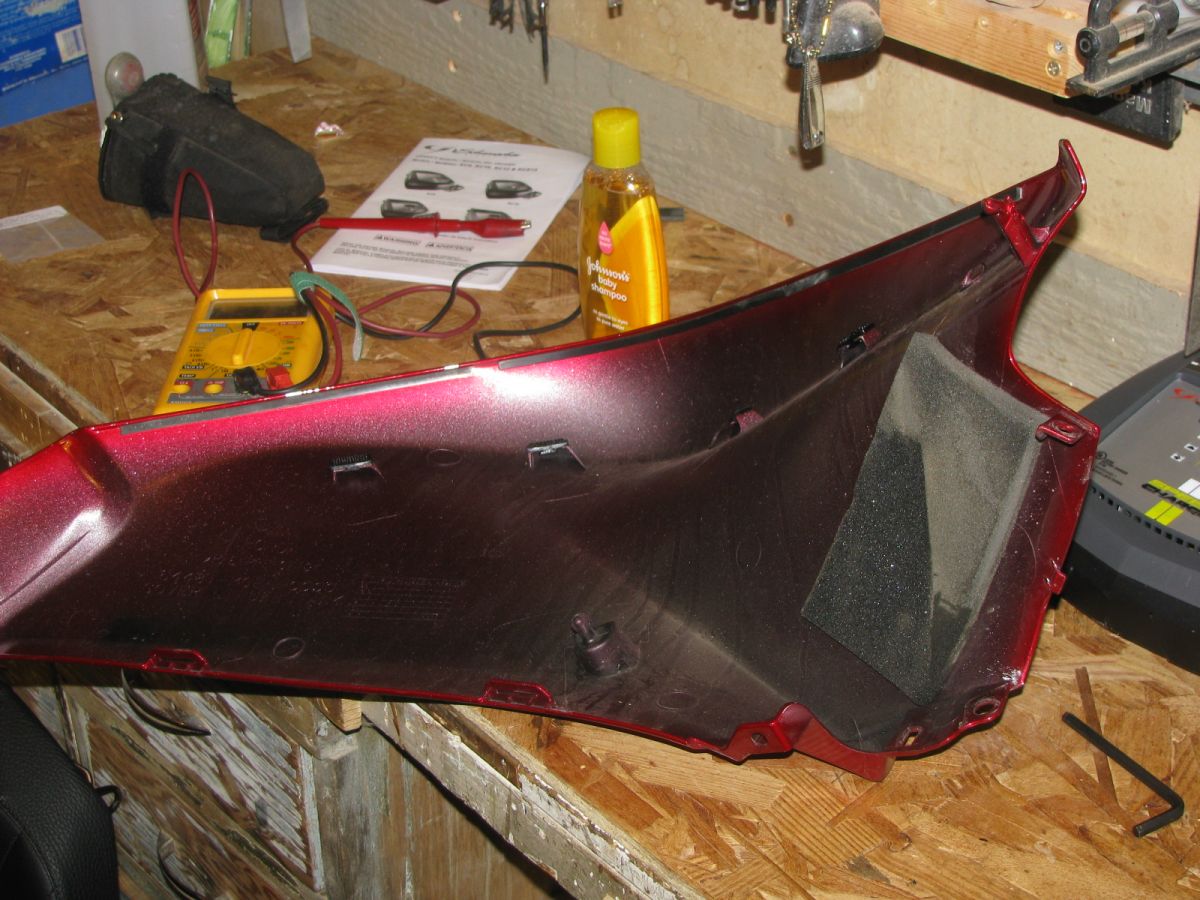
Right side fairing removed
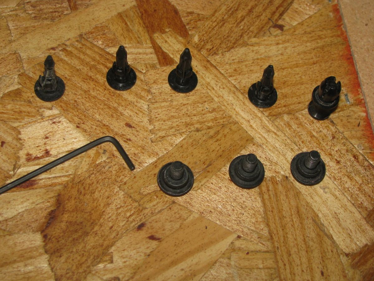
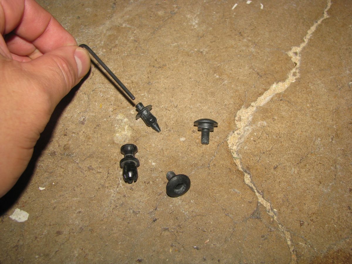
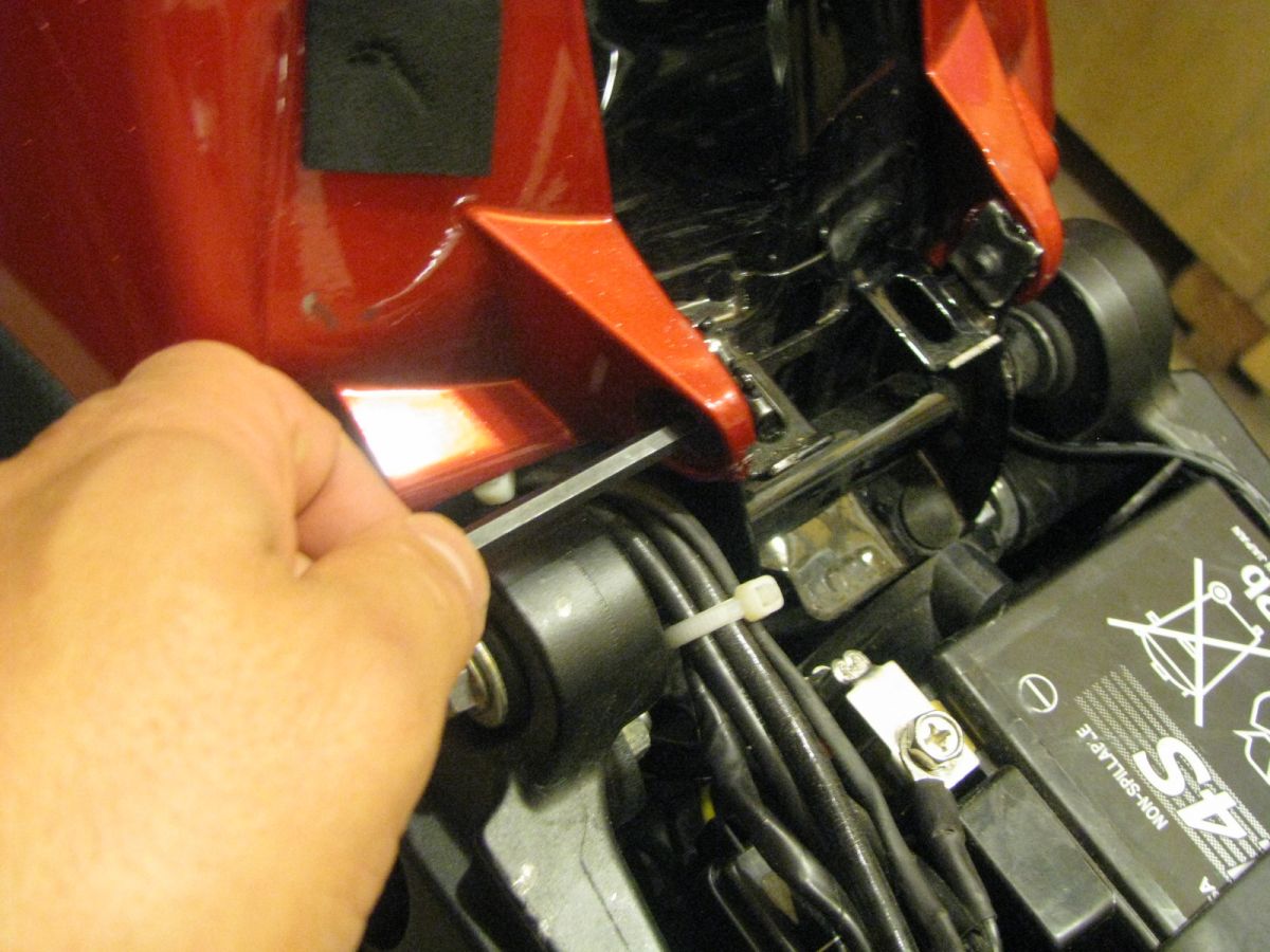
Fairing fasteners 4 small push in plastic fastners 3 5mm bolts and one larger snap in fastner with a pull out handle I used the small hex tool to push in the caps to get out the smaller plastic fasteners
removeing the 5mm bolt from the front of the tank cover
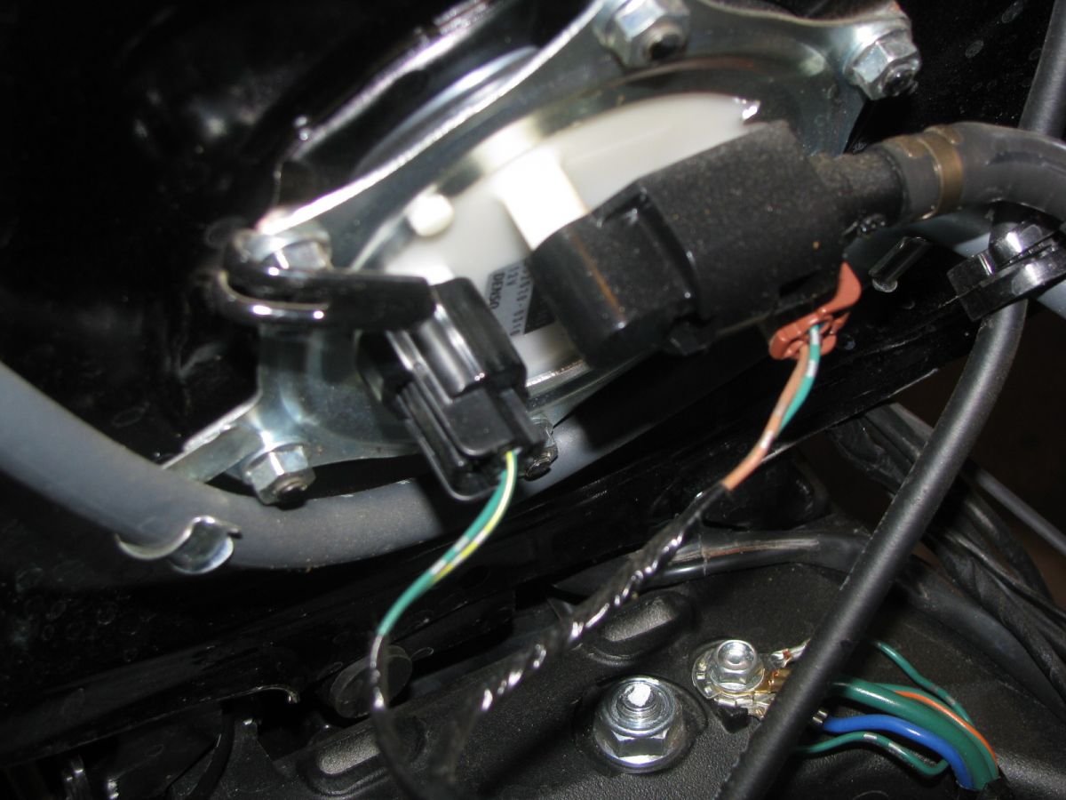
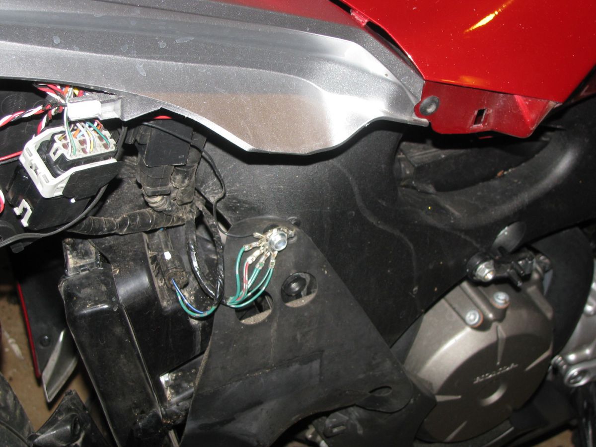
Fuel pump new style fuel feed connections level sensor and fuel pump power connectors no longer has a fuel return hose just a vent hose and an over fill drain hose for 3 hoses instead of four like on older models
5mm bolt hole to the right bottom
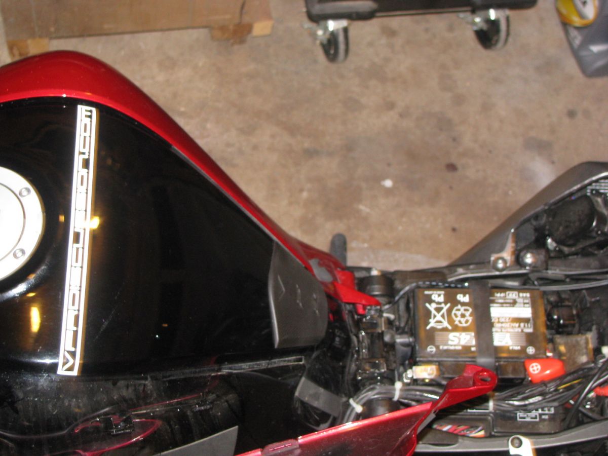
Pulling off the tank cover removed the four fastners pulled out the plugs and now snapping off the heavy duty velcro style fasteners
Inside a tank cover uses heavy duty velcro snap on fastener two guided plug into grommets two 5mm bolts and two small plastic snap in fasteners
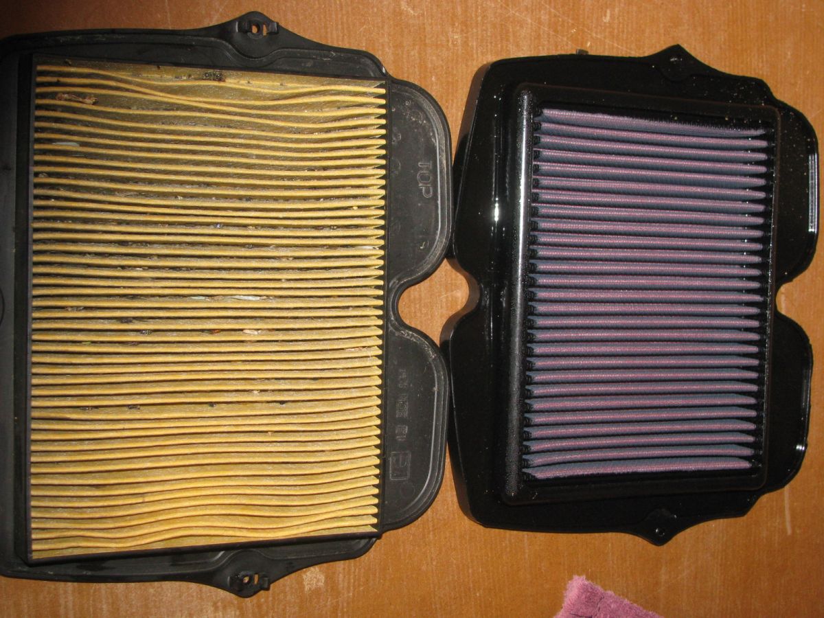
9000 mile oem unit not too bad but full of dead bugs
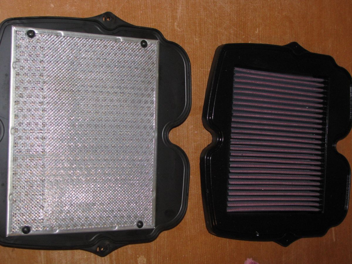
OEM filter compared next to KandN the OEM has a screen and a grate behind that
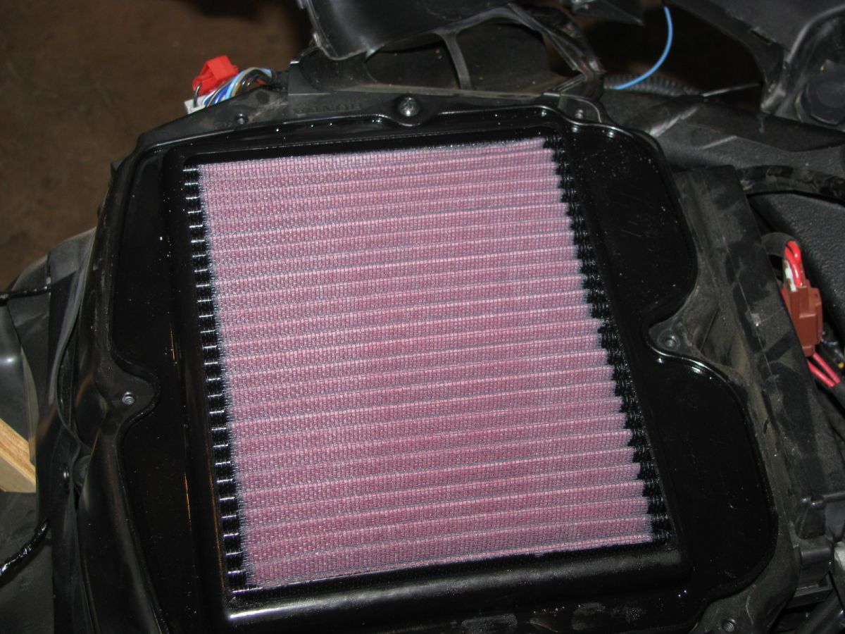
vfr1200 kn filter pleated protusion fits faceing upward
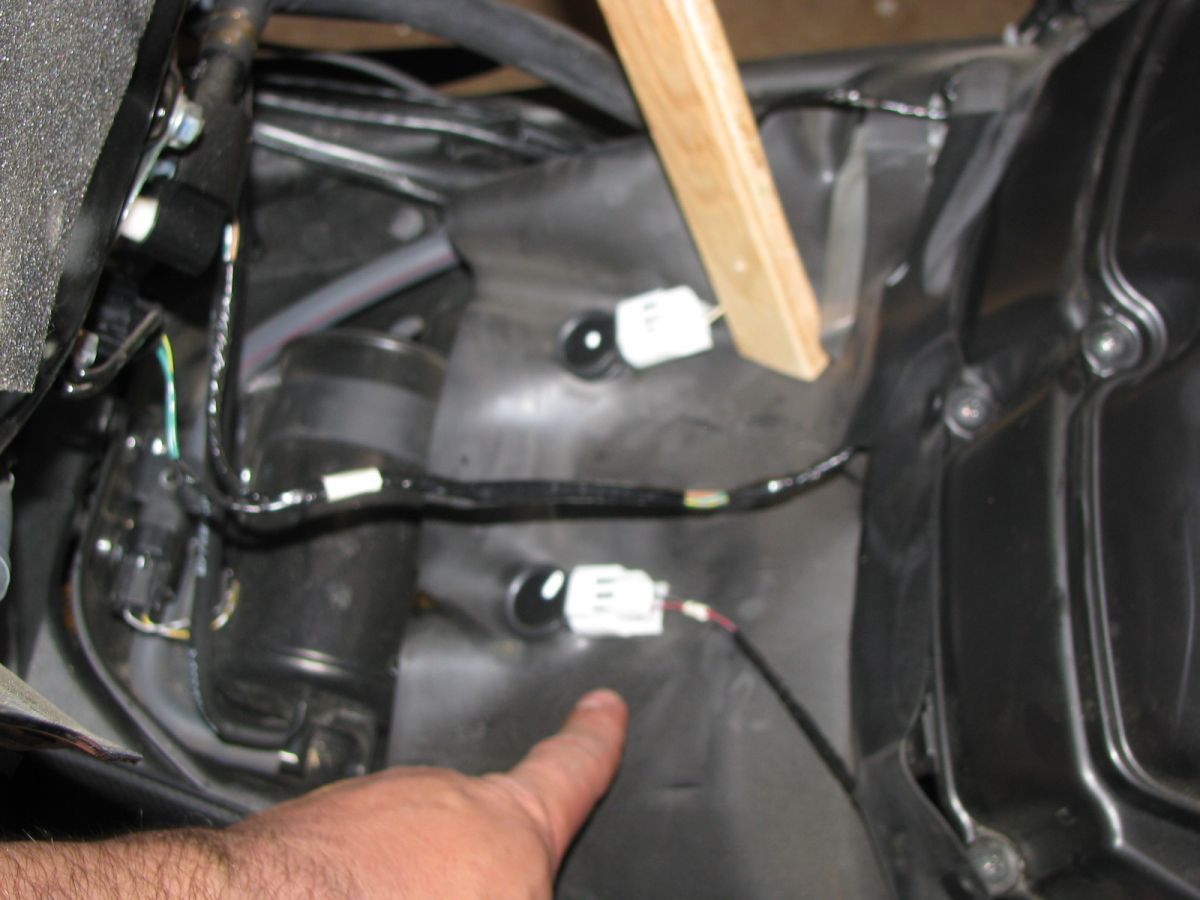
Airbox Temperature Sensor same unit used on my old 98
Coil on plugs newer coil technology no loss of voltage with coil on plug
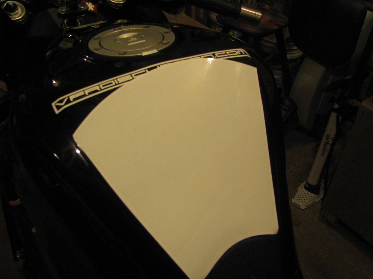
Tank Slapper Lower Tank Piece the 3m film needed to be cut to clear the vfrd graphics, they will not seal around other stickers so close to the edge.
Tank Slapper Front Tank Piece Dry fitting and cutting to clear vfrd graphics
EDIT adding snaps of the service manual taken by my phone (scanner not working at the moment)
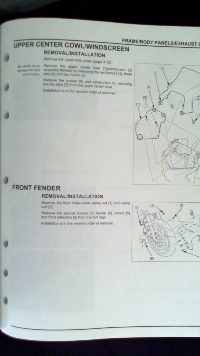
2011 05 08 18 54 02 889
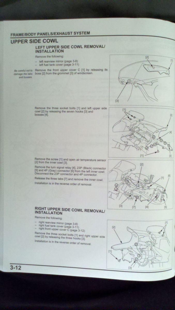
2011 05 08 18 53 52 992
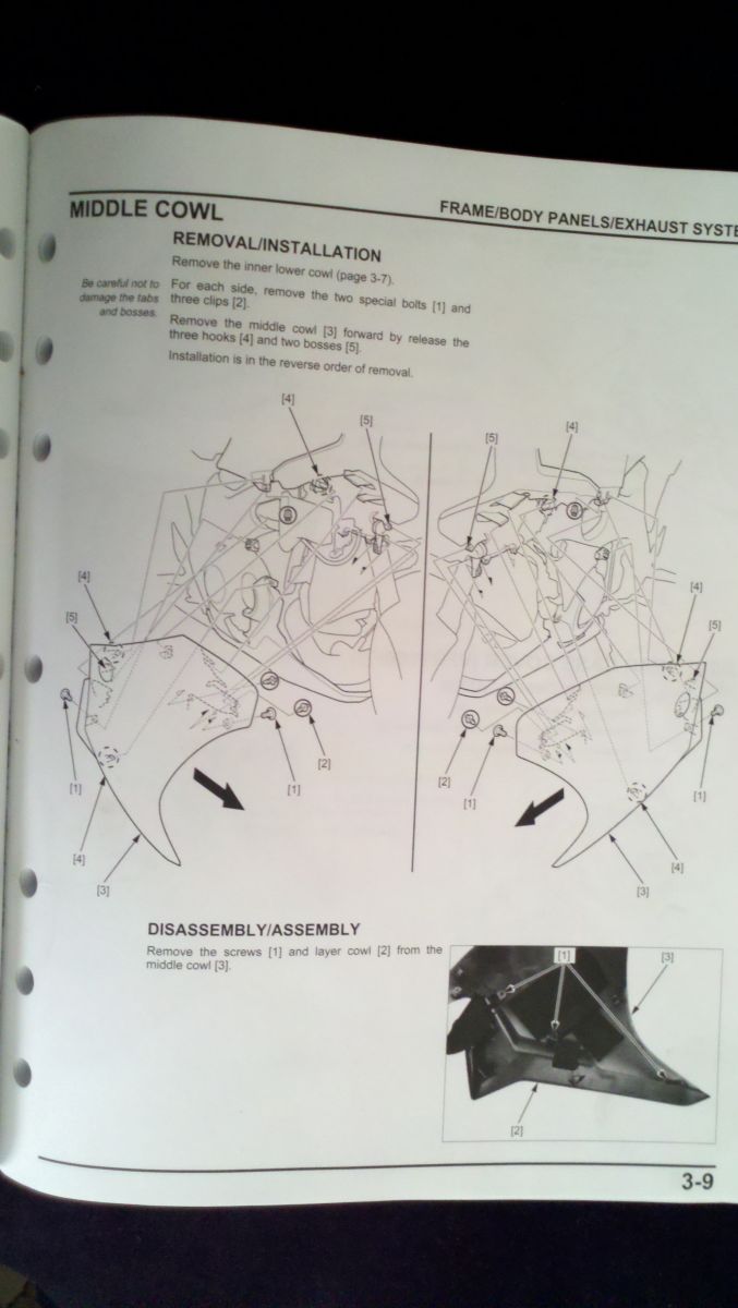
2011 05 08 18 53 28 663
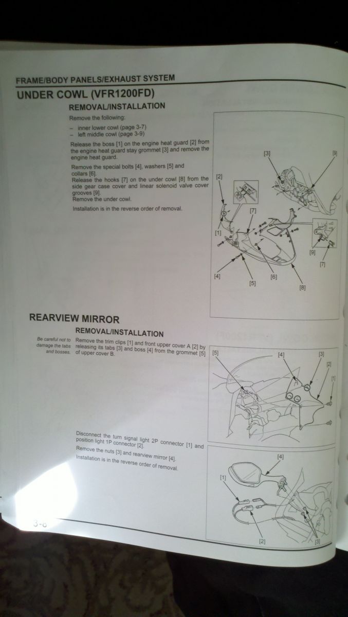
2011 05 08 18 53 19 918
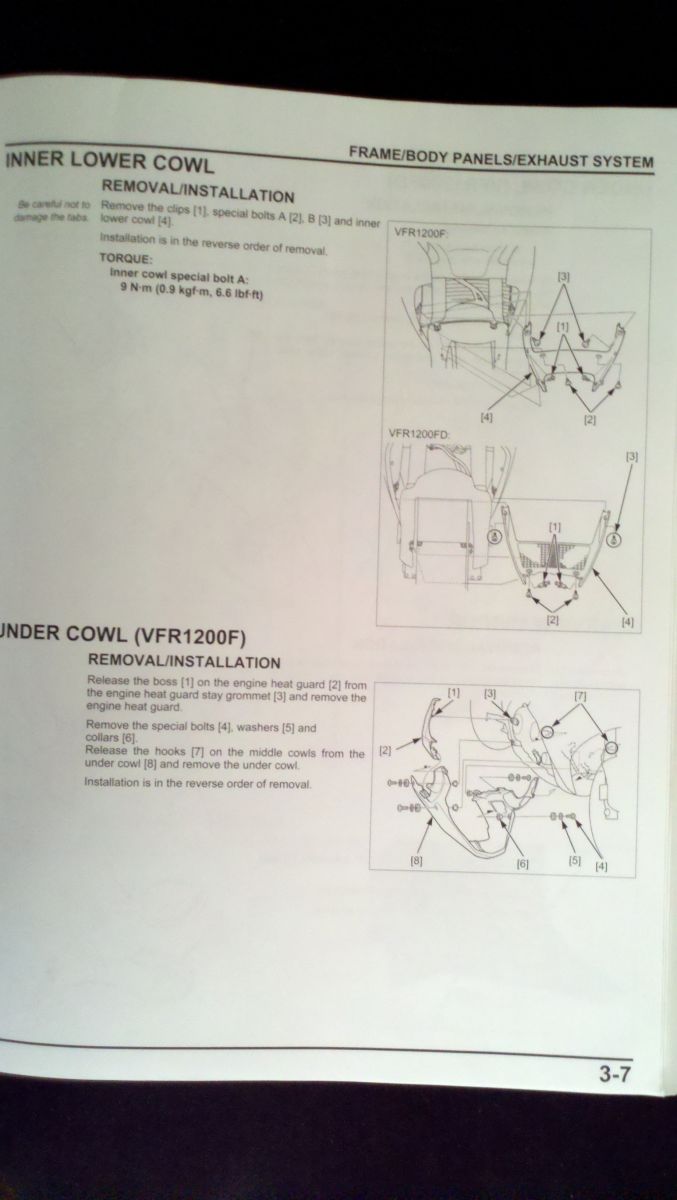
2011 05 08 18 53 08 936
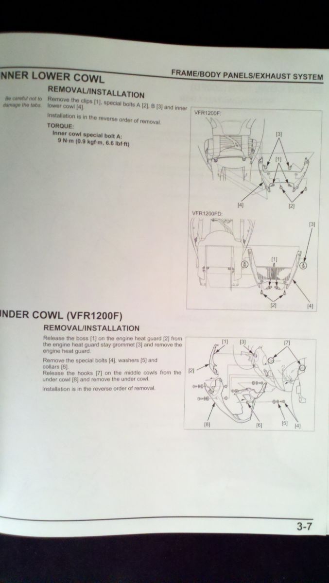
2011 05 08 18 52 32 746
-
The no hole saw thing can be worked around, I like Radars solution he has a couple of bobbins you insert into the frame, drill pilot holes from the opposite side through the bobbins for perfect alignment - one side at a time. then place a long rod through the bobbins and attach the hole saw to the rod and finish the holes off with the rod as your guide no mess no mistakes. I dont like the mushroom designs though with the skinny end bolted to the frame. I broke off two of them like that snapped right off. The non taperd design is much better, with a wider base to spread the load onto the frame, they dont snap so easy and slide more.
-
The center stand was the 1st accessory I bought for my 1200F last June, installing it was a breeze.
Making us pay extra for something {The Center Stand} we used to throw away is a rotten thing for Honda to do. :mad:
I dont know if they did that as a so called "rotten thing to do", it was said in another thread that since the bike has no chain there is no need for a center stand since lubing a chain is no longer nessisary. I tend to agree with that, and well many vfr riders removed it as you stated so why put somthing on like that on a bike that many riders dont want and no longer need? I need one cause I change my own tires and taking off the rear tire and even the front having the center stand on makes that possible.
-
 1
1
-
-
You mods should just go ahead and remove the reply w/ quote button from Skuuters posts :biggrin:
Just Kiddin ya Skuut, love yer posts man
working on a half eaten food picture button!
-
Yes if you click the add reply button at the very top it will not quote any posts, if you click reply to post it will quote the post, all of it, there is an opening tag for quotes and a closing tag with a slash in it, the slash must be there to close the tags.
[quote]this is what gets quoted between the tags[/quote]
-
Oh man I wish you had taken pictures along the way and posted it as a project I would have loved to see how you developed it along the way. That is awsome! I hope it works and you can ride it safely.
-
You cant even buy the mercury type manometer anymore - illegal in most states now. Along with lead wheel wieghts also now illegal. I have my pos mecury motion pro tool. I lost one of the damper inserts so one sight glass goes nuts while the others are calmer. I suppose you can make a new one out of pressure gauges, or staple up 4 clear tubes up to a long board of plywood - a few old carb jets and you got a homemade manometer.
-
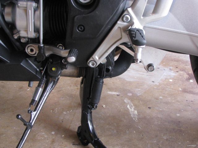
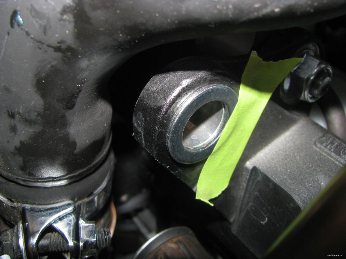
Center stand installed and lifting the bike up
These are the steps to installing an oem centerstand for a VFR1200F Part Number 08M50-MGE-100 This retails for around $200 delivered, I got mine from ServiceHonda.com. Before even attempting to do this MAKE SURE THE BIKE HAS COOLED OFF you will be working around the headers and you will burn yourself if its hot!
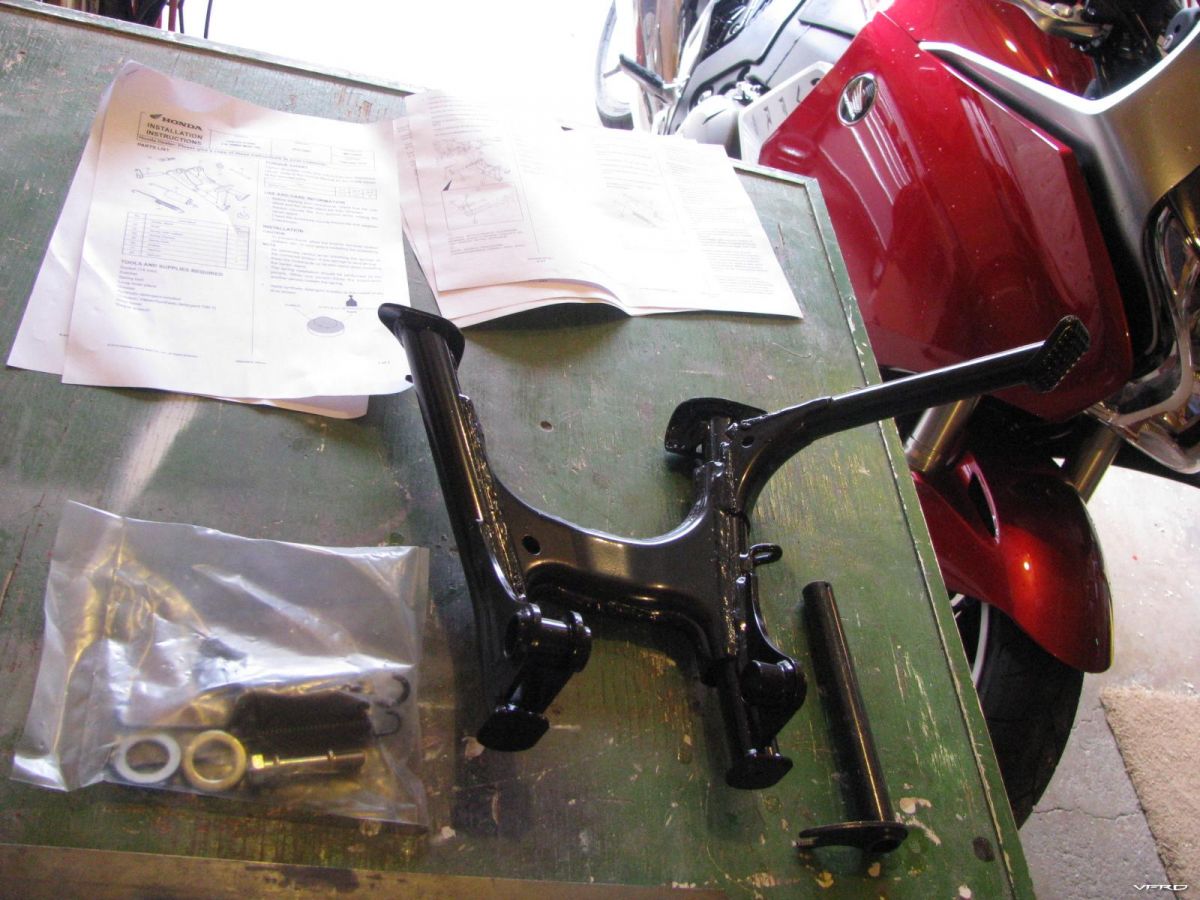
Centerstand parts and instructions
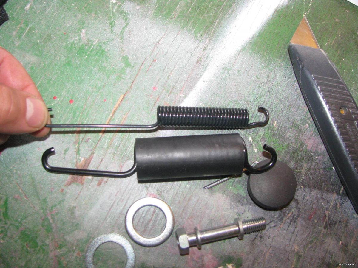
Inner and outter springs main spring and a safety spring that fits inside
Should the main spring break the smaller saftey spring inside will keep the centerstand up so that the centerstand does not fall during riding causing an accident
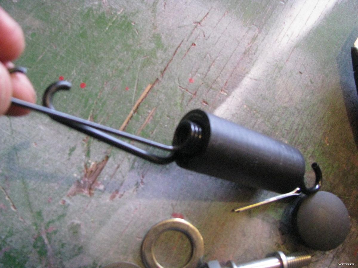
Bump pad wet with soapy water to install inside the hole in the stand
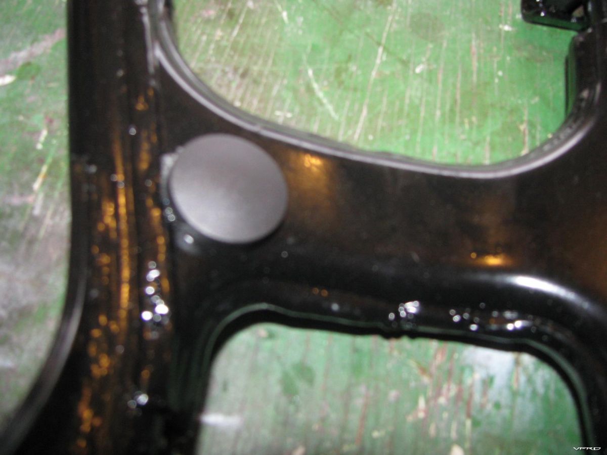
Twist and push on the bump pad until the pad seats itself inside the hole
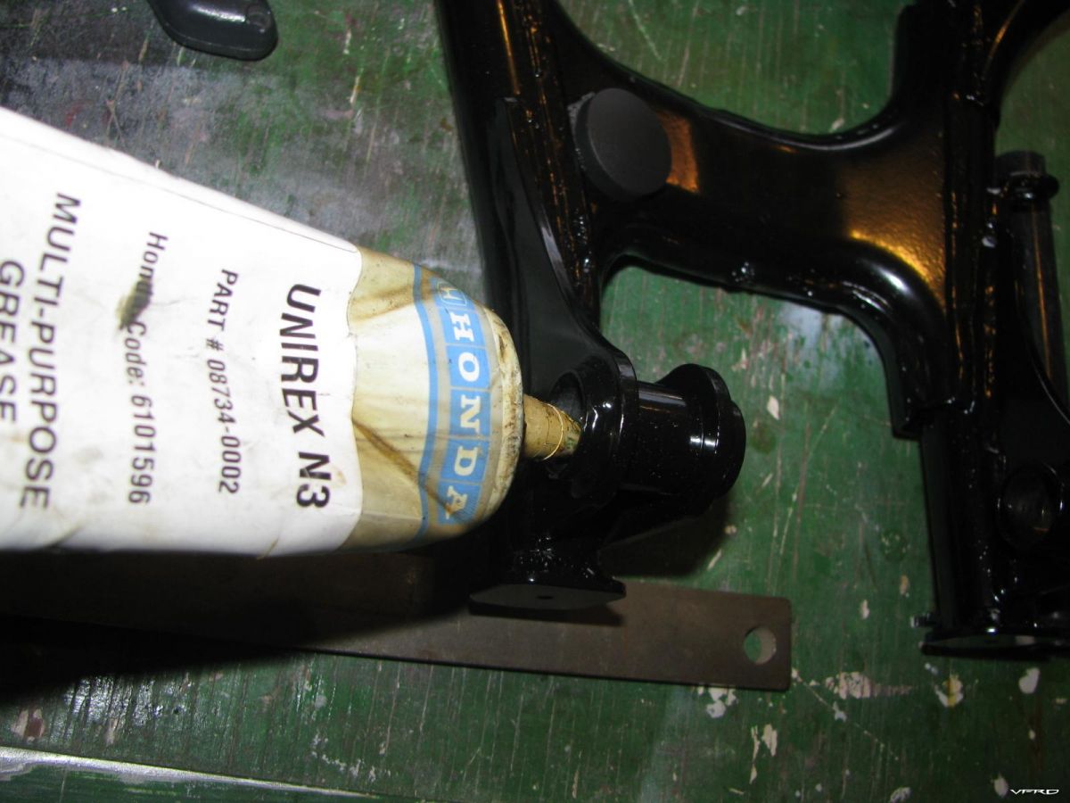
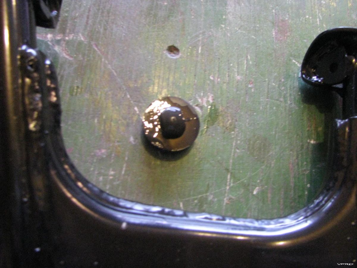
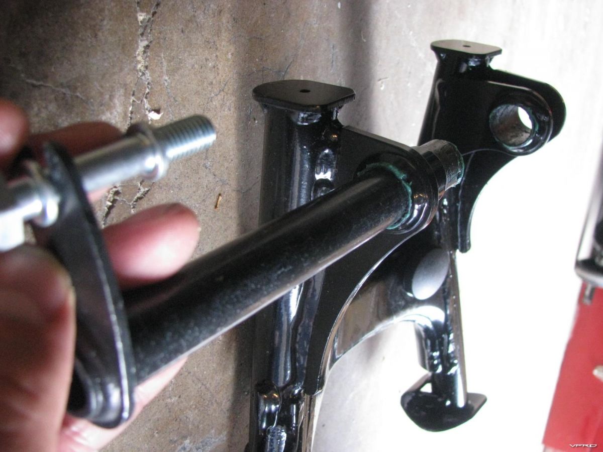
Grease the post holes
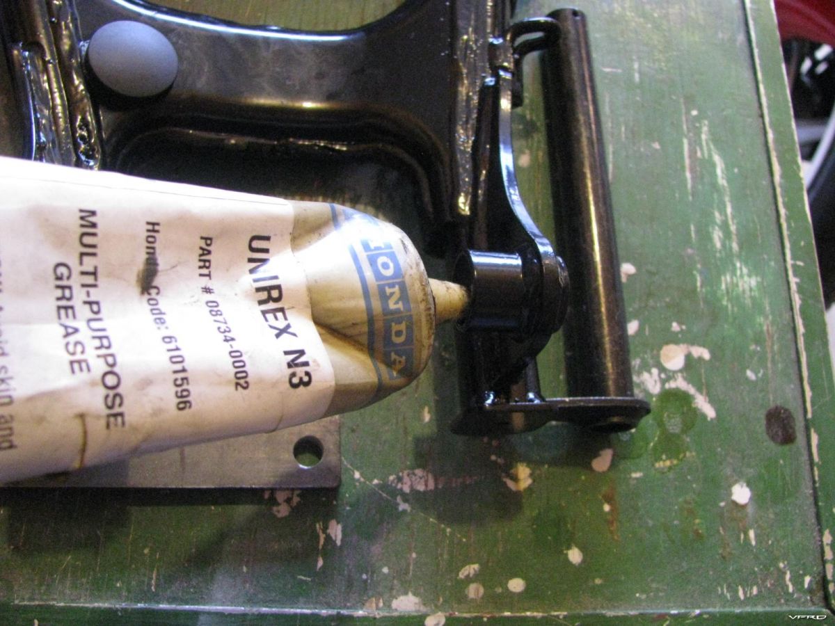
Grease the other post hole
This is where you will install the center stand post goes inside that large hole and the spring hook in the upper smaller threaded hole
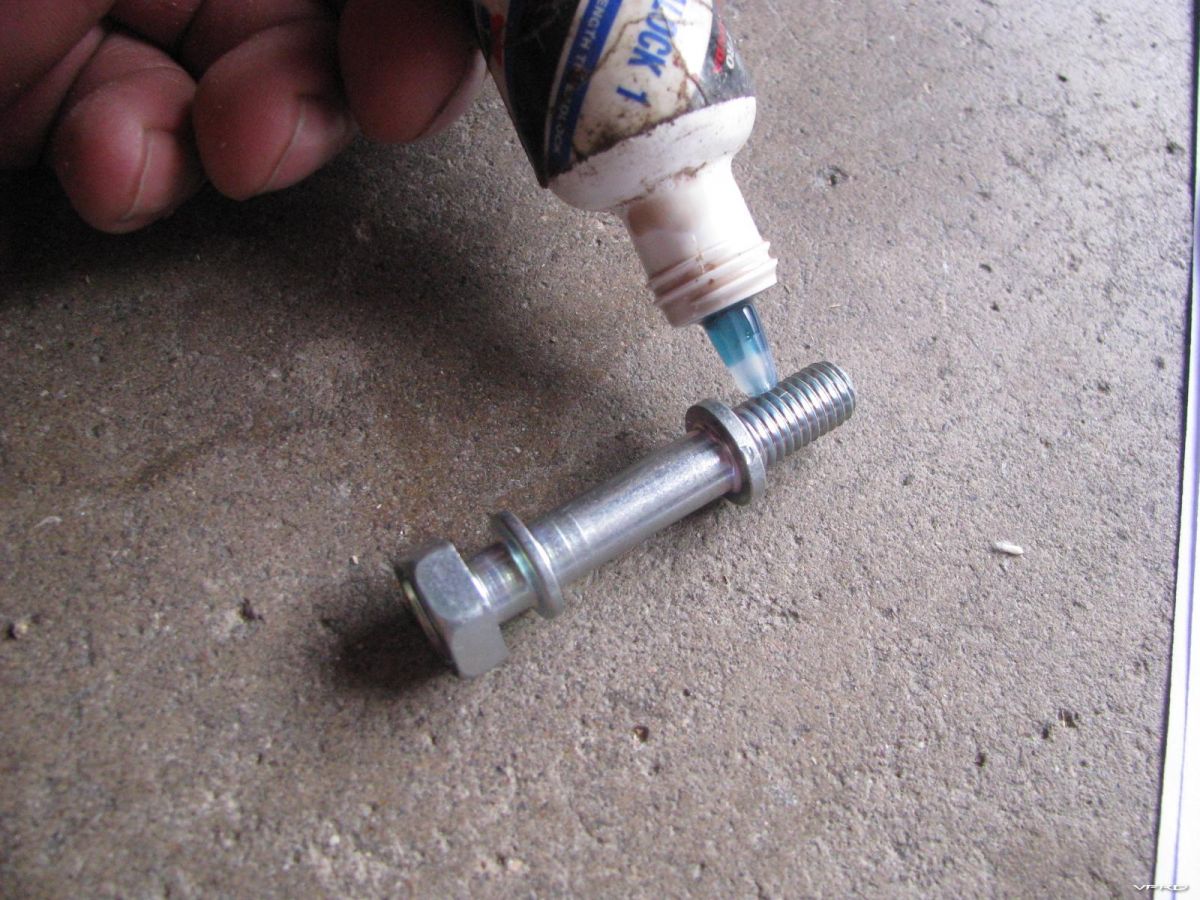
I used Honda thread lock on the spring hook bolt I dont want it falling out
The bolt is a 14mm bolt and the torque spec is 16 foot/lbs
Dry fit This is the basic layout of the centerstand mechanism
Here I am trying to install 1 of 2 washers on the right side washer 1 goes inside the right stand post hole 2 on the outside of same post hole
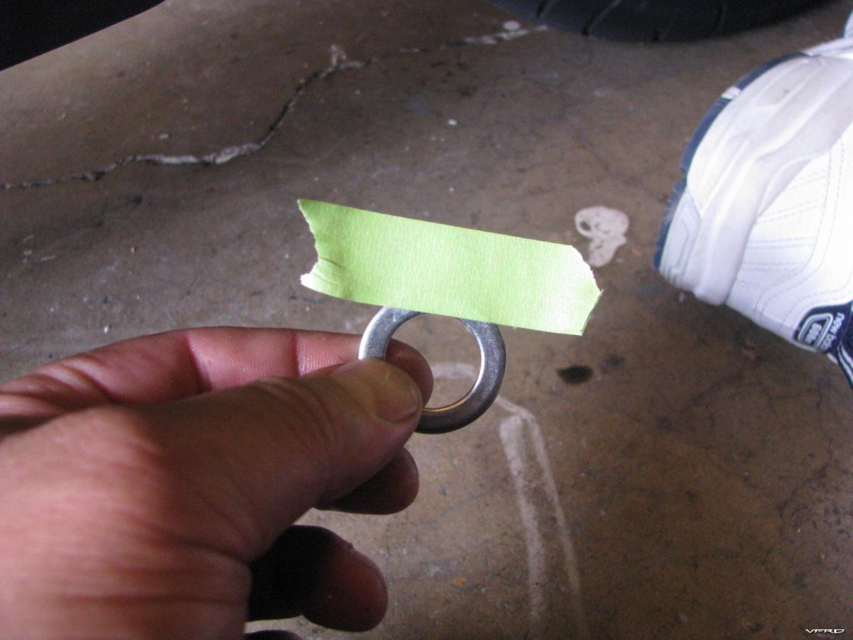
I had difficulty holding the washer in place so I taped it in place with masking tape
washer 1 taped into place
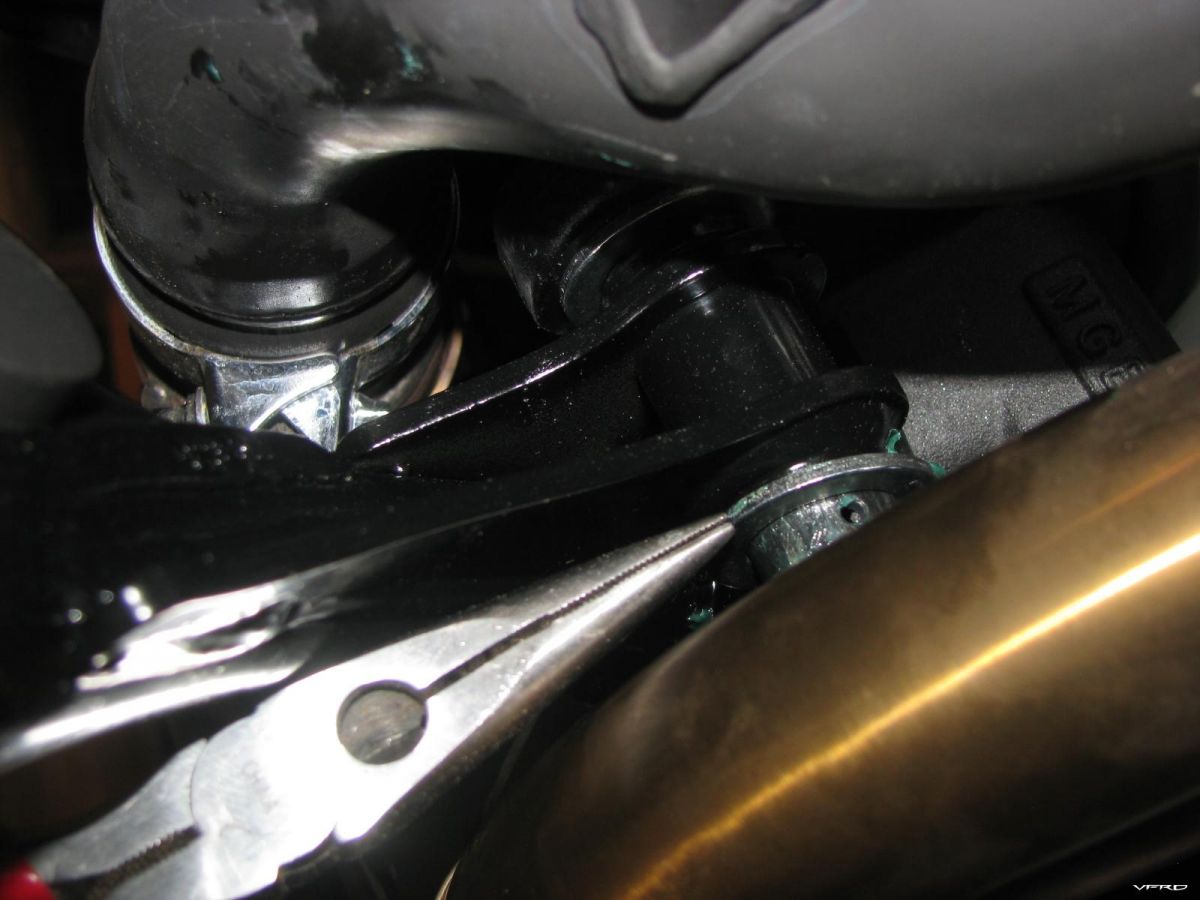
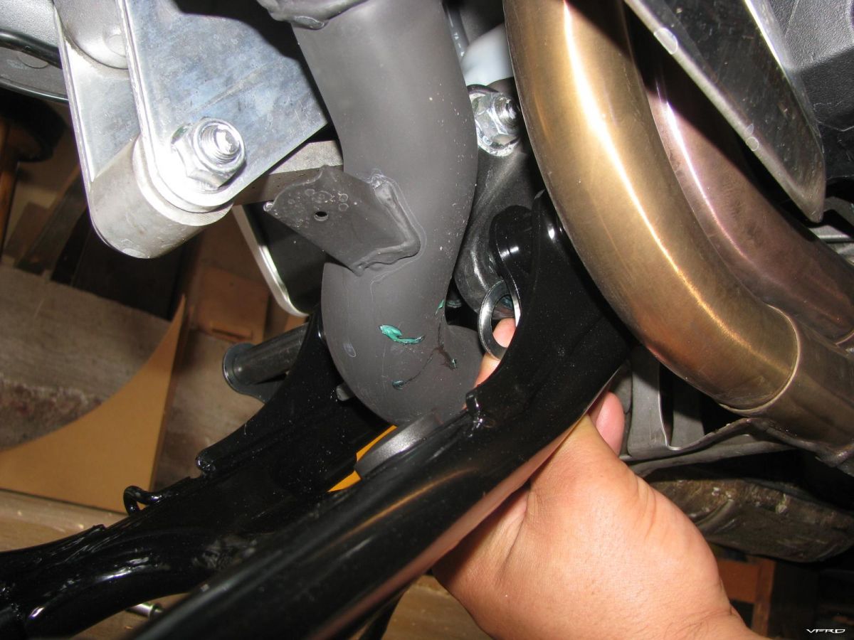
I slid the post into the post holes fitting washer #2 was also a chore not much room with the headers there
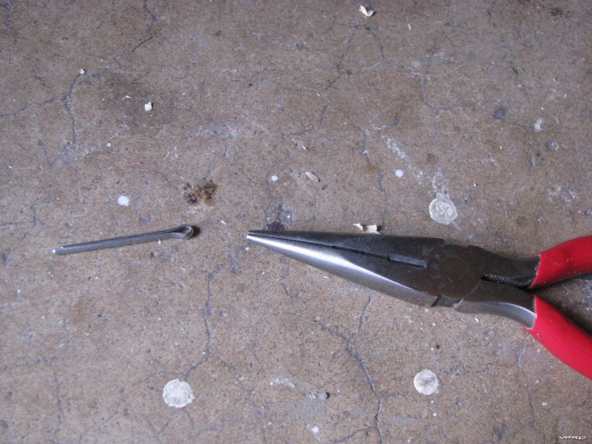
side the cotter pin into the hole in the post right side fingers or use a needle nose
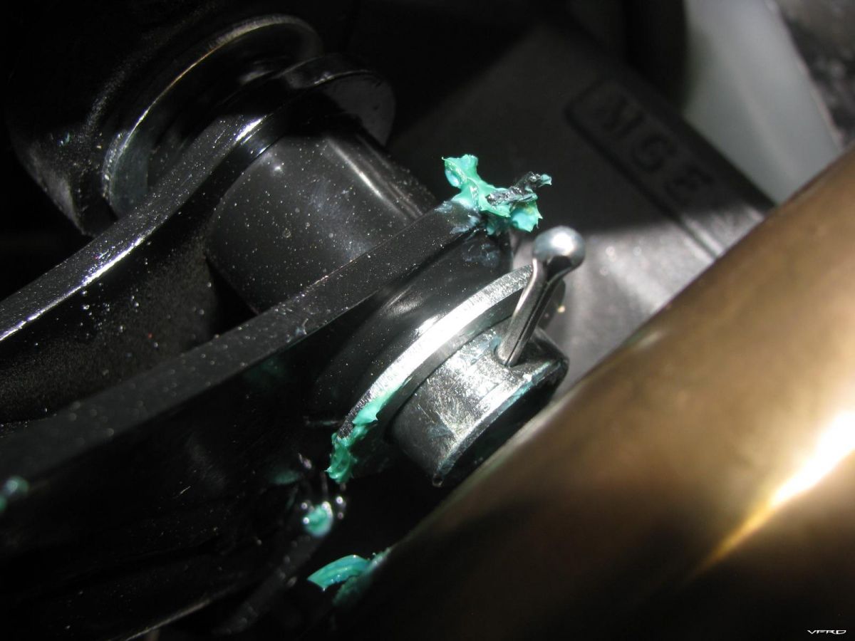
cotter pin goes here right side
spreading out the cotter pin ends is difficult to reach a flat head screw driver did the job from the front on the right side of the bike
installing the springs I used an old spring installer my Grandpa had for drum brakes - instructions call for two persons to install the springs
The safety spring did not go on the first time needle nose pliers for that
-
5
-
 1
1
-
-
I was in Oklahoma with the new vfr1200 wondering what I was going to do with my gps, the tank bolts are different and I could not mount the ram ball there. Gary looks at it, pulls out a half inch pipe and sticks it in the steering column and its snug and he goes to work cutting welding and drilling me a custom gps mount, even painted it. We used tape to get it tight in the hole and he welded a nub on the side to make it stick up an 1 1/2 from the stem.
Gswanson - Fabricator GPS vfr1200 stem mount cut - welded - drilled - deburred - painted
I got it home and the tape had held for the most part but the gps would swing out side to side a bit so I went over to a local bike shop and asked if they had an old steering column - man said steering columns are too thick but he had a bolt and wedge for mounting a triatholon bar that was smaller diameter and he pulls out the perfect size wedge and bolt! Perfect $7 and I was home modifing Garys mount. Drilled a hole in the top and a 1/2 hole in the ram ball to fit over the hex bolt and it worked. Tightened up the bolt till the wedge stuck in nicely, I cut some slits in the pipe to let it expand. wow it works great!
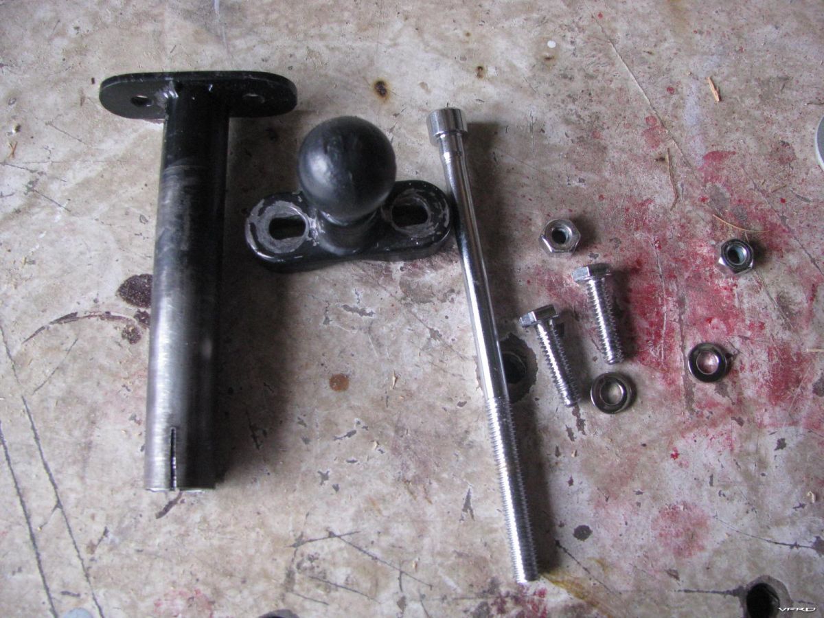
Gswansons Steering stem gps mount Gary welded a 1/2 metal tube to some flat stock then drilled holes shaped and painted the unit welded a nub on the side to make it sit up.
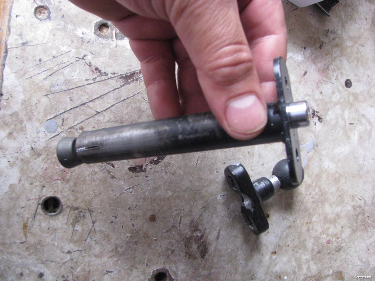
GPS Mount I modified it by cutting a slit in the side and I bought a bolt and wedge from a bicycle shop for a triathalon handlebar drilled a hole in the top of the mount for the hex bolt
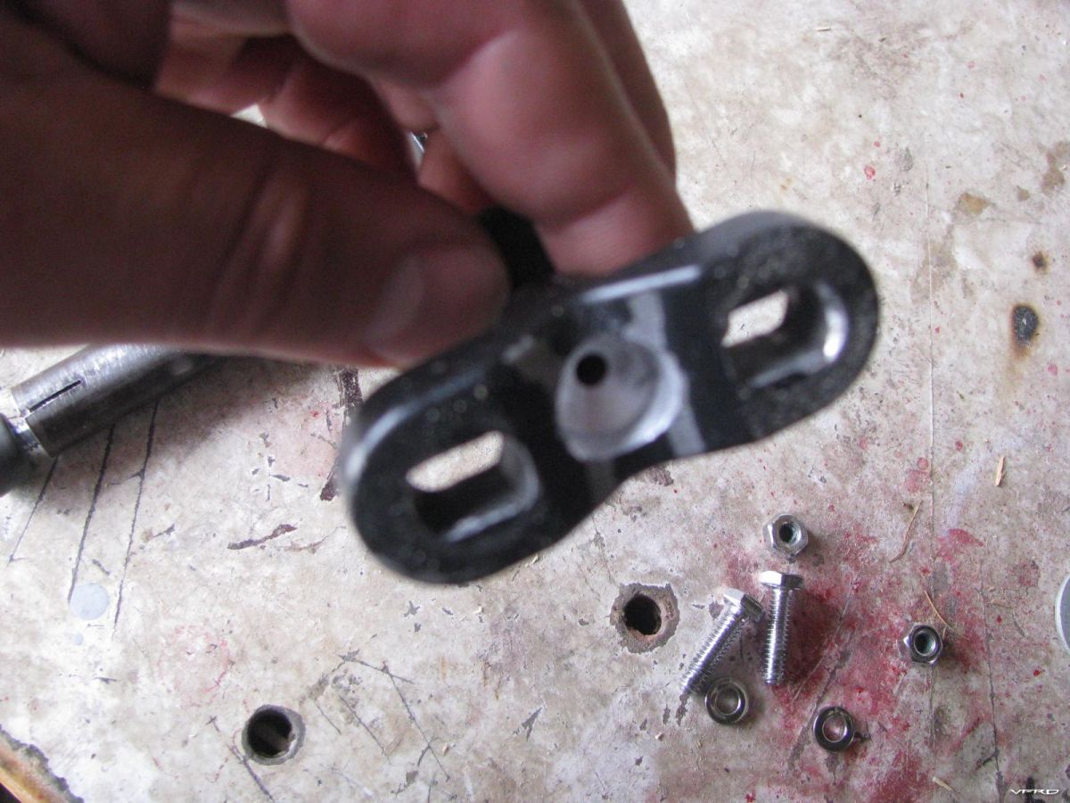
Ram mount ball I had to drill out a half inch hole to make room for the hex bolt head to bolt the ram to the gps mount
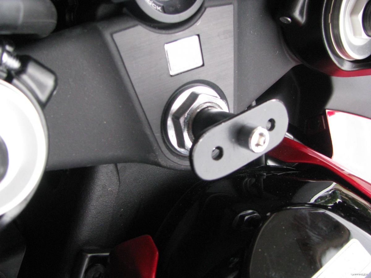
Slide the mount down the head tube pull up on the hex bolt and thread the wedge til it gets tight
-
I liked this post, I featured it. Are you at all concerened about the bubble dryer placement being in a postion to get crushed and perhaps catch fire if the bike should crash on it?
-
Hang on a second - what vacuum line is your MAP sensor connected to while you're doing the adjustment? The MAP sensor connects to a 5-way joint, and you remove all four feeds from that joint to hook into the balancer/manometer.
Ok I quoted the wrong part of your orginal post, the part where you hooked up the map sensor back up to a different line..ala not by the book as it were. I have to admit there are parts of the vtec that are easier to do than the 5th gen but hooking up the manometer is not one of them. I like how you just equalize them rather then set one at such and such pressure then drop it for the next two like the 5th gen, I always ignored that anyway.
I was more tempted just to get the manometer close to equal then tweak them till the bike ran smoother and idled best, that seems more important than what the insturment says in the final conclusion of the work. You can hear and feel a smoother idle as you tweek the SV's seem to me on my 5th gen the more I went by spec the worse the lump got on the idle I was better off equalizing them and then tweeking here and there till it was idling smoothest.
-
Does one really need an electronic tach...?? You can't just use the one on the console??
I'm hoping to do this maintenance soon.. together with new thermostat, new stator (2nd one fried) and new chain and sprocket kit...
No the tach on the dash is not accurate to 300rmp
-
You CANNOT sync the starter valves when the MAP sensor is connected and working!
NO - If you do the procedure as laid out in the manual you will have no trouble adjusting idle. If the manometer balance is off for the 4 starter valves when you first hook it up you just set them equal to the non adjustable valve, the idle speed will fluctuate as you do this YES. The basic balance will be preserved as long as you dont go banging around too much. The problem lies with trying to adjust balance and idle speed at the same time, if your trying to get the idle set at the same time your adjusting each starter vavle indivdually of course it will be difficult.
SO Start with the recommended idle speed, next adjust the vavles till they balance, THEN reset the idle again and your done. They wont go out of balance after you adjust the idle unless you are trying to do both at the same time. Do one thing at a time here, so yes the idle speed will change when your adjusting each of the valves to balance, leave the idle screw alone till you get them in balance and ignore the wild changes in idle speed, once they are balanced then adjust the idle one last time to the correct speed.
-
2
-
-
I had my bike sitting with no fuel for over a month, sused out the fi codes and fixed them then came to the conclusion that my fuel pressure regulator was bad. This requied me to remove the fuel rail. So out came the fuel injectors and they were nasty. I cleaned the whole throttle body with a spray on carb cleaner, sprayed the inside of the injectors and let them soak in sea foam overnight. Here is the rub. The seals were 12 years old and the manual says to replace the seals whenever you remove the injectors. I did notice on the 98 vfr the injectors sit inside a cone shaped oriface inside the flat o shape seal - there is no way they are falling into the engine they would just get wedged inside that cone. ( I am sure by design )
Turns out the Injectors for my 98 are a common part for many cars too - I did some reseach and there are about 12 honda cars that use the same injector and seals. I found a replacement kit at Napa and did a side by side comparison - no difference. They have a more expensive brand that uses a superior oring too.
These are the same part numbers for my 1998 vfr
16472-PH7-003 OEM Honda Accord SEAL RING, INJECTOR (OTSUKA)16473-PD6-000 OEM Acura CUSHION RING, INJECTOR (OTSUKA)91301-PM7-003 Acura Fuel Injection Corp. Fuel Injector Seal Kit for Acura Integra 1.8 GS 4drNAPA REPLACEMENTS
Fuel Injector Seal KitProduct Line: Echlin Fuel SystemPart Number: CRB 212089Fuel Injector Seal KitProduct Line: AltromPart Number: ATM IK2903 -
I needed a bike size vat to stick my whole bike in, boy it was filthy!
-
If a bulb is blown its resistance is infinite high? How can low impedence give you a blown indication? Do you mean the opposite? They probably have a 470 ohm reisister in there. I have been changing these darned things out seems like twice a year now, LEDs and 100,000 hours sounds much better to me. IF THE FI LIGHT IS BLOWN how does the ECM deal with that, is this just speculation? Dont tell me the fi light comes on HEH

You are right - its the other way around...brain :beatdeadhorse: not thinking straight in the heat of excitement :cheerleader:
Just a speculation - let me know if it works for you
I could see the fi light error pulses comming in at a different pace, or issues with that perhaps? I will try it, they do match the impedence with the led bulbs to the OEM bulbs with a built in resister, its right there in the photo.
-
If a bulb is blown its resistance is infinite high? How can low impedence give you a blown indication? Do you mean the opposite? They probably have a 470 ohm reisister in there. I have been changing these darned things out seems like twice a year now, LEDs and 100,000 hours sounds much better to me. IF THE FI LIGHT IS BLOWN how does the ECM deal with that, is this just speculation? Dont tell me the fi light comes on HEH :cheerleader:
-
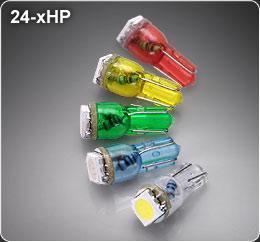
I ordered white LED replacements for my dash today, I dont care about changing the color I just wanted to save a few watts and help extend the life of my stator, ordered the mini ones too for the nuetral, highbeem, fi lights too, I ordered an extra of each type in case I get bad ones
6 | WLED-x4 LED bulb | $ 2.59 |
90 Degree White WLED-W4-x 1.00 - DASH BACKLIGHTING
----------------------------------------------------------------
3 | WLED-xHP High Power LED bulb | $ 4.95 |
Pure White WLED-WHP - TURN SIGNALS
----------------------------------------------------------------
5 | 24-xHP Wedge Base LED bulb | $ 2.49 |
White 24-WHP - FI, NUETRAL, OIL PRESSURE, HI BEAM indicators
----------------------------------------------------------------
-
I spent a good hour taking off the tires, valve stems, dust seals, bearing and brake discs on a pair of wheels I got on ebay. Drove over to spectrum powerder works and they are going to strip and powdercoat them white for me. good prices!
-
You will need that oil spacer since the vfr fork bottom bolt will not properly screw into the compression valve body without it. I have it in mine and I have the same setup.
-

An electric waterpump means the mech drive is no longer required, and saves some power (it all adds up). Also you can set it up to run on when you switch the motor off, which eliminates heat soak.
Saves power? Doesn't that power get absorbed by the motor yet again driving the stator to power the electric water pump? I could see if that microcontroller turned it off and on by demand?
-
1
-
-
Cheapass plastic hugger looks awful but it does the job, so I put stickers all over it cause who the hell cares. Then some gel pro grips that melted on my trip to Glacier NP and stuck to my gloves, the red soft part just dissassociated from the harder black rubber and stuck to my winter gloves when I used my heated grips. Spend the whole day at around 45 degrees it was freaking cold for September! I stopped at some gas station to warm up and my gloved peeled off the red part I was so disgusted!
-
So how much a difference did it make when you fired it up? - I got a carbon pipe I need to do this with. (Great photos and post.)
MD
I did not pack it as tightly as I should have, needed more glass packing. It sounded more throaty, still too loud - it was a D and D afterall. I ended up with a new Staintune the next season. I gave it to one of the wera guys on the forum for track use, it made good power.
Just thinkin' out loud here... But the steel wool, while helping prevent premature blowout of the packing, may also be blocking the absorption of sound?
E-Ticket
Staintunes are packed with nothing but stainless steel wool, they absorb sound, or actually the pockets of air do inside the wool. Stainless wool is just more resilent than fiberglass in terms of resistance to shock.
-
Stainless Steel wool is what you need - regular steel wool will just rust away in a day or two.
Front fairing removal how to and K&N install
in Maintenance Guides
Posted
I ran one on the old girl for 80,000 miles, they clog up faster then an oem but a wash and a fresh spray of K&N oil and they are good as new, garuanteed to fit or they will give you a new one. I broke one and they sent me another one free of charge - I trust the K&N from personal experience, they require maintence but then again so does the OEM or rather replacement or blowing it out.
@duchgixxer - step one is not required if you undo the snap in as shown. Of course if your changing the oil then by all means go for it, add 5 minutes