Stray
-
Posts
585 -
Joined
-
Last visited
-
Days Won
14
Content Type
Forums
Profiles
Gallery
Blogs
Downloads
Events
Everything posted by Stray
-
Oh, and I forgot to say the Honda S2000 guys are using the Blackbird injectors for their built car engines. Aaaaand, it turns out the Hyabusa injectors are exactly the same size and are also being used in built S2000 cars. Blackbird and Hyabusa injectors are apparently the same size but flow differently (I don’t know the numbers). Soooo, if Blackbird injectors fit the VFR then so do Hyabusa. Come on folks - give us some info!
-
Hello All, Looking to pick the brains of those who know more than me about 5th gen VFR800 injectors - what can I upgrade my single-hole OEMs with? Got the whole bike torn down for a massive project and thought I’d upgrade injectors while there. Just because. Nothing wrong with the stock 5th gen units but injector technology has improved since the early pioneering days of fuel injection. Here’s what I know and read about: 1. 5th gen injectors are same as early Honda CRV cars and have a single hole 2. 6th gen have 12 holes and same as early CBR1k (I think?) 3. Mohawk is running early Fireblade injectors (4 hole?) on his 5th gen (would love to know more about this, mate!) 4. Someone in this forum is running CBR1k injectors on their 5th gen 5. Rangerscott fitted 6th gen throttle bodies to his 5th gen and reports better MPG 7. MPG has improved quite a lot from 5-6-8th gen 8. Some early Honda CRV guys are running Blackbird injectors in their built cars but having to boost pressure (read about this a long time ago...) I’d love to be told there’s “X” injector with 12 holes that slots right into the 5th gen throttle bodies but doubt it’s that simple. What would you do in my shoes if you had the bike apart and the time to mess about with this? Would love to be able to use 8th gen (or 6th gen) units but don’t know what needs modifying to fit. Don’t mind hackzing at things to make them work. Open to all options and opinions. I could just leave it alone but kind of set on upgrading. Best, Stray
-
New 5th/6th/8th gen performance header now in production in USA
Stray replied to sfdownhill's topic in Exhaust Systems
PM received and responded - thank you! Your work on this is nothing short of amazing, SF. You boys pulled off the impossible and others have tried for decades - respect! I wanted an 8th gen system so bad I could taste it but personal circumstances changed right as I was about to get one. Luckily things have improved somewhat but JUST too late to get on the last production run. Turns out quite a few people who bought these didn’t fit them and have had changes in circumstances of their own. I’ll pick up one of these and save waiting for the next run. -
New 5th/6th/8th gen performance header now in production in USA
Stray replied to sfdownhill's topic in Exhaust Systems
Anyone got one of these headers they want to shift? Ideally the 8th gen version for front-facing rad but I’ll consider any. Based in England and happy to import if it’s not extortionate. Please PM! Best, Stray -
New 5th/6th/8th gen performance header now in production in USA
Stray replied to sfdownhill's topic in Exhaust Systems
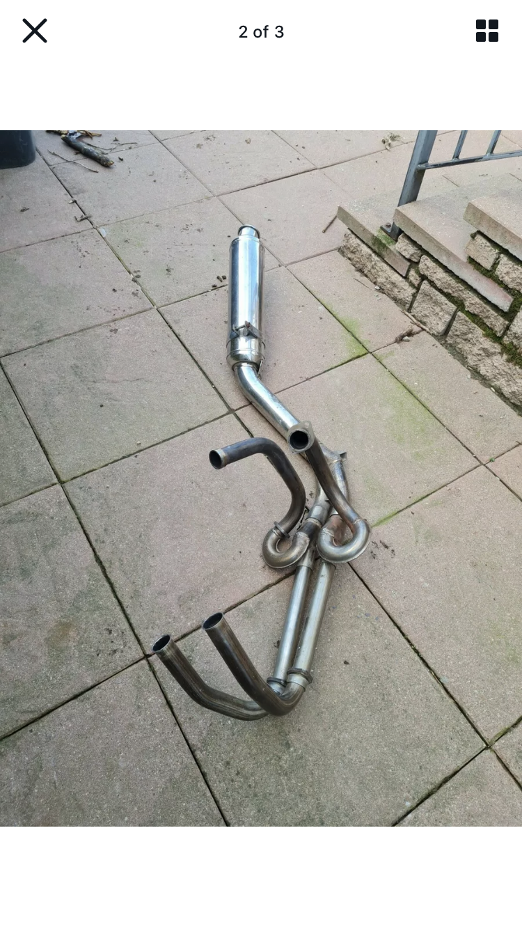
Slightly off topic, but I saw this interesting VFR750 header on eBay and thought I’d share: Note how it merges front and rear whilst giving the rear pipes a bit more length. I wonder if those loops interfere with the rider’s feet. Clever, me thinks!
-
New 5th/6th/8th gen performance header now in production in USA
Stray replied to sfdownhill's topic in Exhaust Systems
Docnut, does that setup cook your rear brake fluid? -
Hello All, Is there a list of engine bolts anywhere? I’m looking to replace all mine with Ti/SS/Al and would rather not pull them all out one-at-a-time for measuring. Will probably do the rest of the bike too (suspension, chassis and bodywork etc). Have seen a few “kits” for sale but they’re often marked up 400% compared to buying loose. On my other bikes I ended up having to compile (and publish) a comprehensive bolt list. Just hoping someone has already done it for the 5th Gen! Any advice welcome. Stray
-
New 5th/6th/8th gen performance header now in production in USA
Stray replied to sfdownhill's topic in Exhaust Systems
Thanks for getting back, Duc2V4. Shame to miss out but not the end of the world. Always wanted an 8th gen version but my financial position recovered just too late. -
New 5th/6th/8th gen performance header now in production in USA
Stray replied to sfdownhill's topic in Exhaust Systems
Chaps, is there going to be another run of these or are we done now? I fancy an 8th gen system. -
That’s a beauty!
-
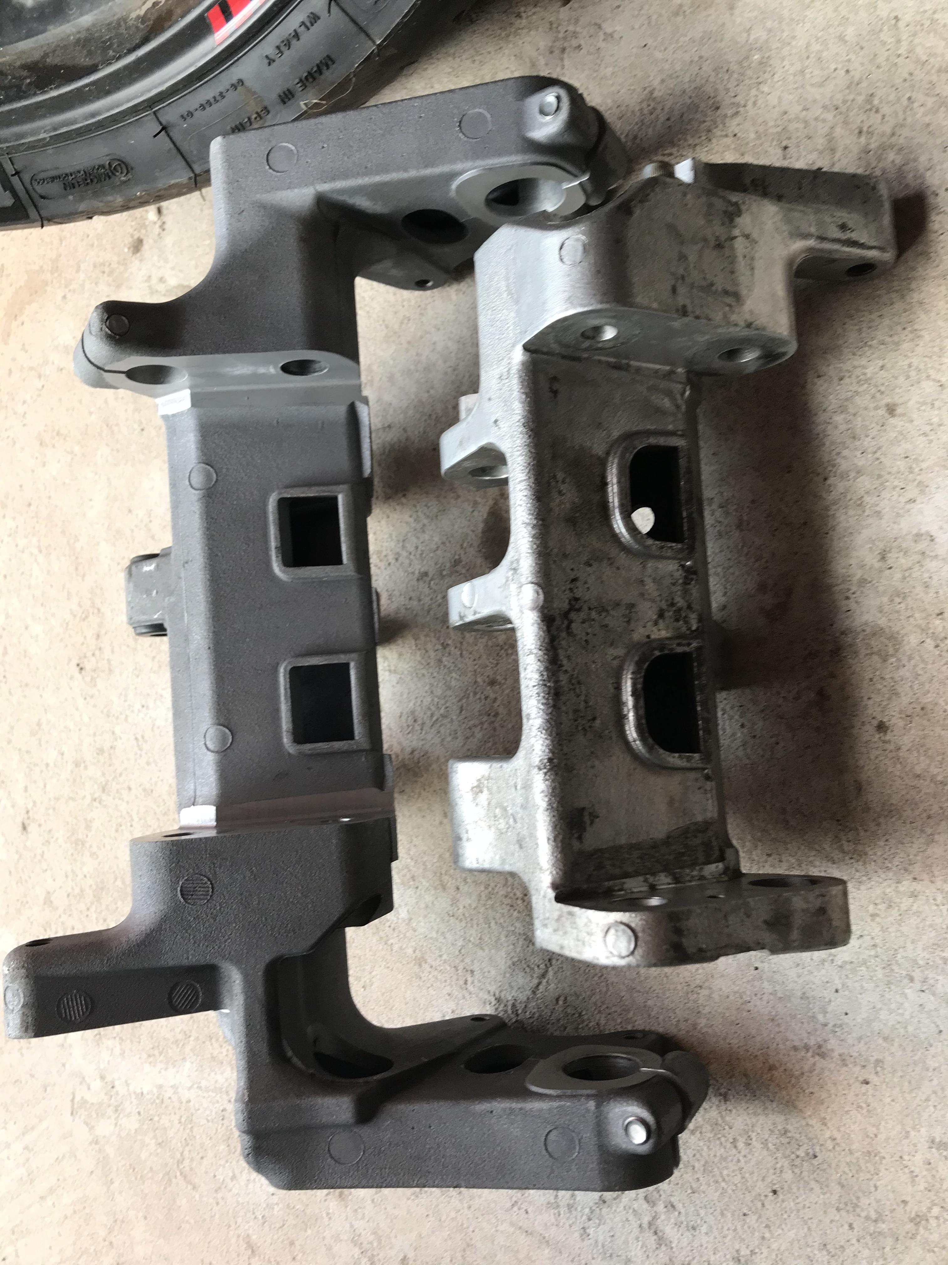
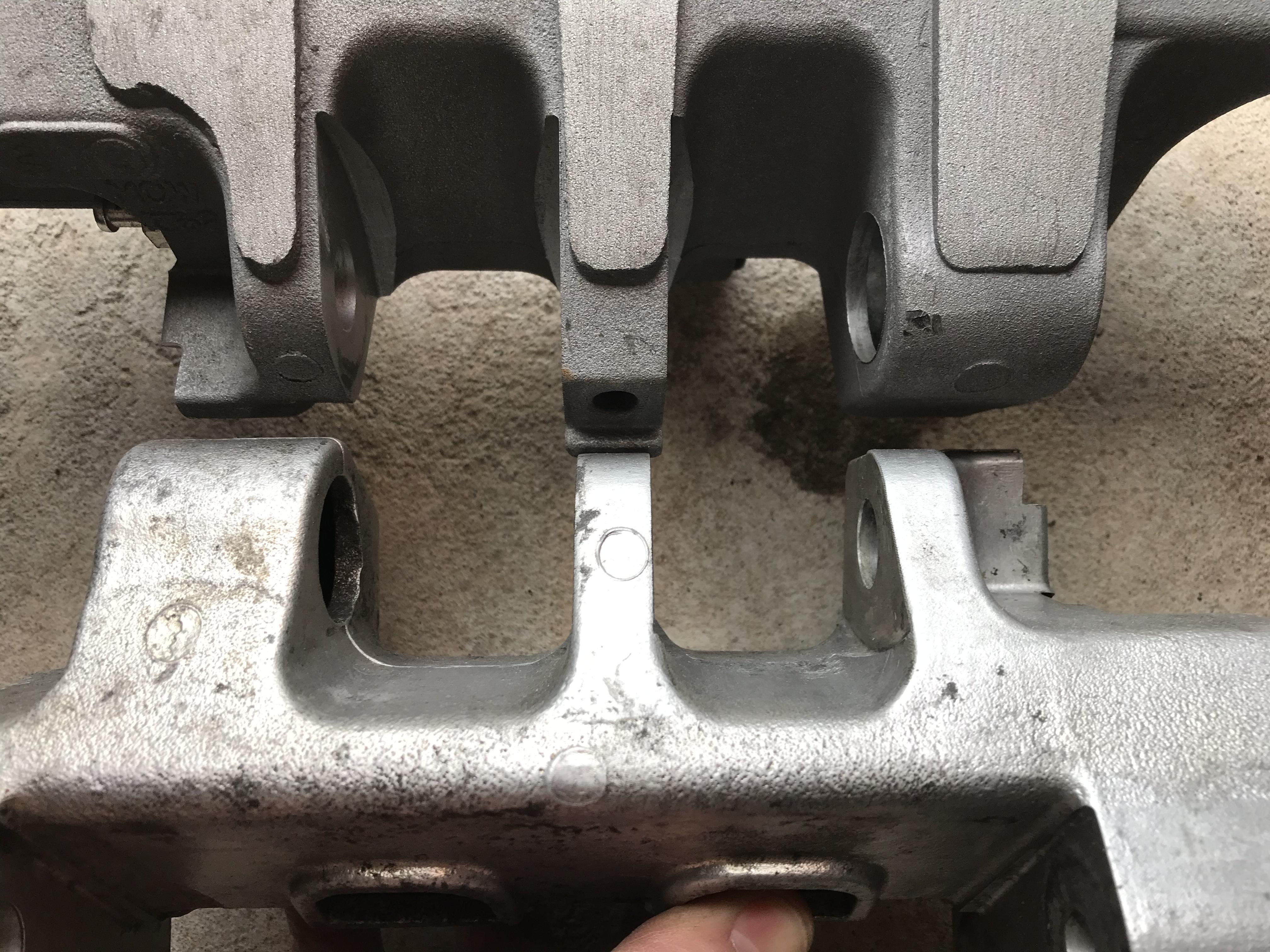
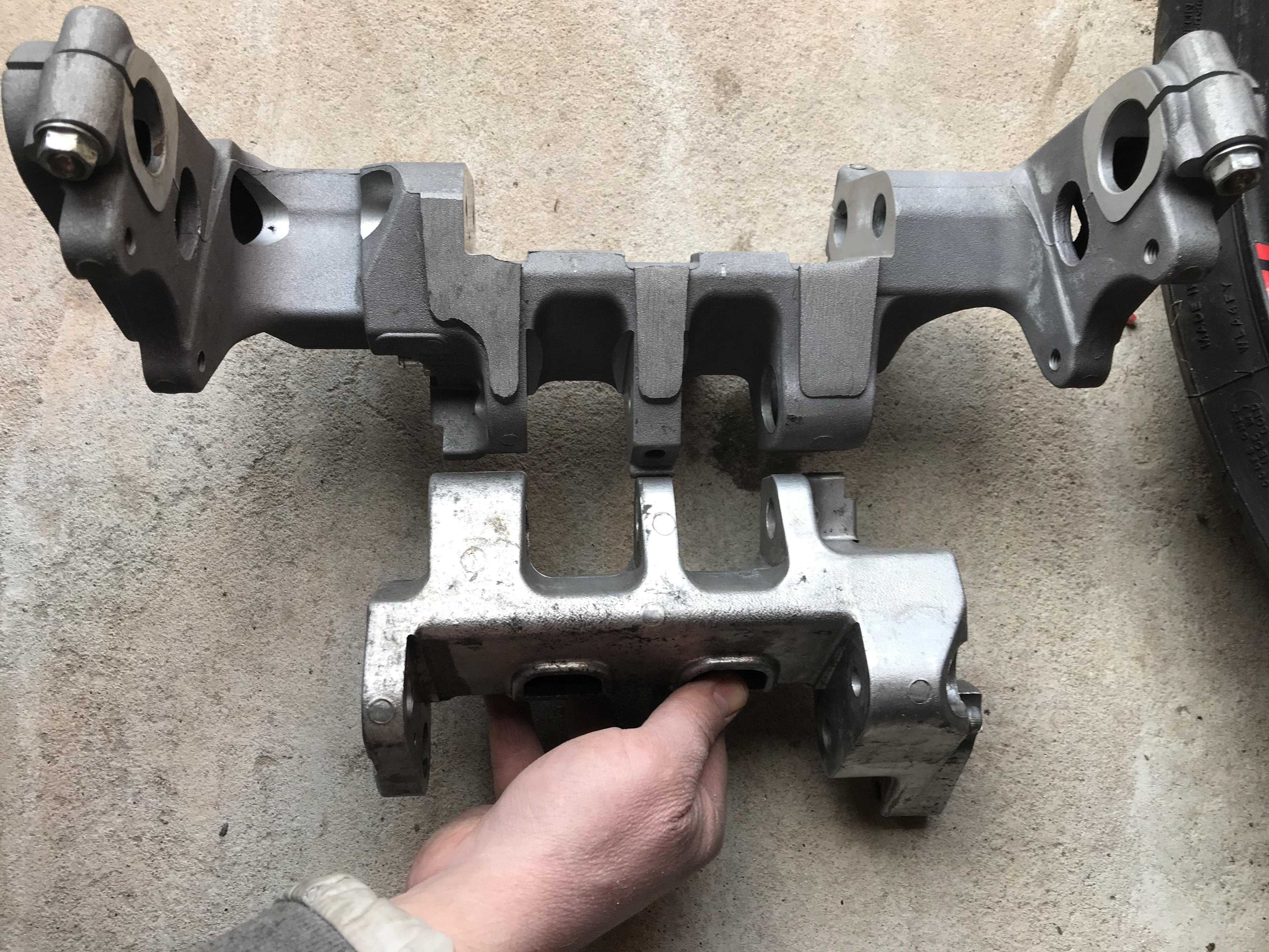
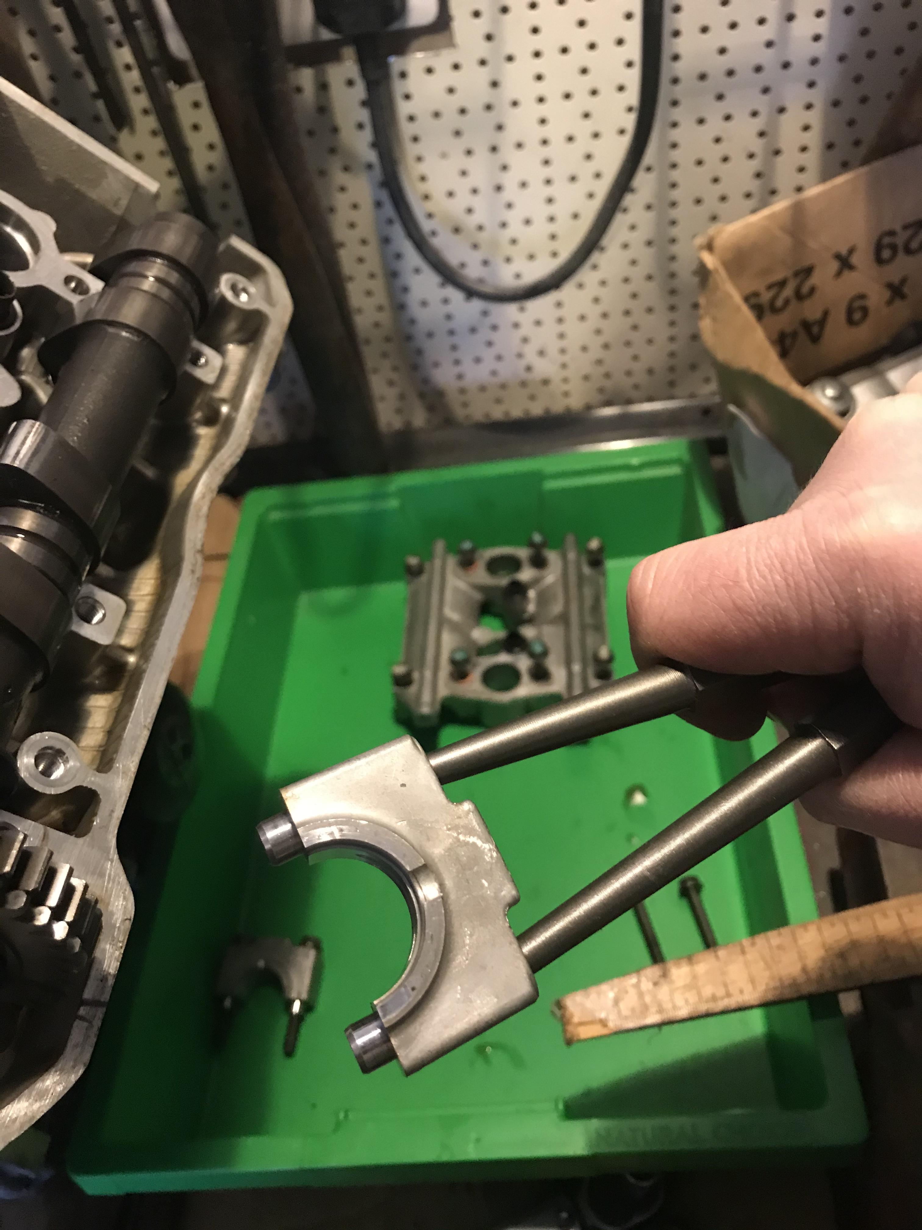
Hello All, Been toying with the idea of using an 8th gen cushion to mount different rearsets and possibly a slightly longer swingarm on my 5th gen (6th/8th gen swingers are slightly longer than 5th gen). For those of you wanting to swap cushions across the 5th, 6th and 8th gen bikes, here are some comparison pics. First off, they’re not a straight swap and they’re quite different in size! In this pic the 8th gen cushion is on the left and 5th gen is on the right. Note how the 5th gen item is narrower overall as the rearsets on that model make up the difference. 5th gen engine mounting gap, however, is much wider than the 8th gen. Here you can see the swingarm mounting points aren’t the same on both cushions. Note the centre lug is thicker in the 8th gen. I “believe” 6th gen cushions have the same spacing as 8th but please correct me if wrong. The above pic shows how much more substantial the 8th gen item is. 5th gen cushion is 1.264kg. 8th gen is a whopping 2.161kg - nearly double!!! Edit: the 8thbgen item has a little extra weight from the broken centre stand bolt stud stuck in its lug. Few grams maybe? I’ve decided to remain stock and keep weight down. Not sure how much more the 5th gen setup weighs with its rearsets (these form part of the cushion) but can’t imagine it adds up to the same as an 8th gen. Also curious how Seb’s rearset adaptors compare for weight. Can’t be very much (and they look sooooo cool!). Also not sure how the 6th gen cushion compares. I believe the mounting spaces are same as 8th gen but shape for rearsets is different. Just some info for anyone wanting to do these mods. Best, Stray
-
Those Gileras look wonderful!
-
Any advice on where to pour a bit of engine oil to aid first startup? Do I drop some down the spark plug hole? Drizzle a bit over the open area under the camshafts?
-
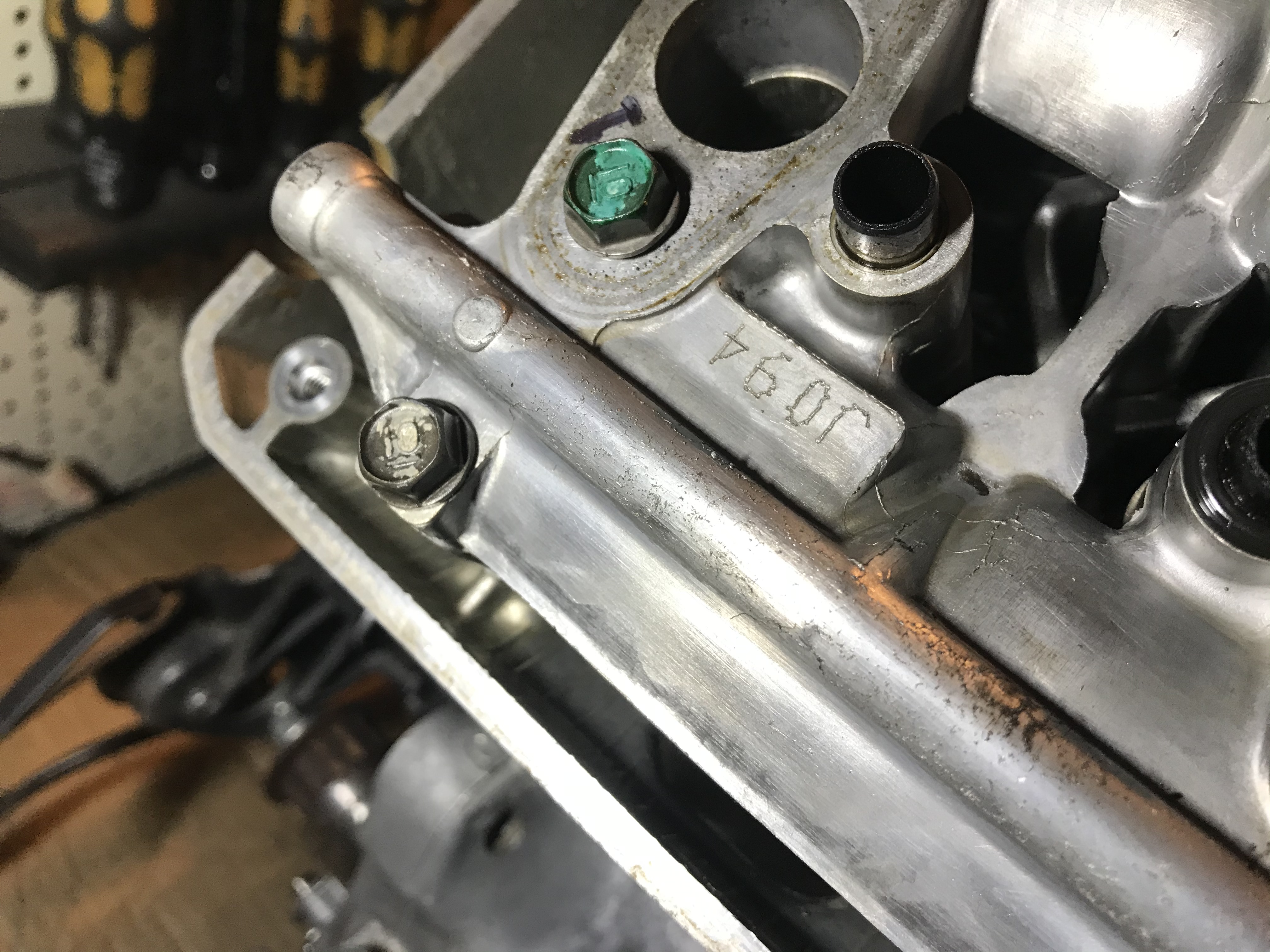
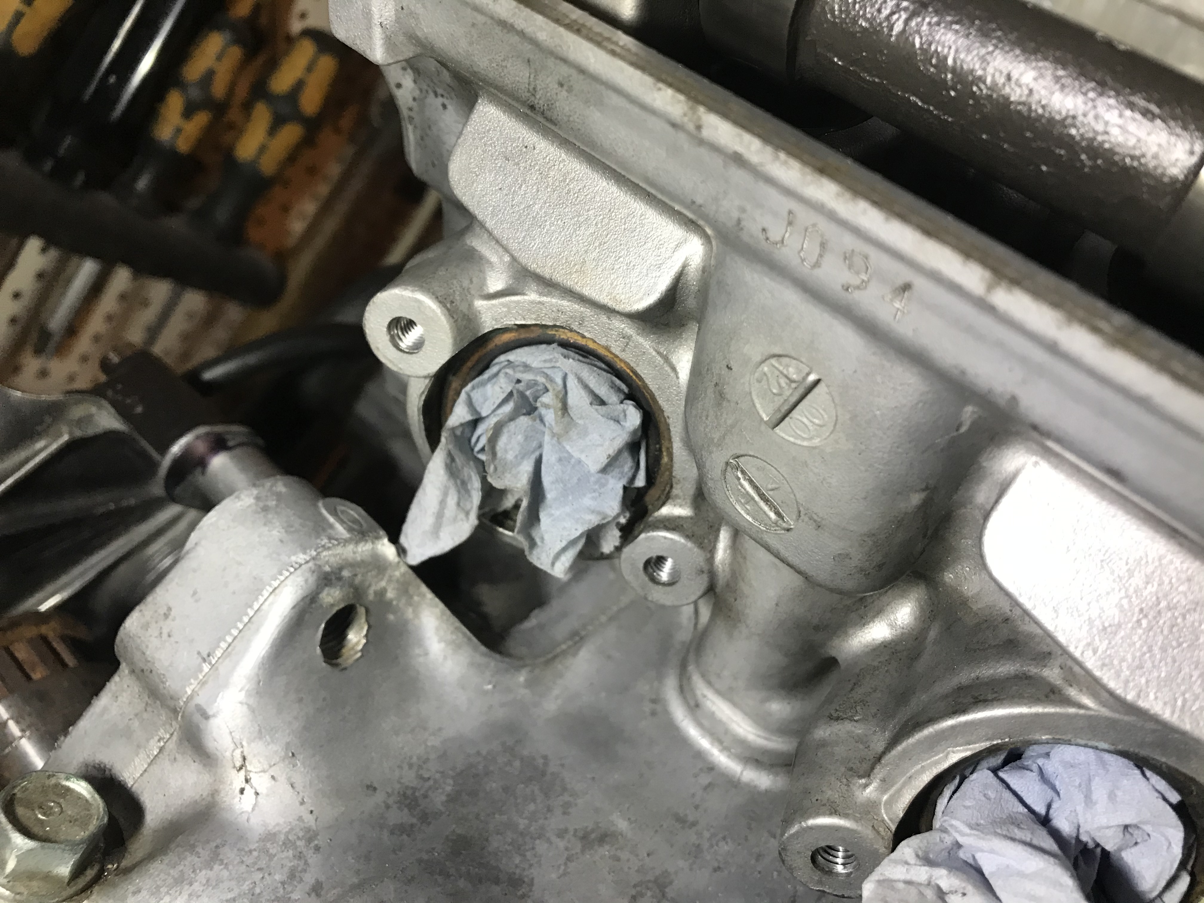
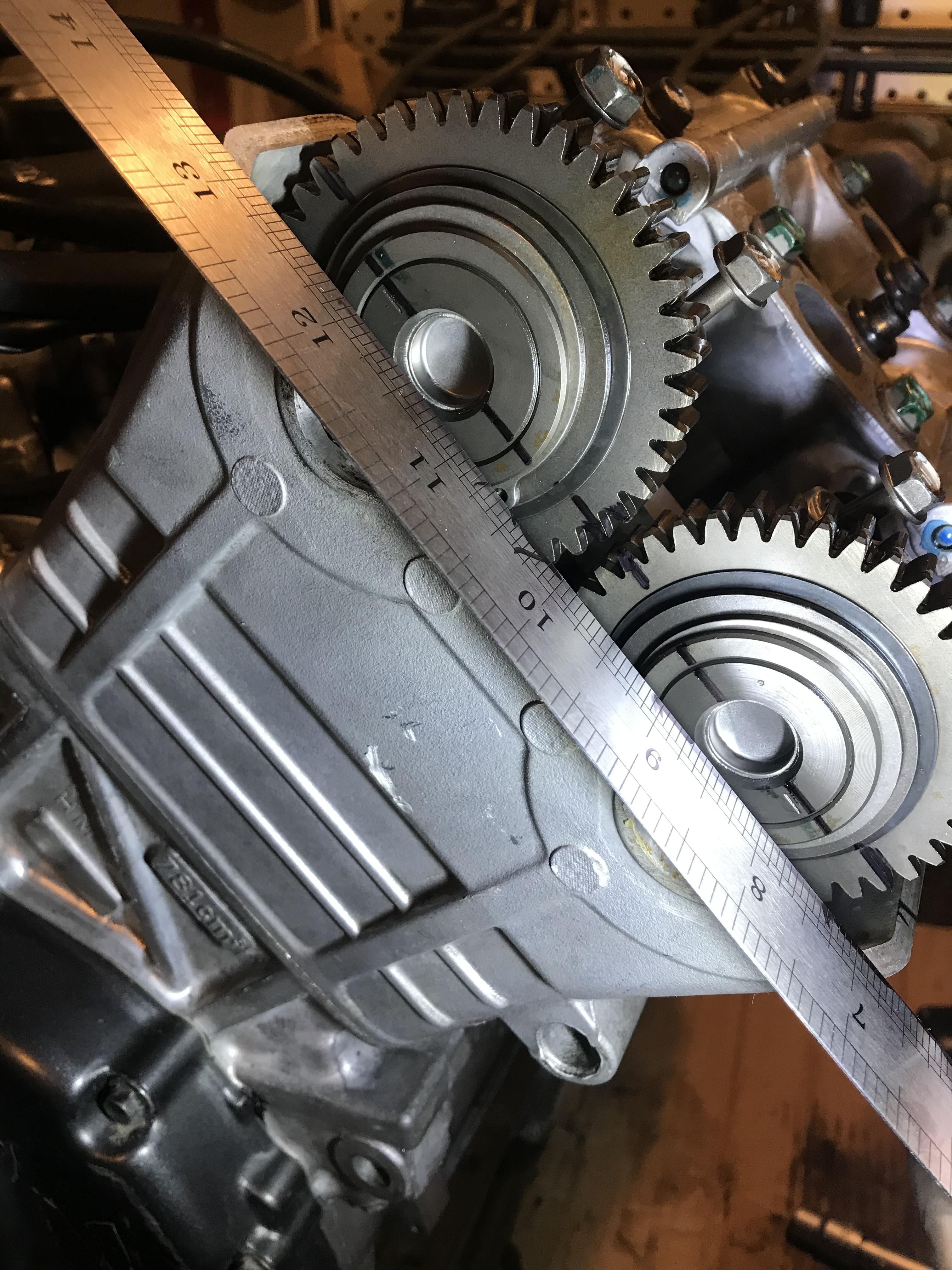
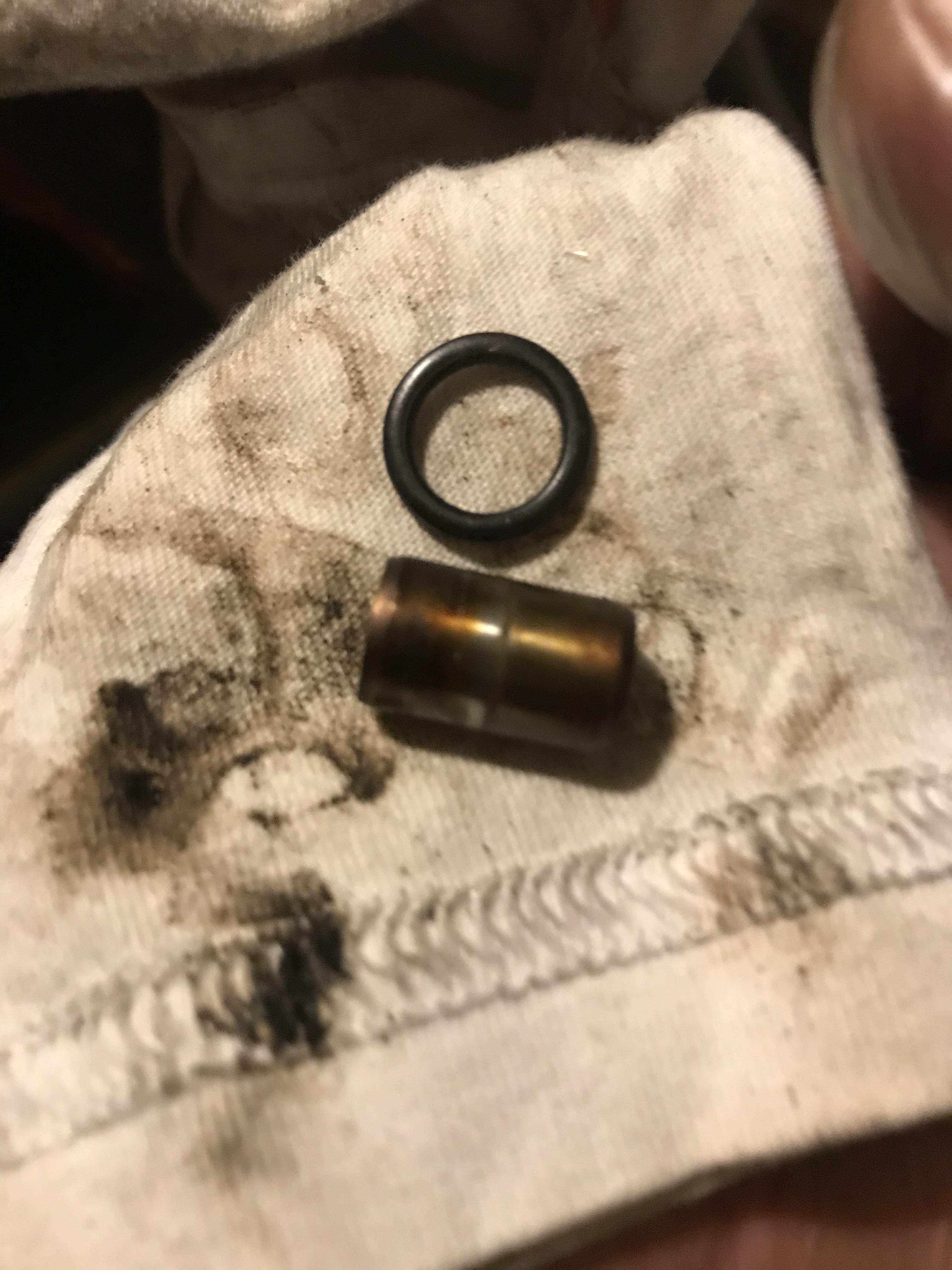
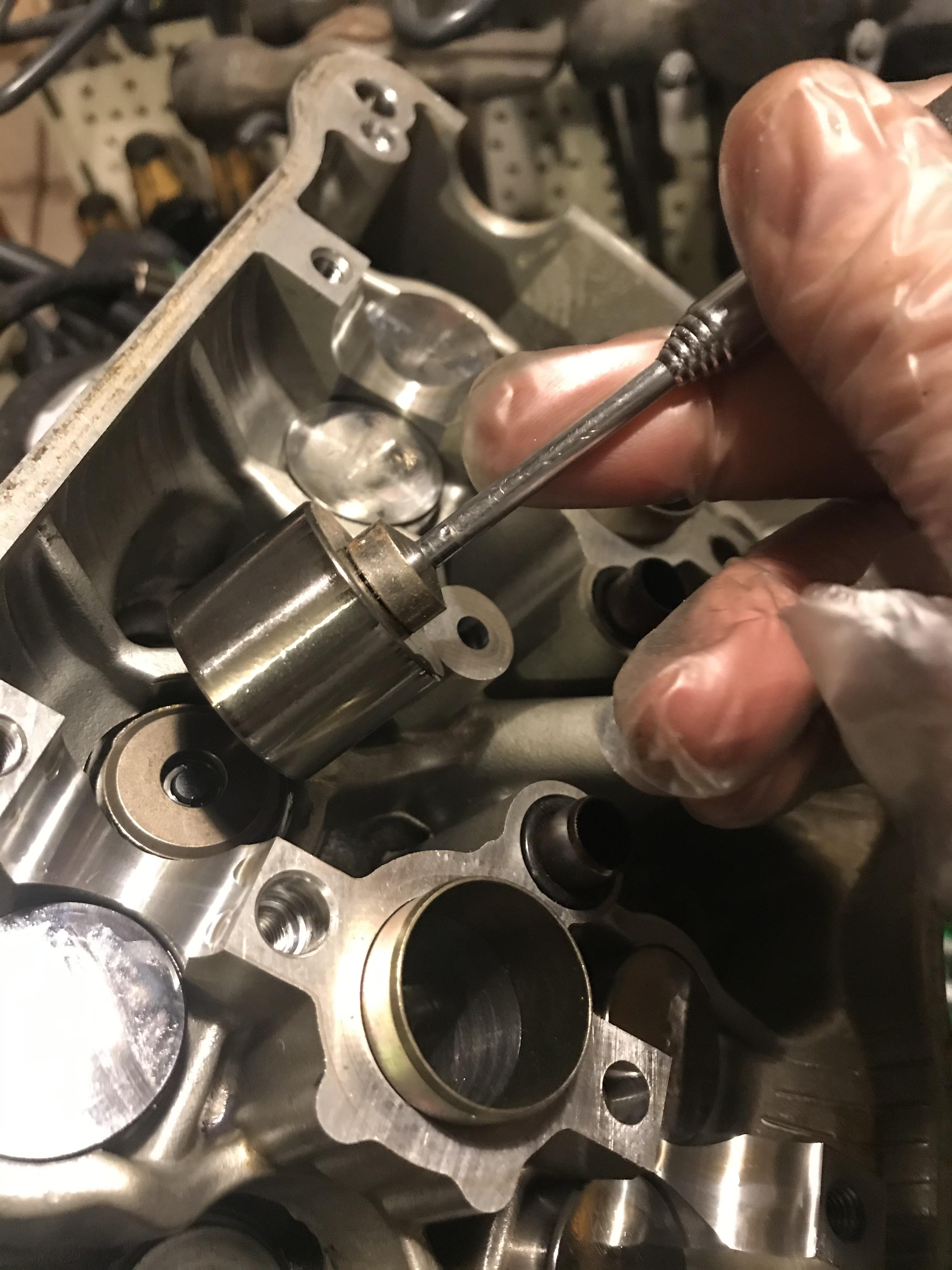
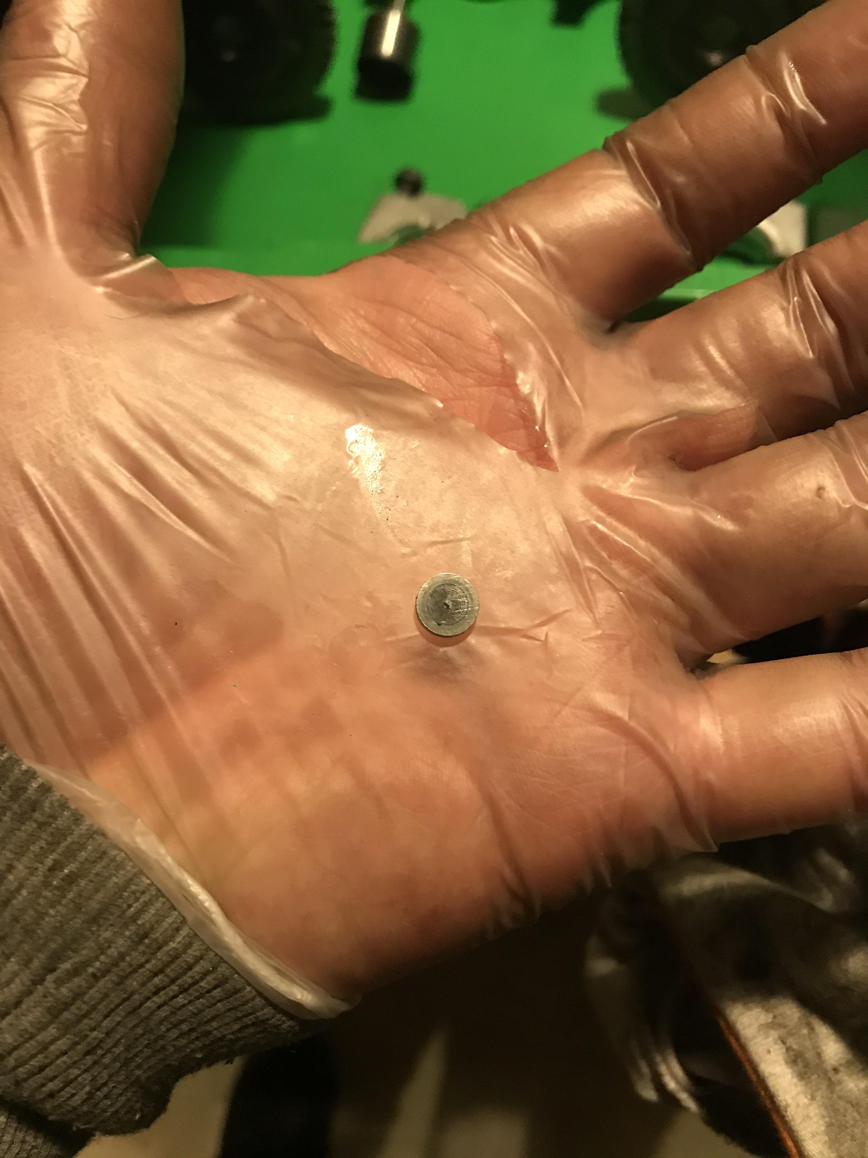
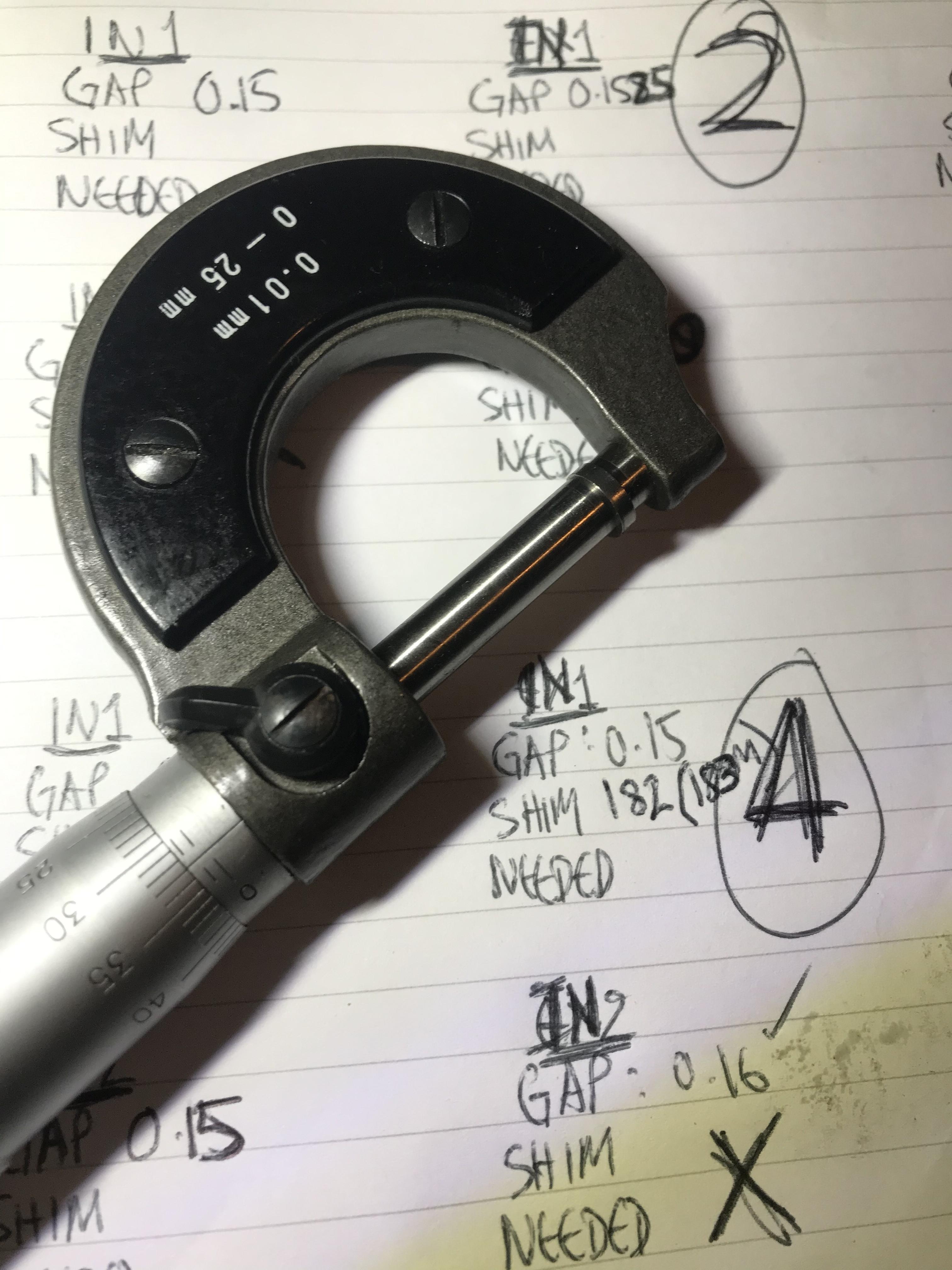
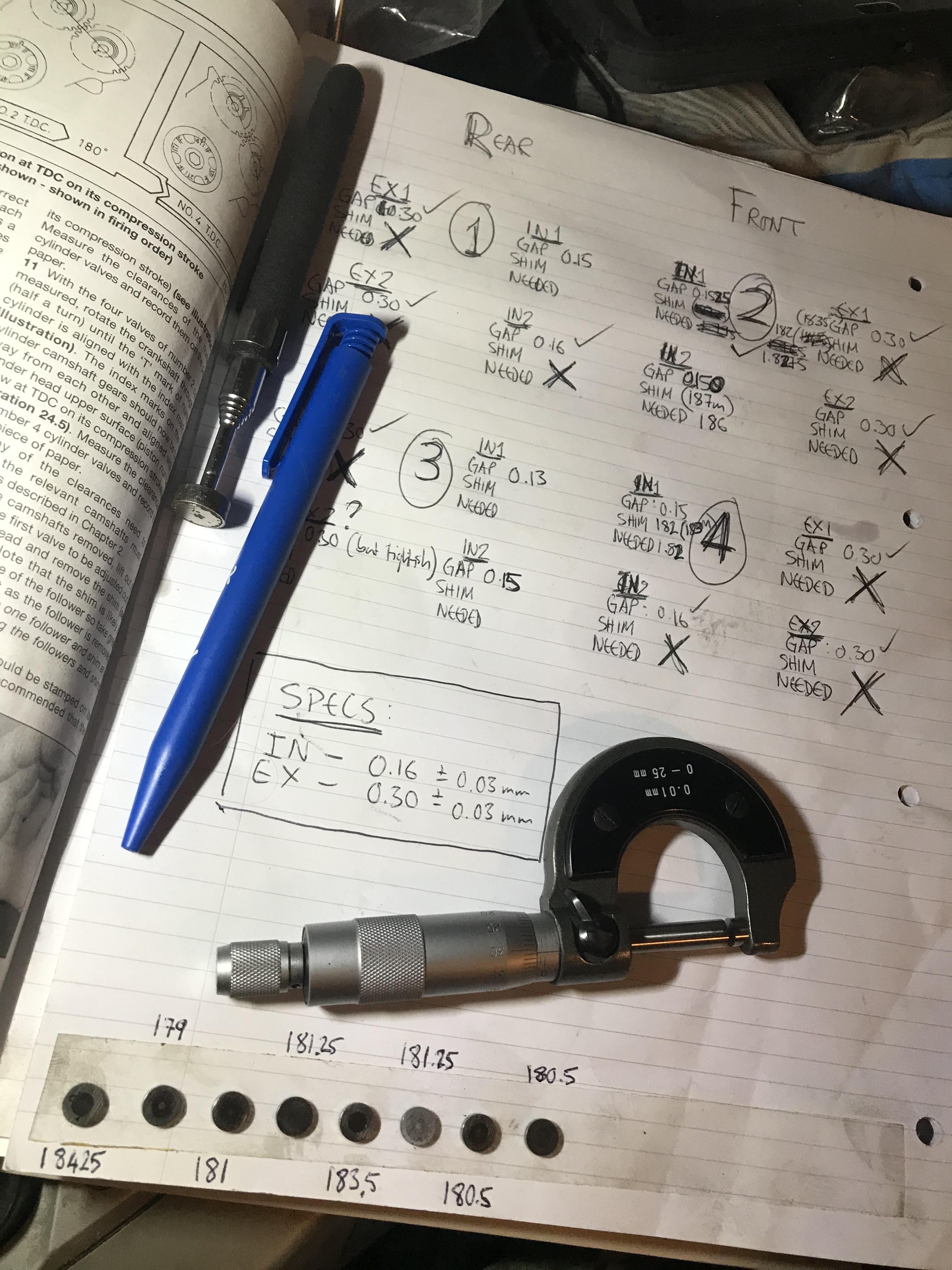
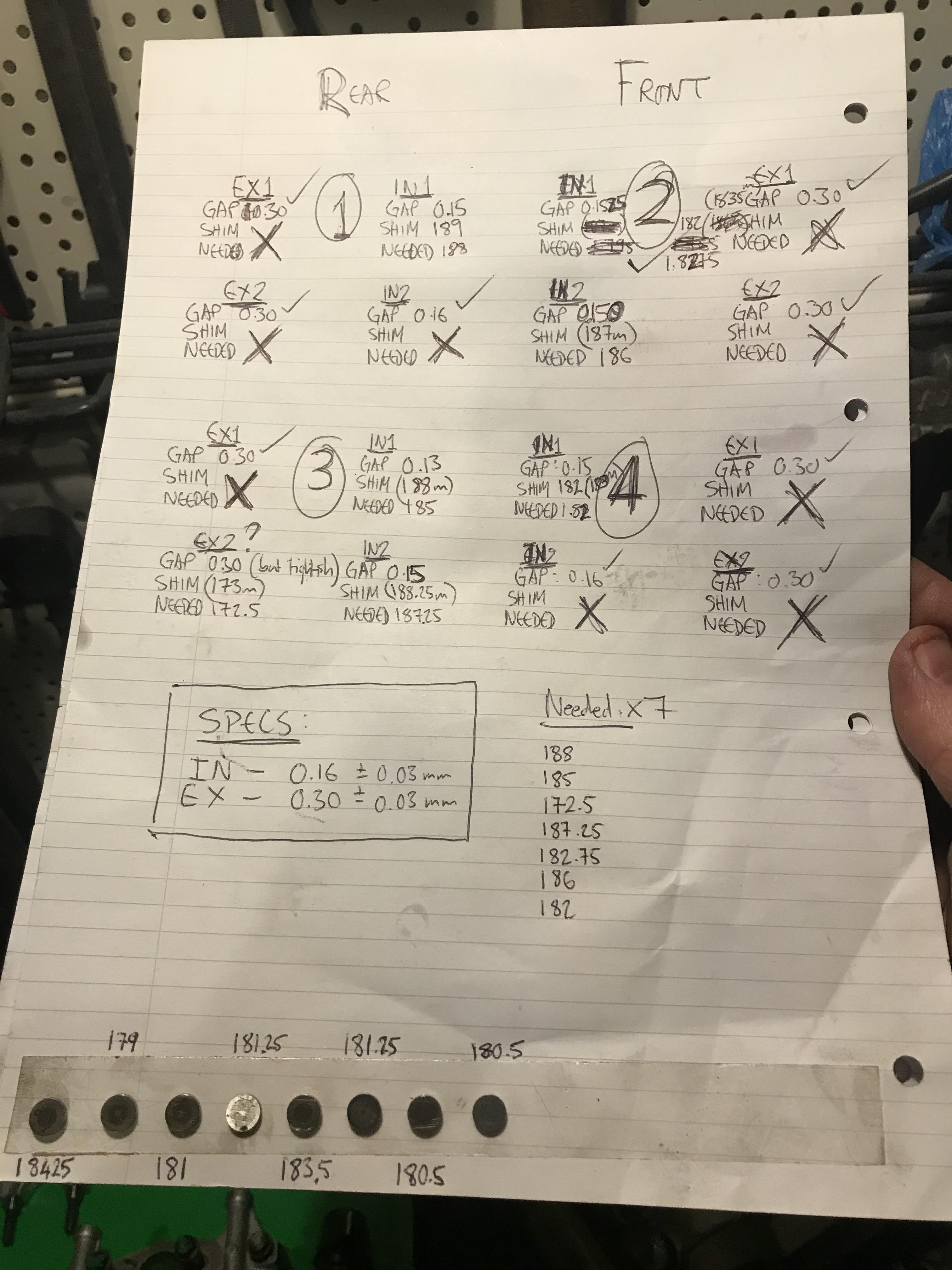
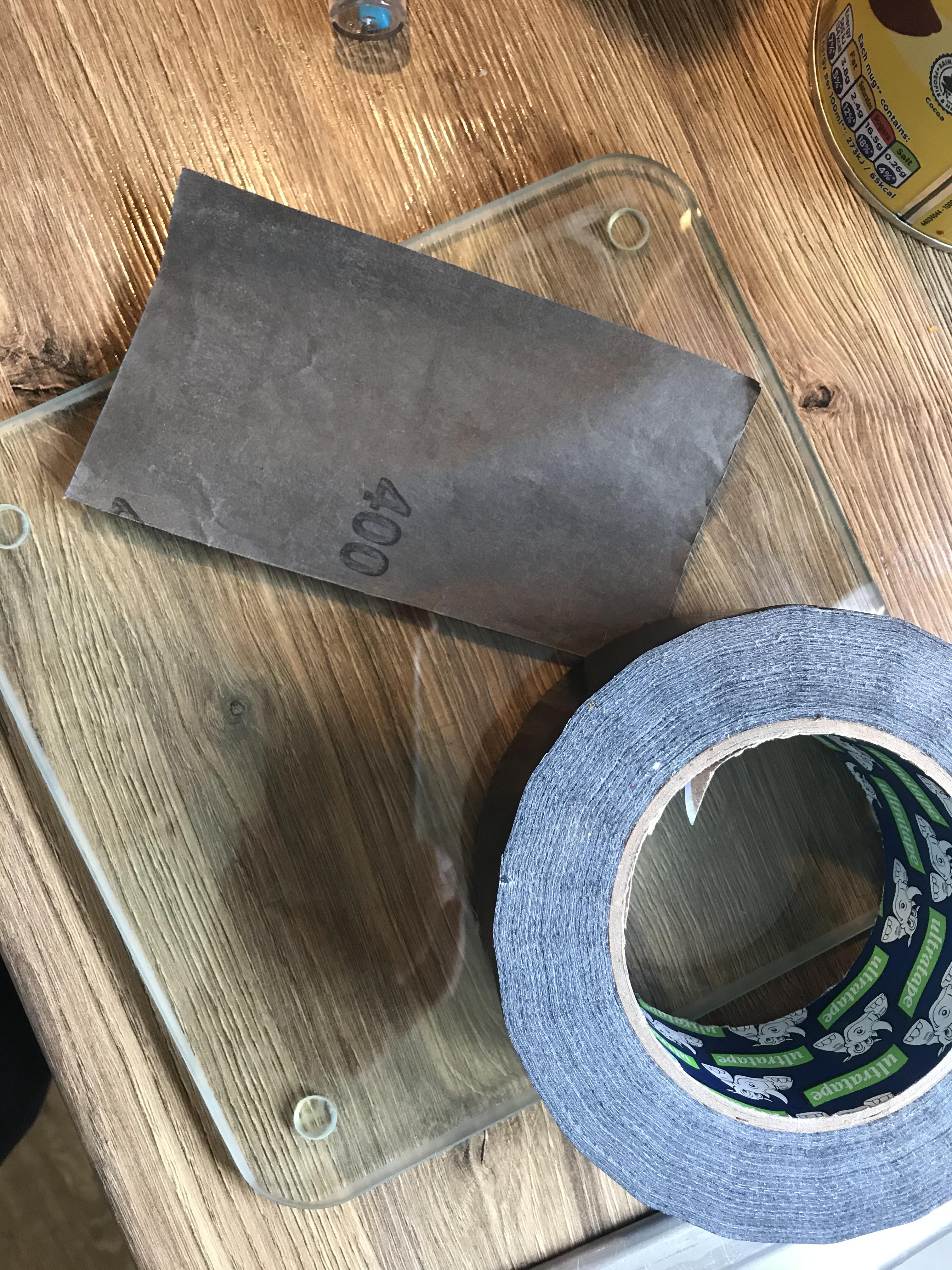
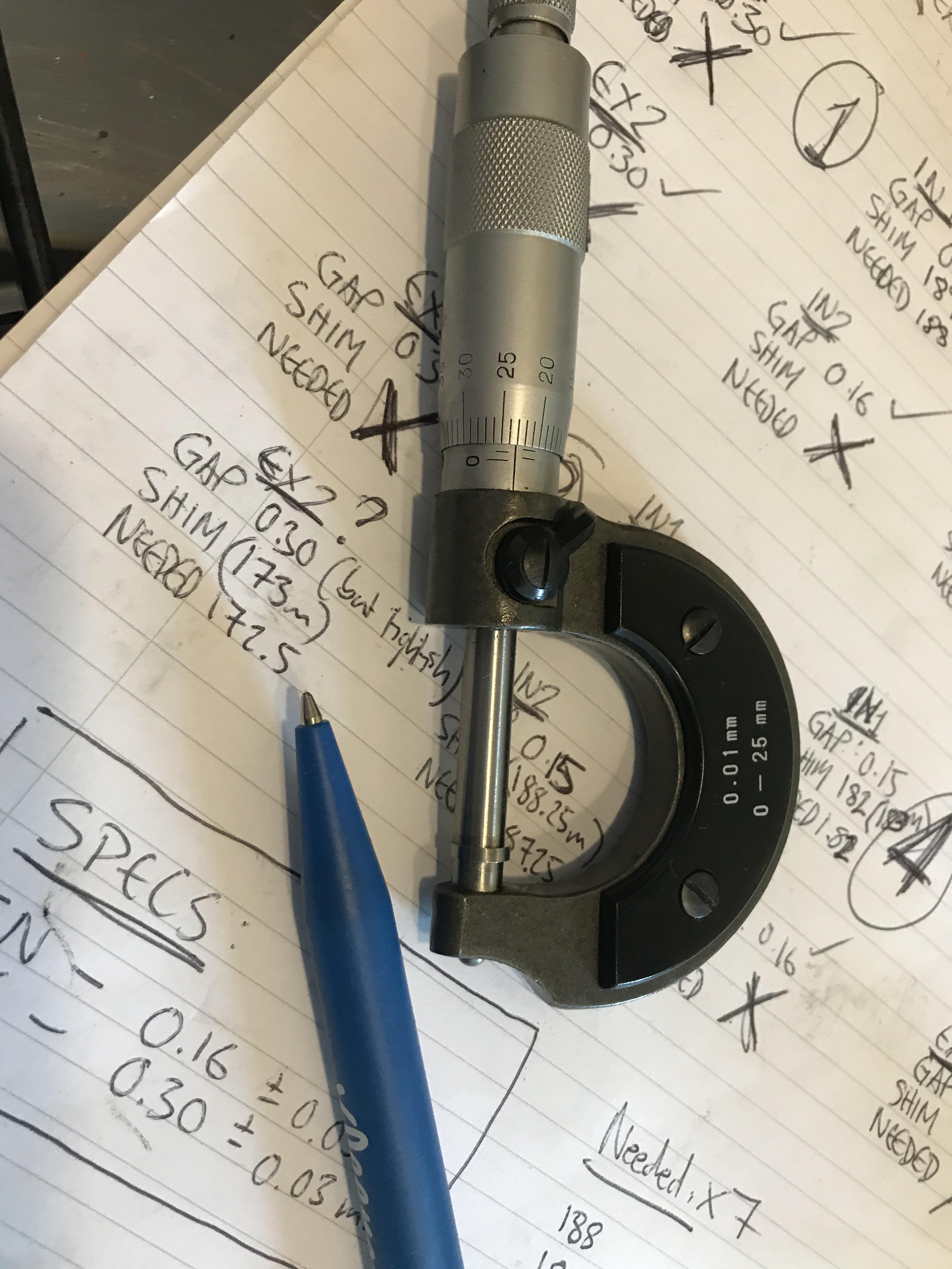
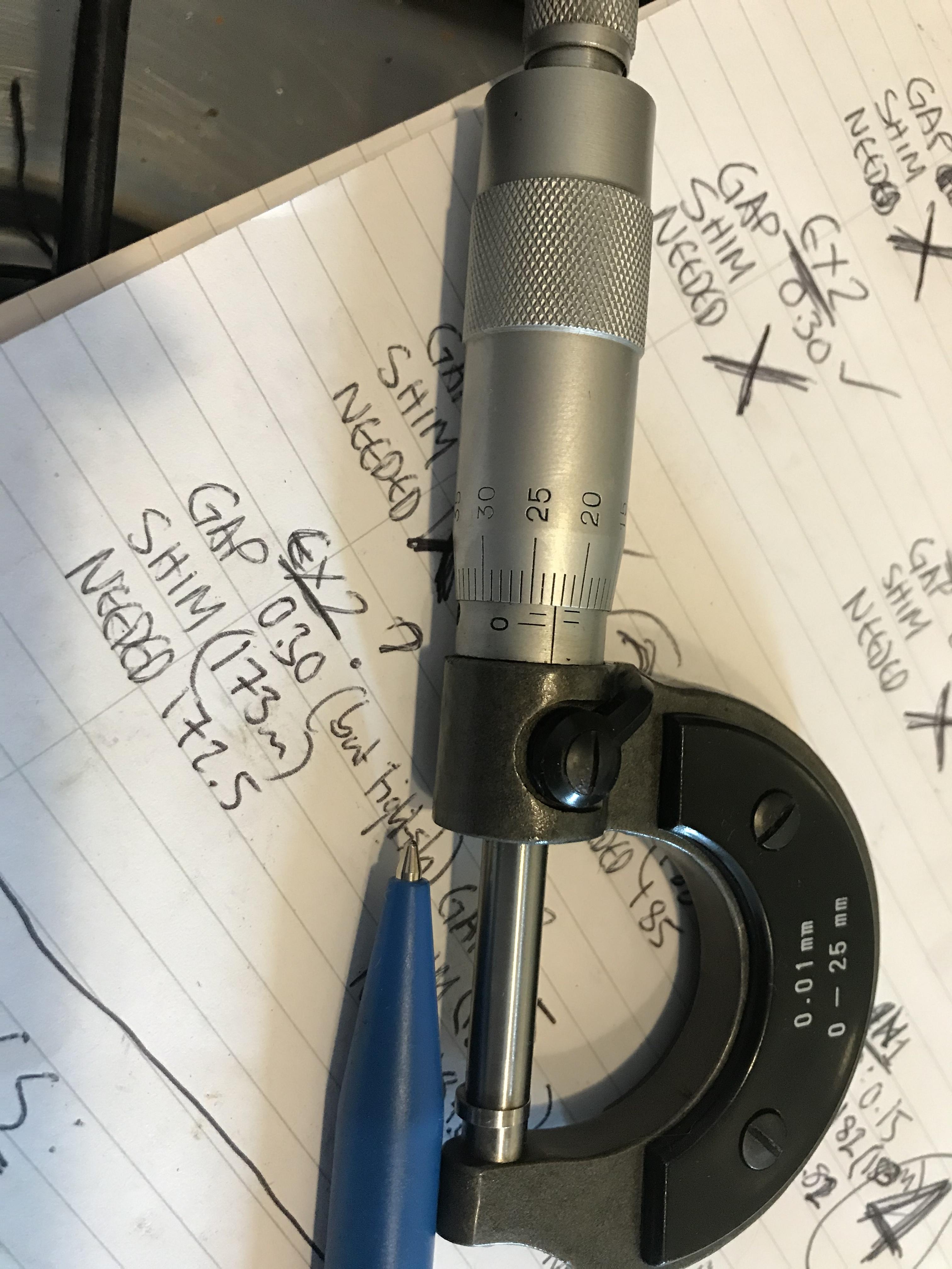
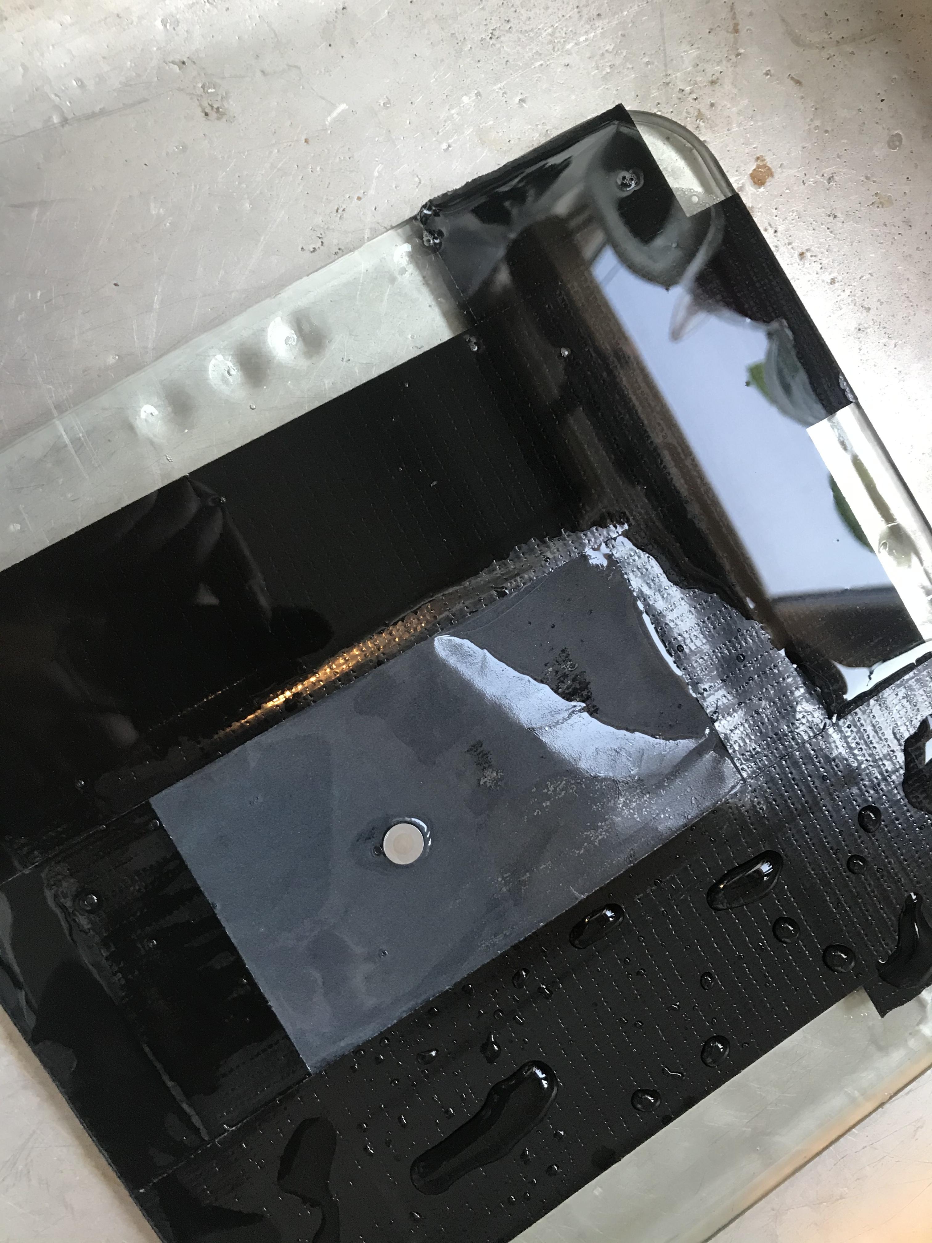
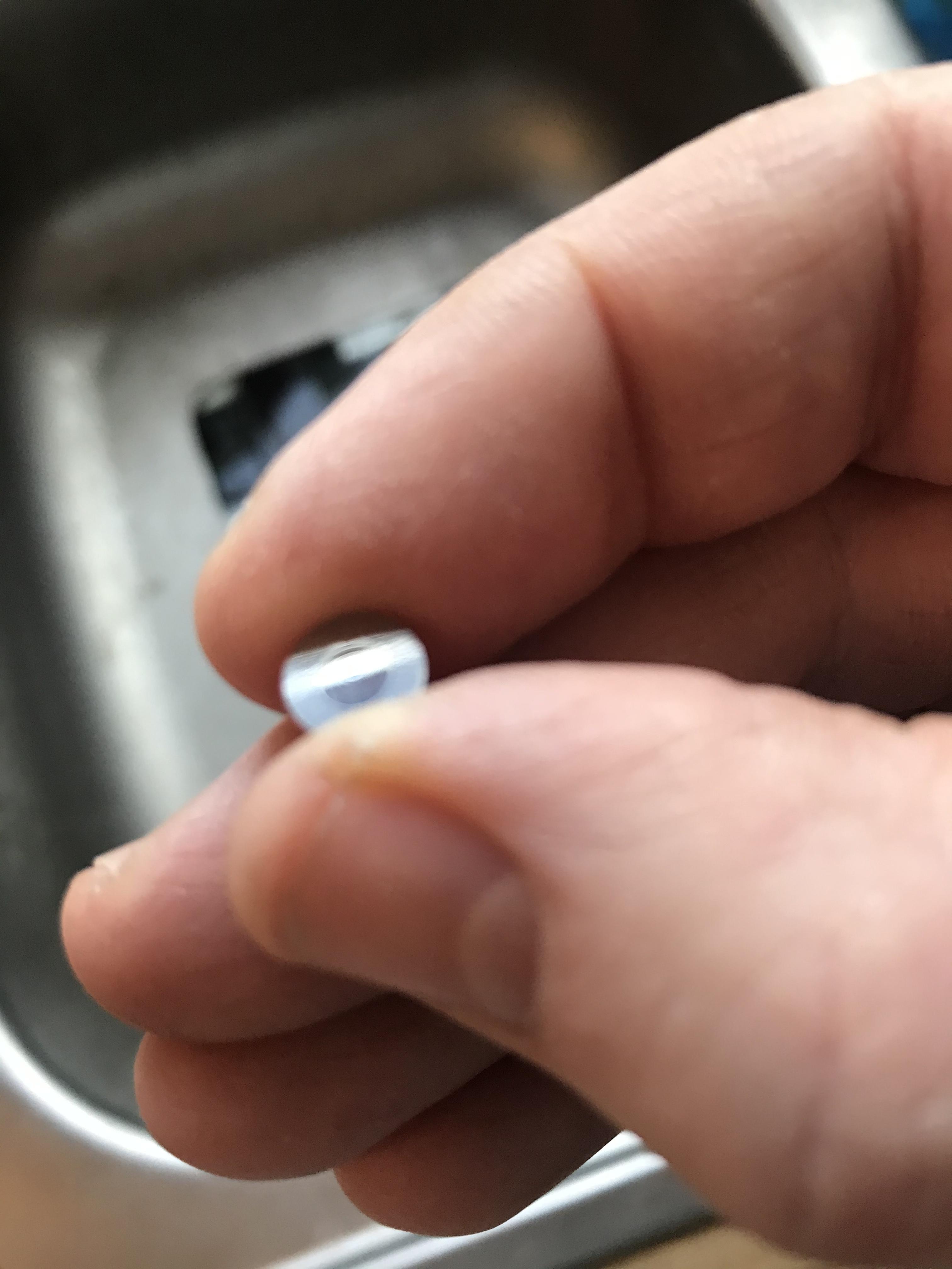
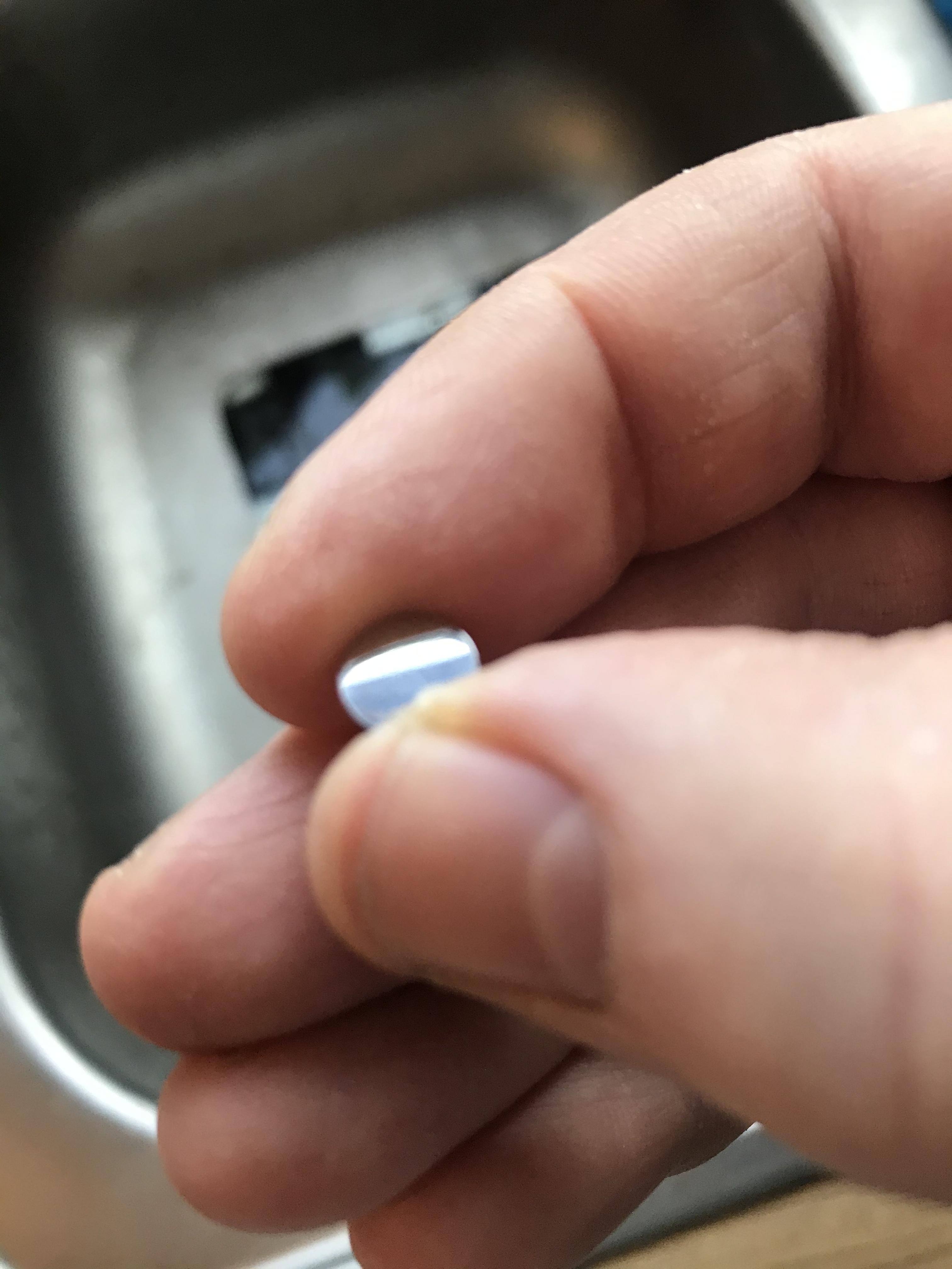
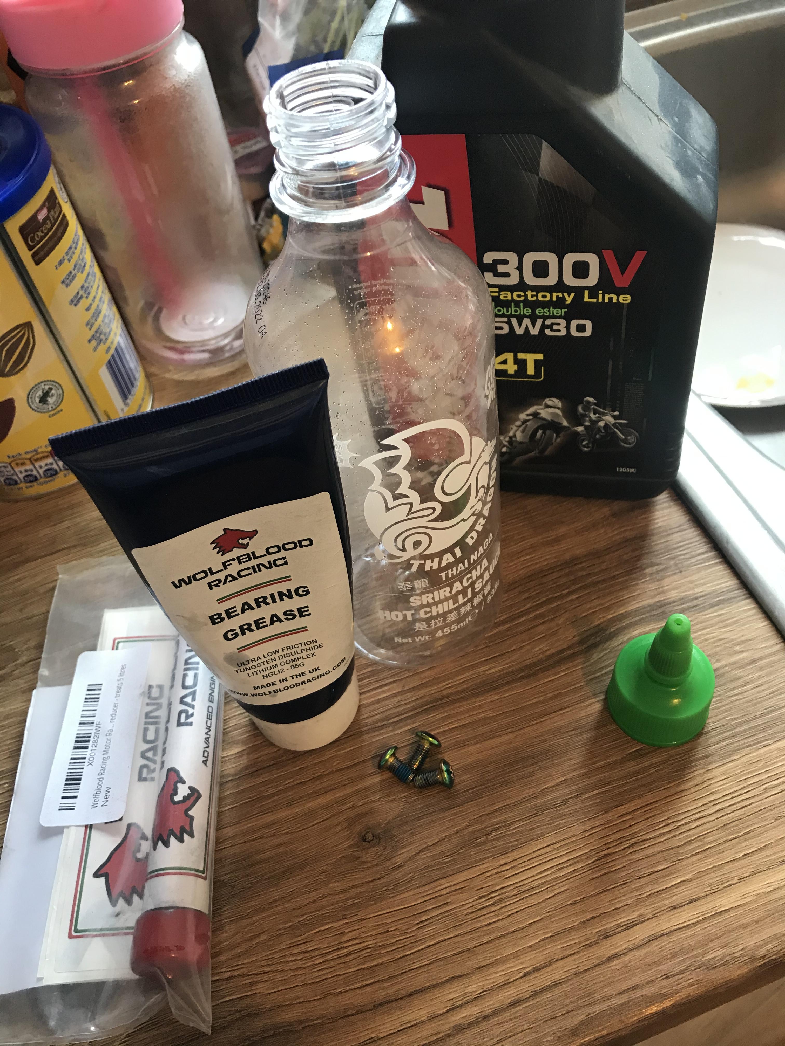
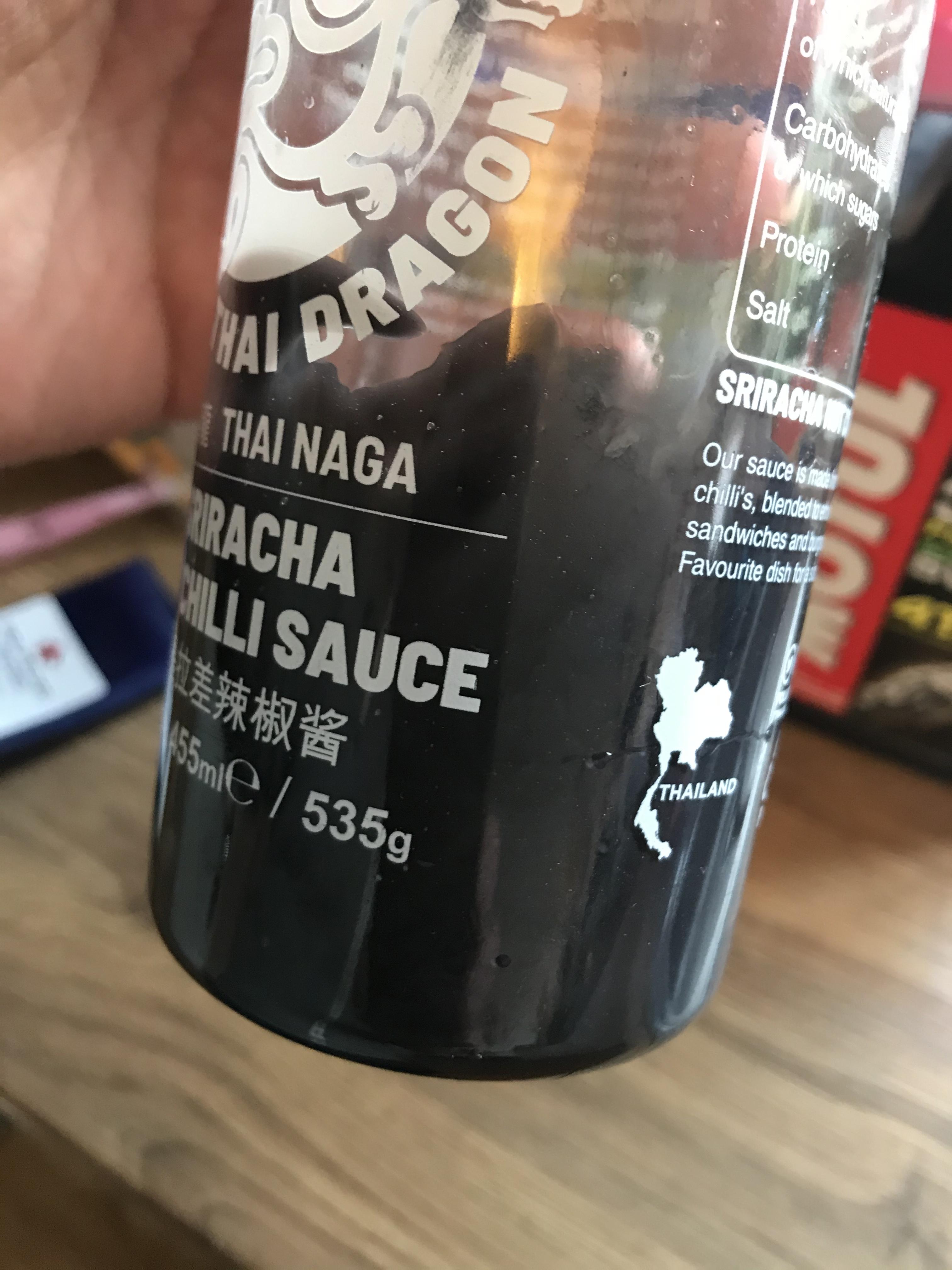
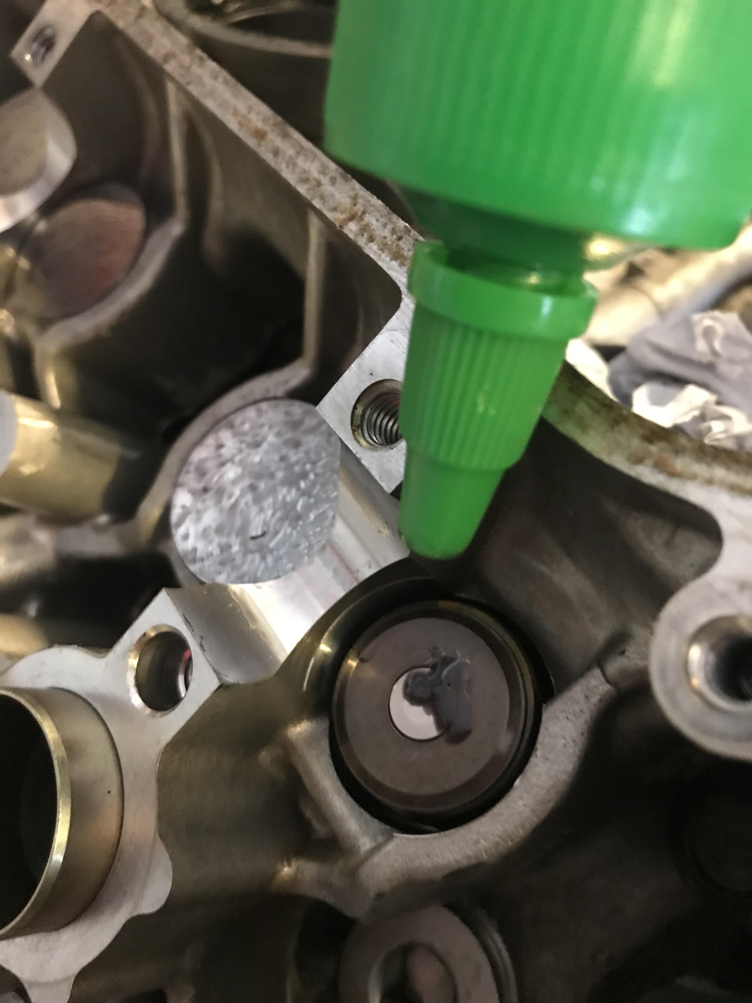
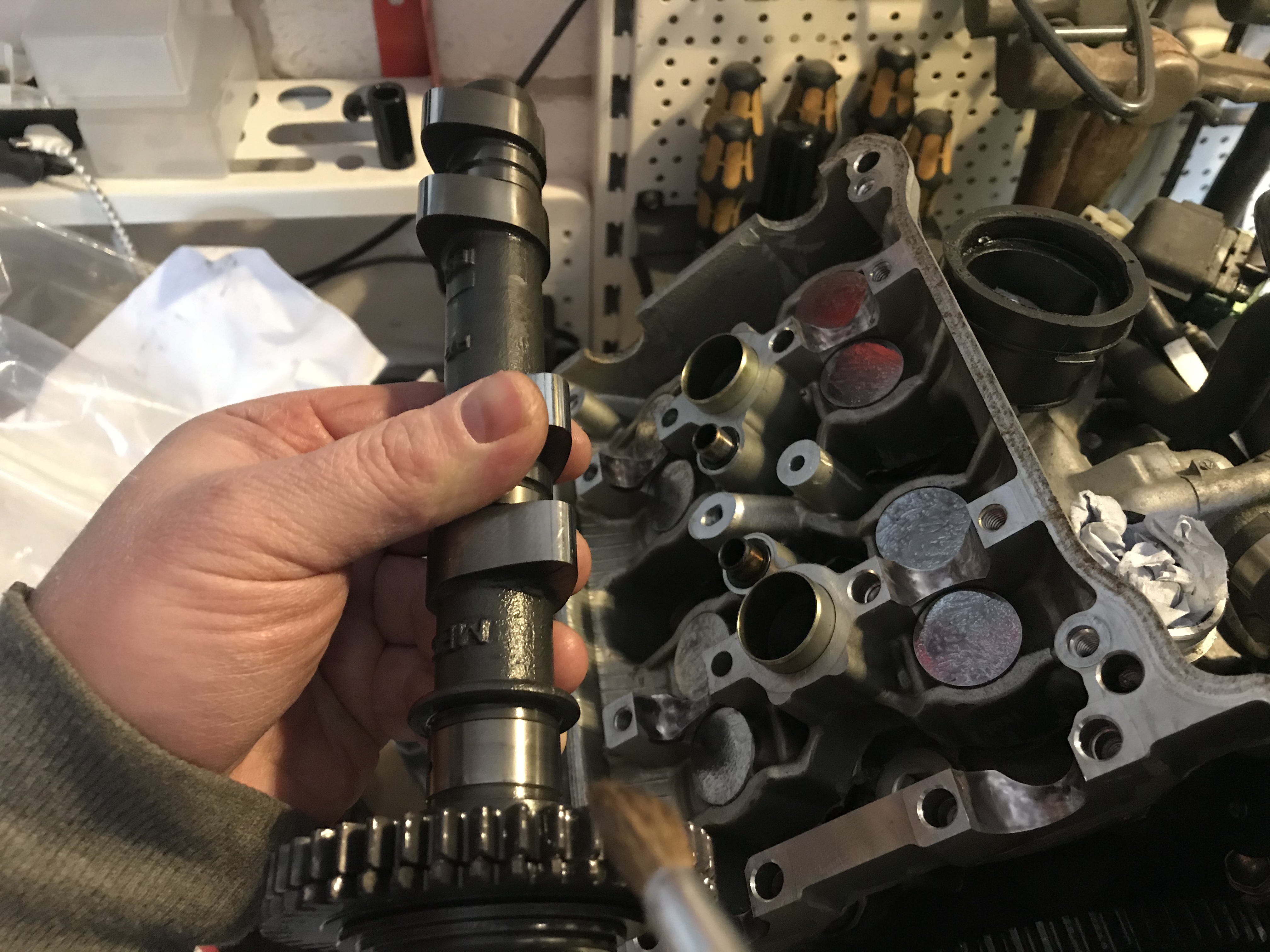
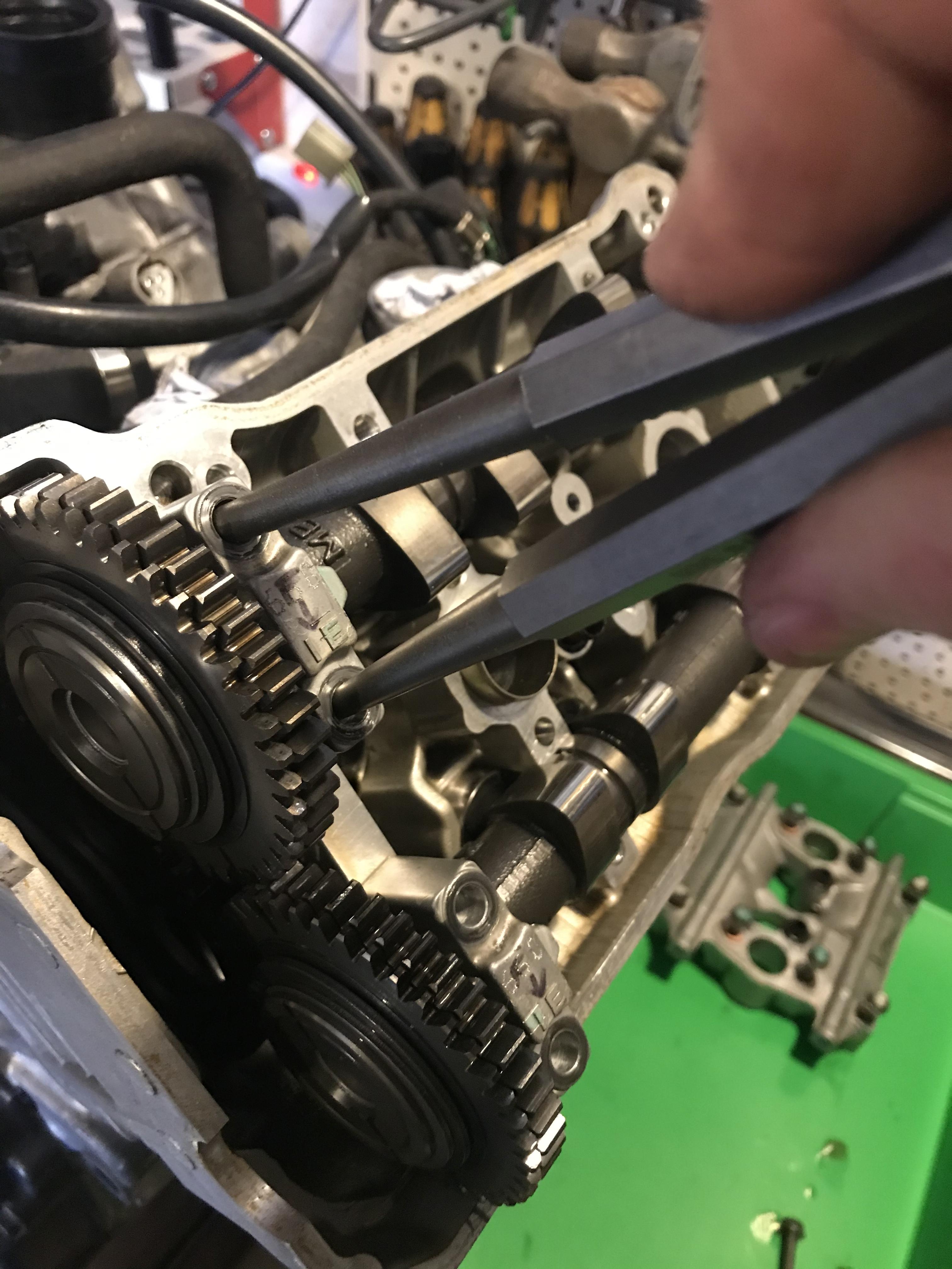
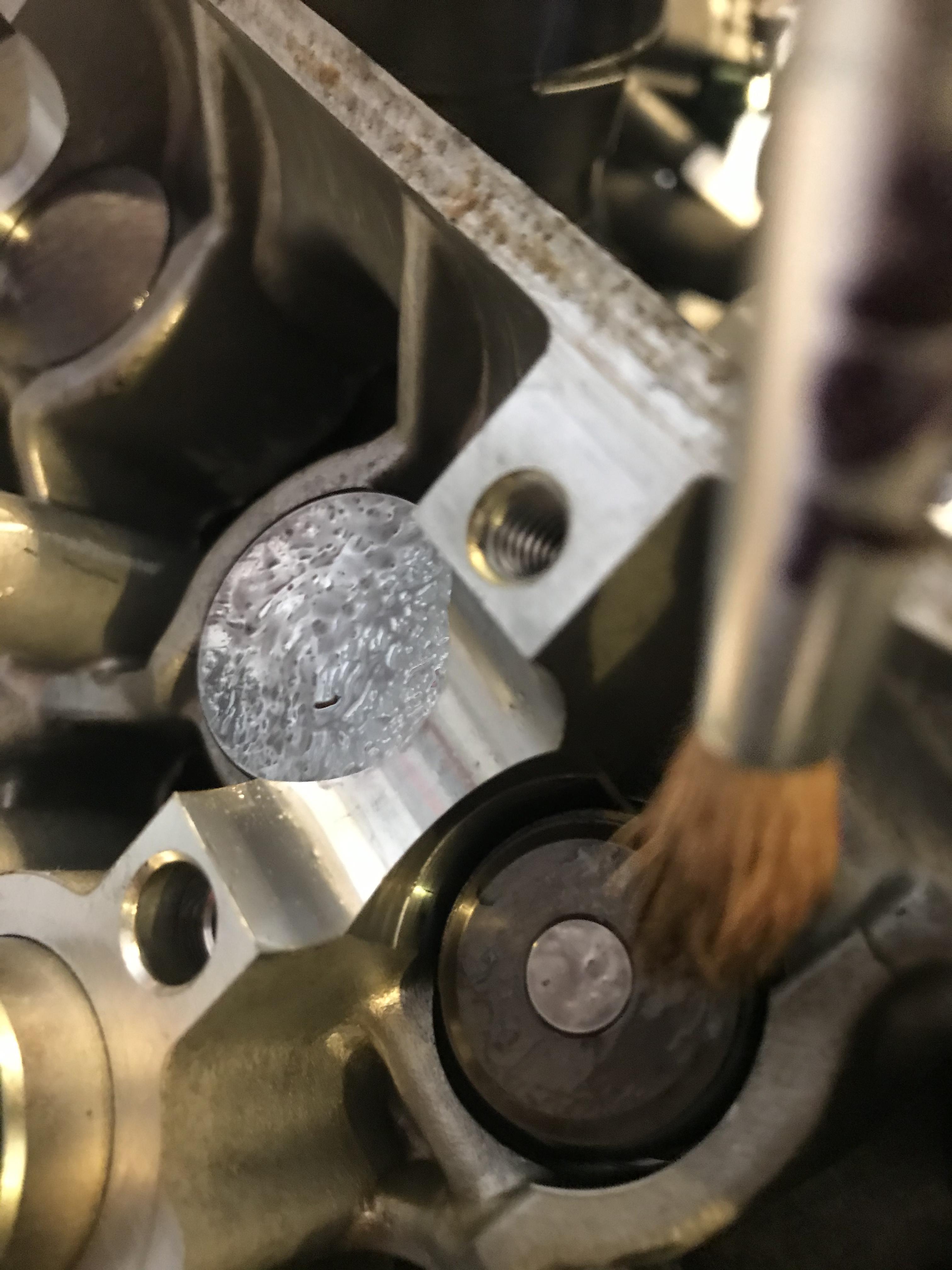
Hello Folks, Got a bit more done today - valve shims adjusted and buttoned up. More on that below. First, an update on some of the engine case markings. The ones that look like they were made by machine match the camshaft clamp numbers inside. Funny how I’ve never noticed before (although my engine has never been clean enough to make them out before!). Markings on outside of cylinder head (facing throttle bodies)... ...matching camshaft clamp. Different code in front and rear cylinders and they both match their respective clamps. Must be paired up at the factory. Also, that “stress cracking” described earlier is all over these engines. Inside and out. Even the cam clamp has some. I opened up one of my scrap engines to harvest the shims and that one had crazing all over too. Must be a casting flaw as Dangeruss says. Anyway, on to the valve adjustment. First thing is to spin the engine with a 14mm socket on the crank until cylinder 1 T mark lines up with the cutout on the clutch cover (no photos of this - sorry!). The gear markings must be facing away from each other and parallel to the cylinder head. If they don’t, spin another 360* until they do. You’ll have to spin the engine separately to measure each cylinder as per the manual. It’s simpler if you go 1, 3, 2 then 4. This helps keep the lobes properly aligned and you can separate the front and rear cylinder heads. Fit the feeler gauges between the cam lobe and shin bucket to measure clearances. Intake is 0.16mm and Exhaust is 0.30mm with a tolerance of 0.03 on both. Any shims out of spec must be removed, measured and replaced with an appropriate size to bring the gap back into spec. With only 10k miles I didn’t expect much to be wrong but there were some that required attention. One of the intake valves in cylinder 3 was on the very edge of spec at 0.13. Here are my notes: Had a few old shims from another engine so I stuck them on a strip of double-sided tape along with micrometer measurement in case they could be reused. Initially, I planned on getting everything exactly in the centre of spec but even with playing “shim shimmy” that was impossible. I’d have to settle for good enough. Once measured the head would need taking apart so the shins can be accessed and swapped. Before undoing any bolts I like to mark the cams with sharpie and a ruler so they can go back in exactly the same way. Also I colour in the teeth where cam gears meet for extra precision. Undo cam holder bolts in a crisis-cross pattern about 1/2 a turn at a time until loose. This helps the clamp rise true and not warp. If the cam clamp binds on one side it can start rising skew - just tickle it with a rubber mallet to keep it flat. If you’re struggling to remove cam gear clamps try sticking some close-fitting tools in the hole so you can wiggle them free. I used some chisels but screwdrivers will do. Just avoid going deep enough to damage the bolt threads. Wiggling and judicious application of a rubber mallet will have it all apart briskly! I like to keep bolts in the same holes just in case there are any minor variations. Best not to mix up your hardware. Good chance to give the PAIR and spark plug dowels a good clean. My o-rings looked OK so they got reused. Now use a magnet to pull out the shim bucket so we can remove the shim under it. Careful: sometimes the shim comes out with the bucket and can roll free. I spent 15 minutes hunting one on the floor and another 15 minutes fishing one out of the engine with the magnet... Here’s the little shim: 7.48mm diameter. Tiny little things! They don’t seem to have a way up as they’re factory fitted with their size markings facing both up and down. I noticed where they meet the valve they develop a small circular wear mark. The side meeting the bucket has a bigger circular wear mark. This, along with minor swirls on the buckets suggests these spin as the camshaft lobes hammer them. Interesting design... Another observation: virtually none of the size markings are exactly right. The micrometer found most markings were wrong - only two on the whole engine were bang on! Here’s an example: shim is marked 182 but micrometer says it’s 183. All measurements finally finished. I was planning to get everything to exact spec (0.16 intake and 0.30 exhaust) but shins are only available in 0.05 increments (or 0.025 from dealer at eye watering prices, so I couldn’t get it bang on no matter what I did. Then I read the KevCarver has had success with sanding his shims to the exact size he needs, so I thought let’s give it a go! Got a piece of flat glass, some worn 400grit wet-and-dry paper, duct take and a drop of dish soap. Experimented on the slightly tight exhaust valve that only needed 5 hundredths of a mm (mm, not inch!) removed. Took measurements before sanding. Was 173... ...and after sanding (now 1725). Sanding is done in a figure 8, measuring every few strokes and turning the admin 90* every now and then to keep the cutting even. Within about 5 mins I’d rubbed off the 5 hundredths and the rubber side was smooooth! But upon inspection of the shim it seems the side I sanded now had chamfered edges and the face was ever so slightly domed where I probably rocked the shim with my finger whilst sanding. Compare the straight reflection on the original face... ...with the slightly domed reflection on the sanded face. See how it’s rounded on the edges? Probably from rocking when rubbed and possibly where water made the sandpaper warp. Very hard to hold these shims flat as they’re so small. Might work better with shims of a bigger diameter (like on my Yamaha) but these are just too small so I decided not to sand any more of the VFR ones. Time to swap the two shims I could service and button everything back up. For this I’d need my own home-made camshaft moonshine to keep things smooth on first startup when there’s no oil. For that we need equal measures of engine oil and WS2 grease, with a pinch of WS2 powder to taste. Similar sort of thing to molly EP grease only slightly more slippery (and a bit more expensive!). All thrown into a sriracha sauce bottle with 3 old bolts to help mix things up. Give the bottle a good shake and let the bolts mix everything together nicely. It’s a homemade engine assembly paste, I suppose. With a bit of luck the WS2 will burnish into the cam lobes and journals to help reduce wear. This special sauce is then dropped on the shims, buckets and most importantly on the cam bearing surfaces. A paintbrush helps achieve good coverage. Also brushed this sauce on the cam gears and cam journals to minimise damage on first startup. At last everything is back in position and properly greased up. With everything in place it pays to spin the motor a few times and recheck valve clearances. On the rear bank I found some of my clearances had shrunk by 0.005. Much swearing ensued!!! Upon inspection I realised my torque wrench was set to 13Nm instead of the specified 12Nm. So I loosened all the bolts and redid them at 12Nm, at which point my clearances were fine again. You MUST use a torque wrench for this procedure as just a bit too much could wear your camshaft bearing surfaces and mess up your valve timing! Hope this helps someone on the same journey. Stray
-
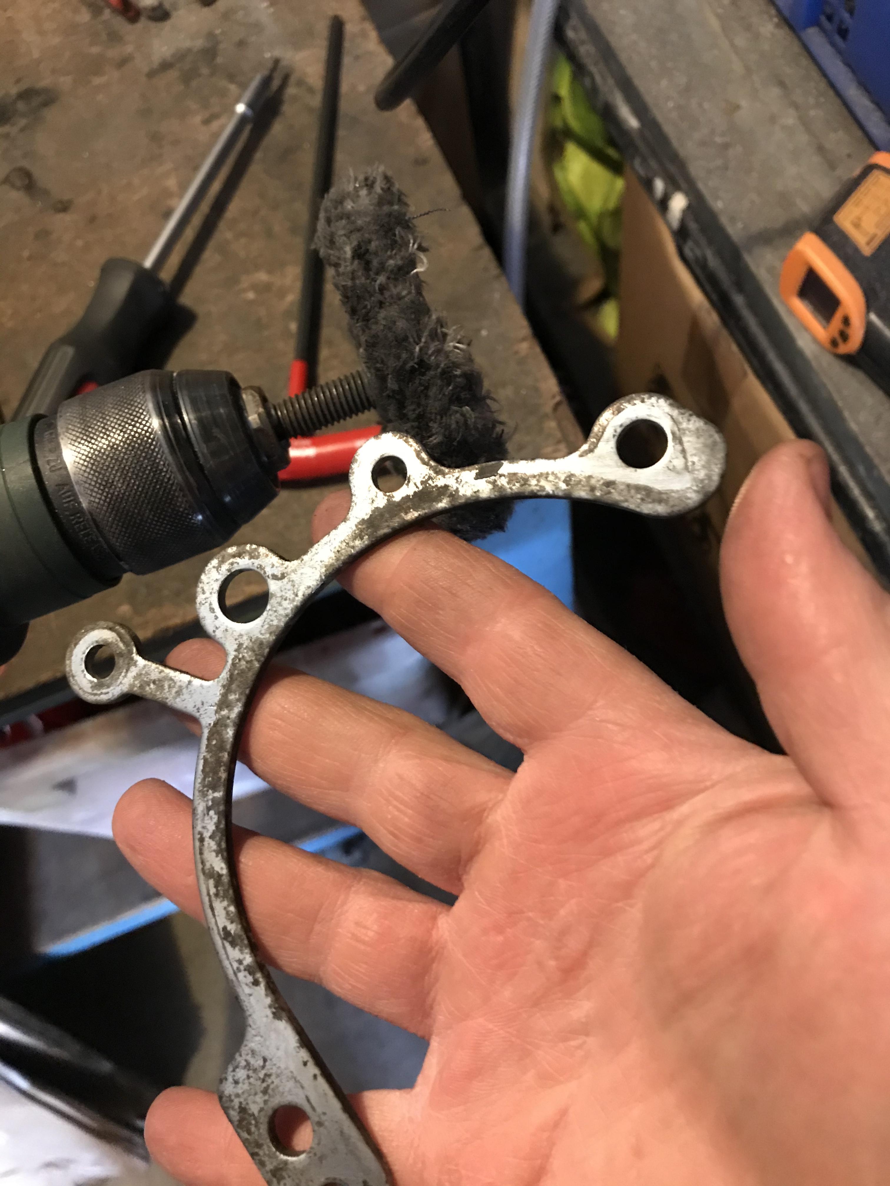
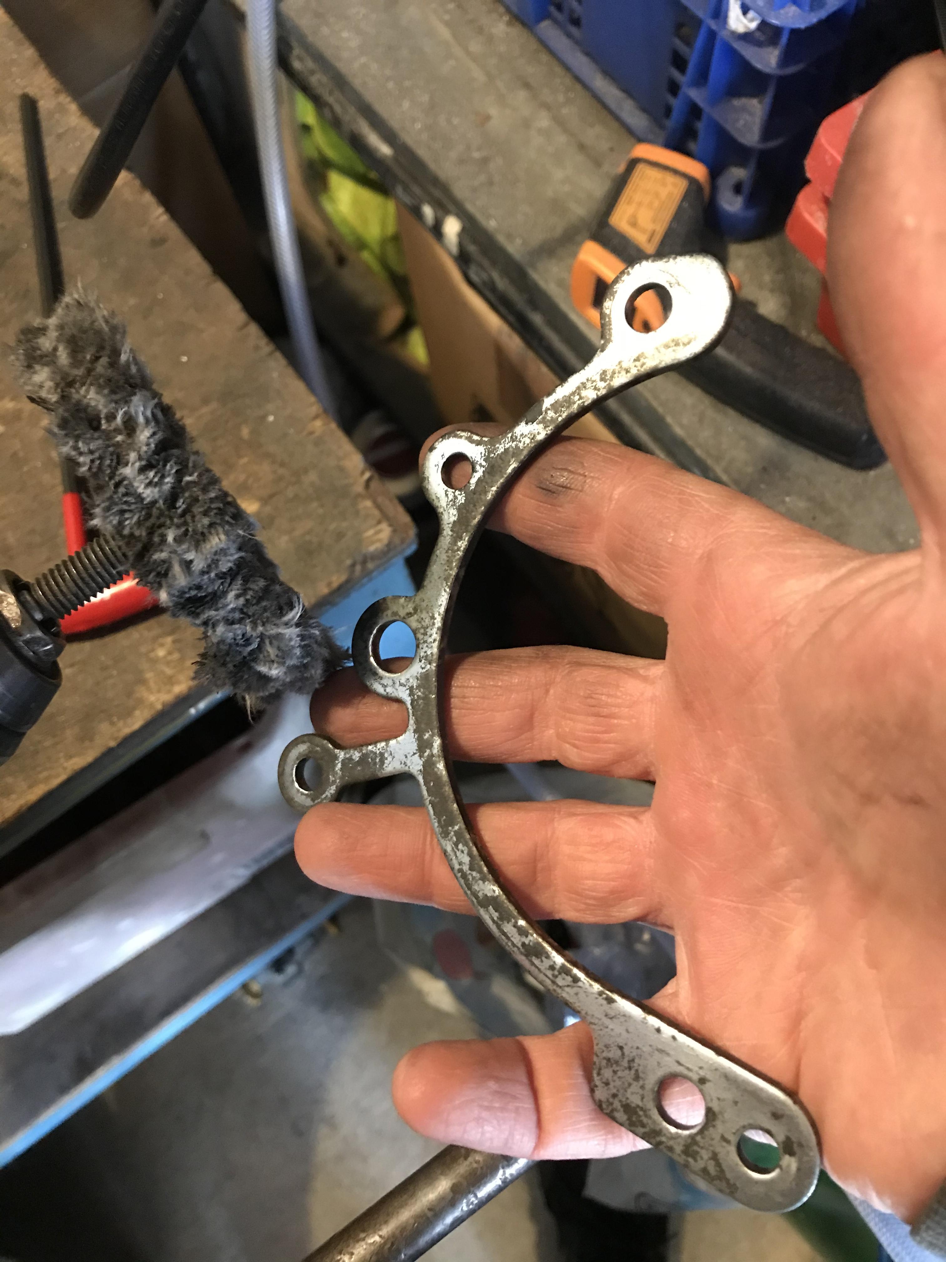
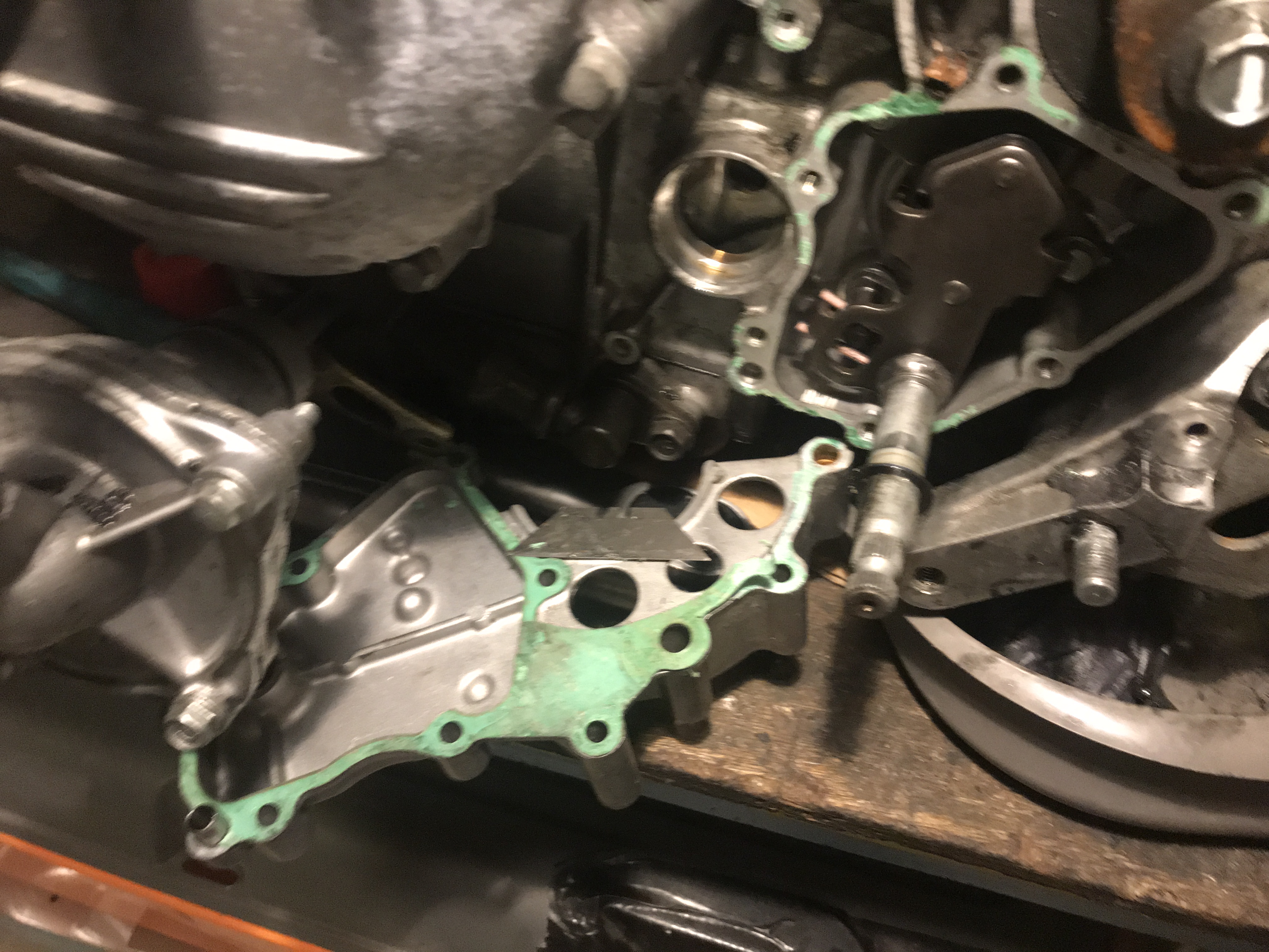
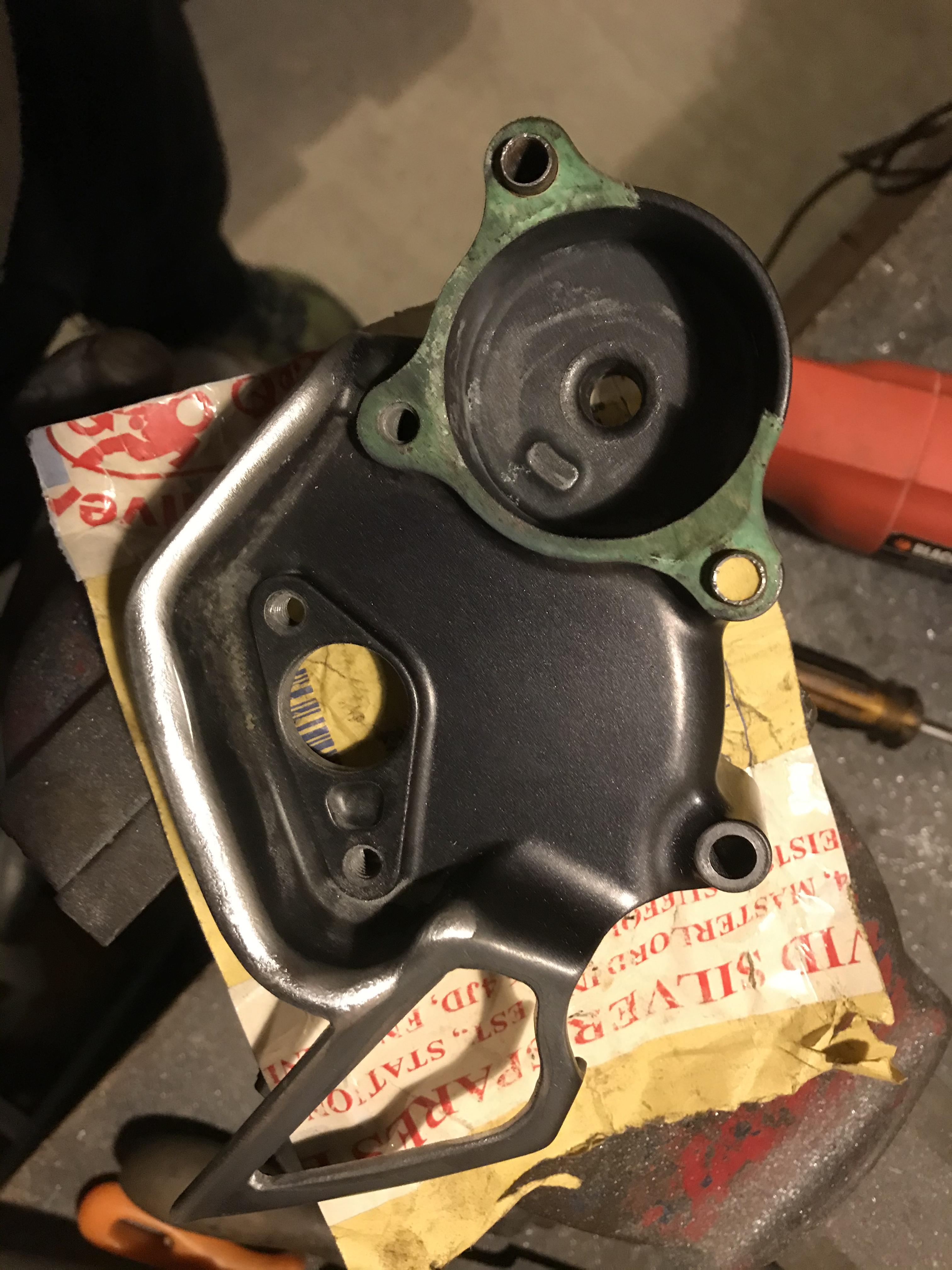
Thanks for the input, gents. Every day is a school day. Amazing how a build lets you get to know your engine better! Forgot to say I buffed the pitting out of the chain guide flange thingy (what’s this thing called?). Used a soft wheel on the drill and some fine compound to avoid burning through what’s left of the zinc coating. Before: After (it’s not the same - I promise!): Still looks rough but at least it’s smooth so the cases can mate together flush.
-
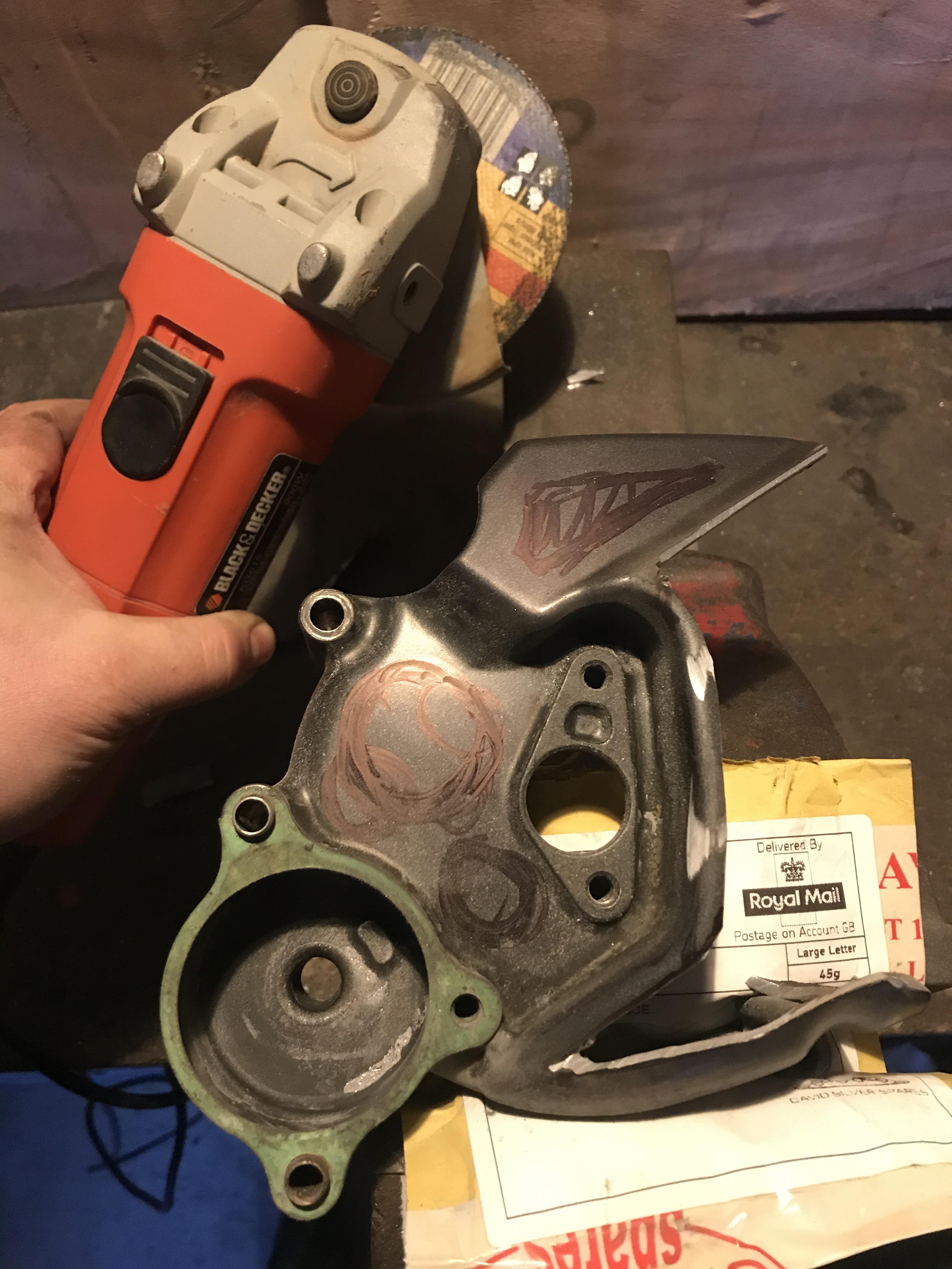
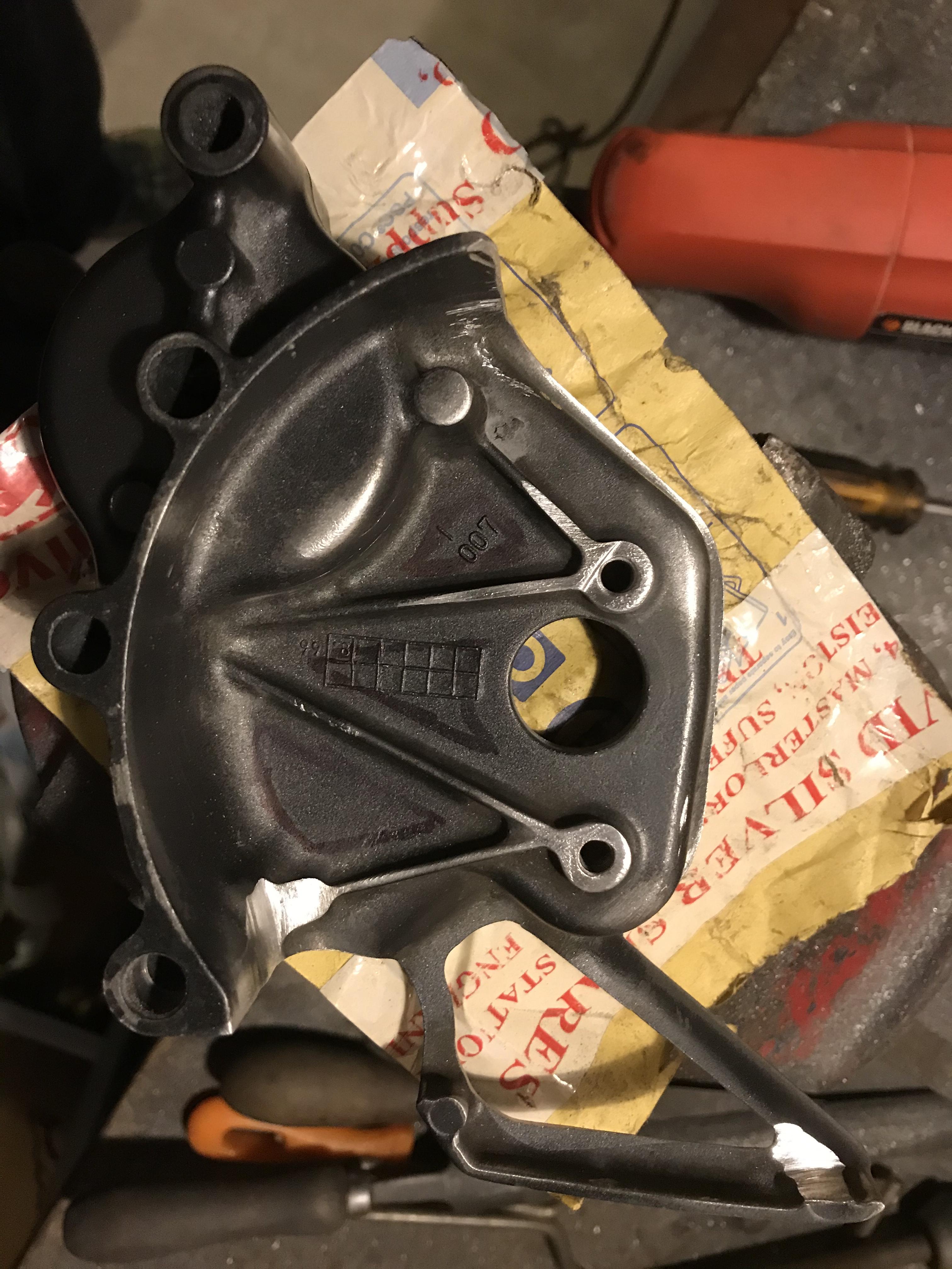
Time to cut down the sprocket cover. Had a spare in the shed and wanted to have a bit of fun tickling it with the angle grinder. Grinder got excited and tickled it too much - ended up taking off rather a lot more than intended. Not sure how it’s going to look on the bike but it is less than half the weight of an OEM. Was going to cut some of the central section away as per triangles marked out with sharpie but concerned about chain spatter so left it closed. Initial thought was to allow sprocket changes without removing the cover but position of speedo drive makes that impossible. Might go back to stock if I don’t like it. Let’s see...
-
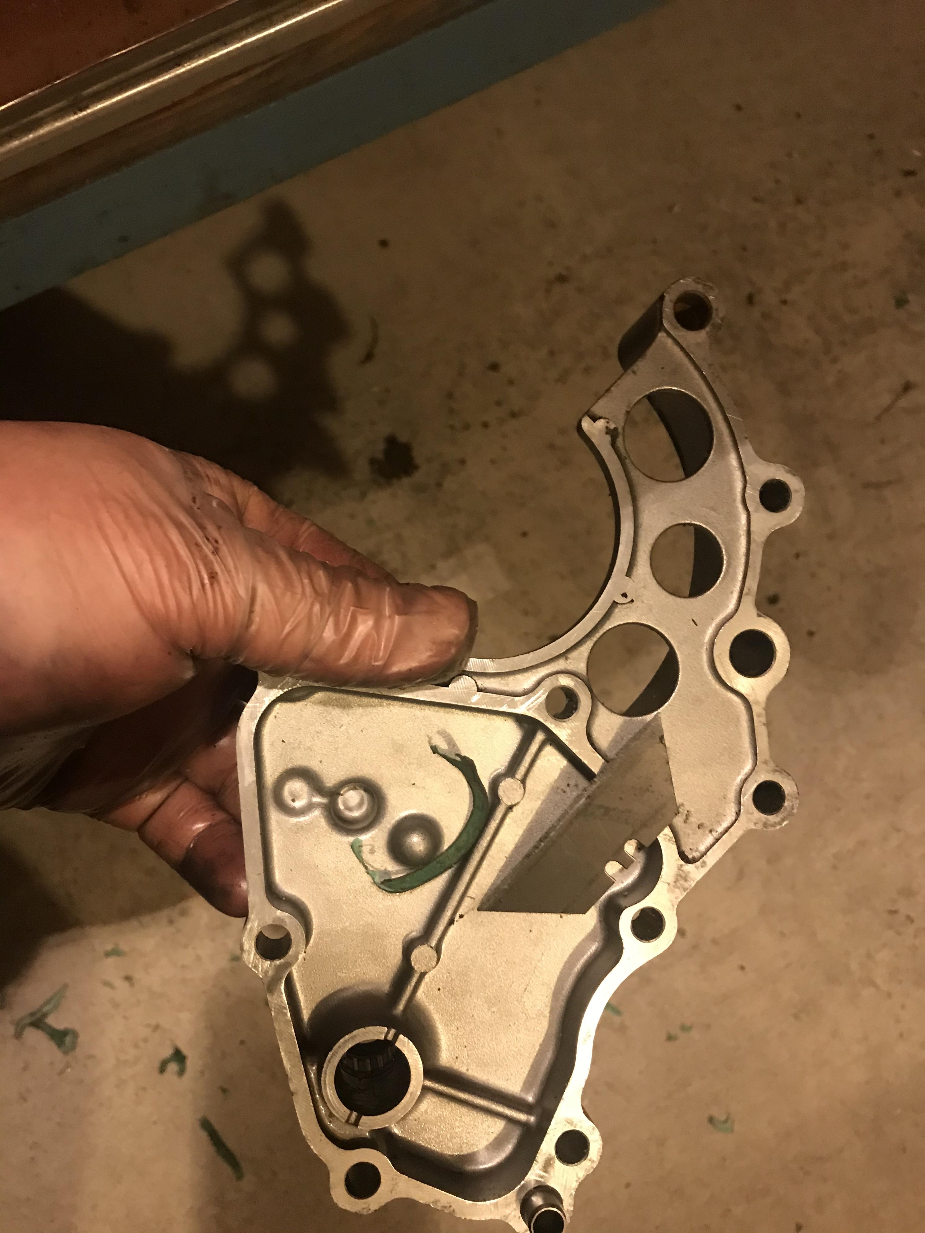
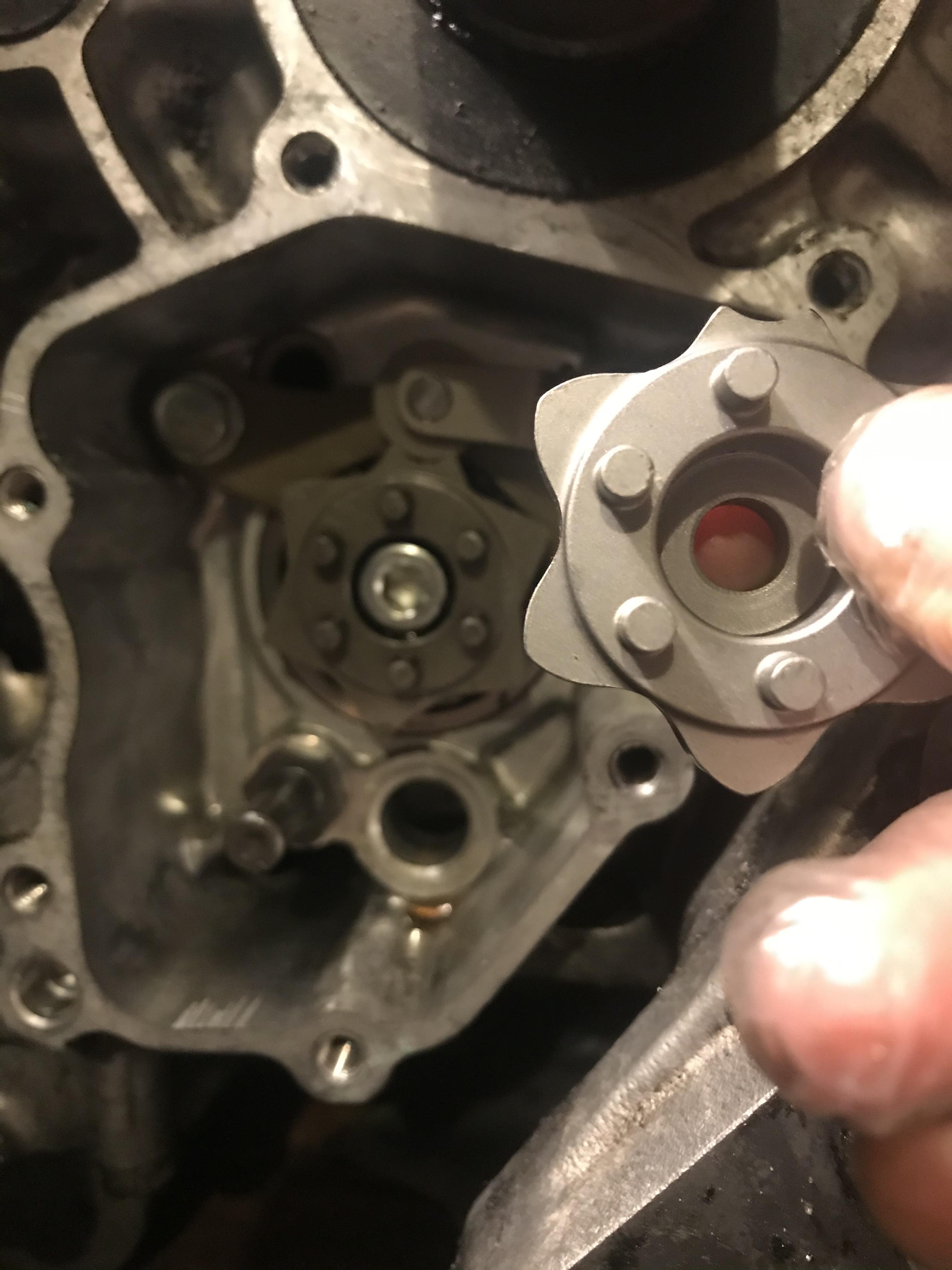
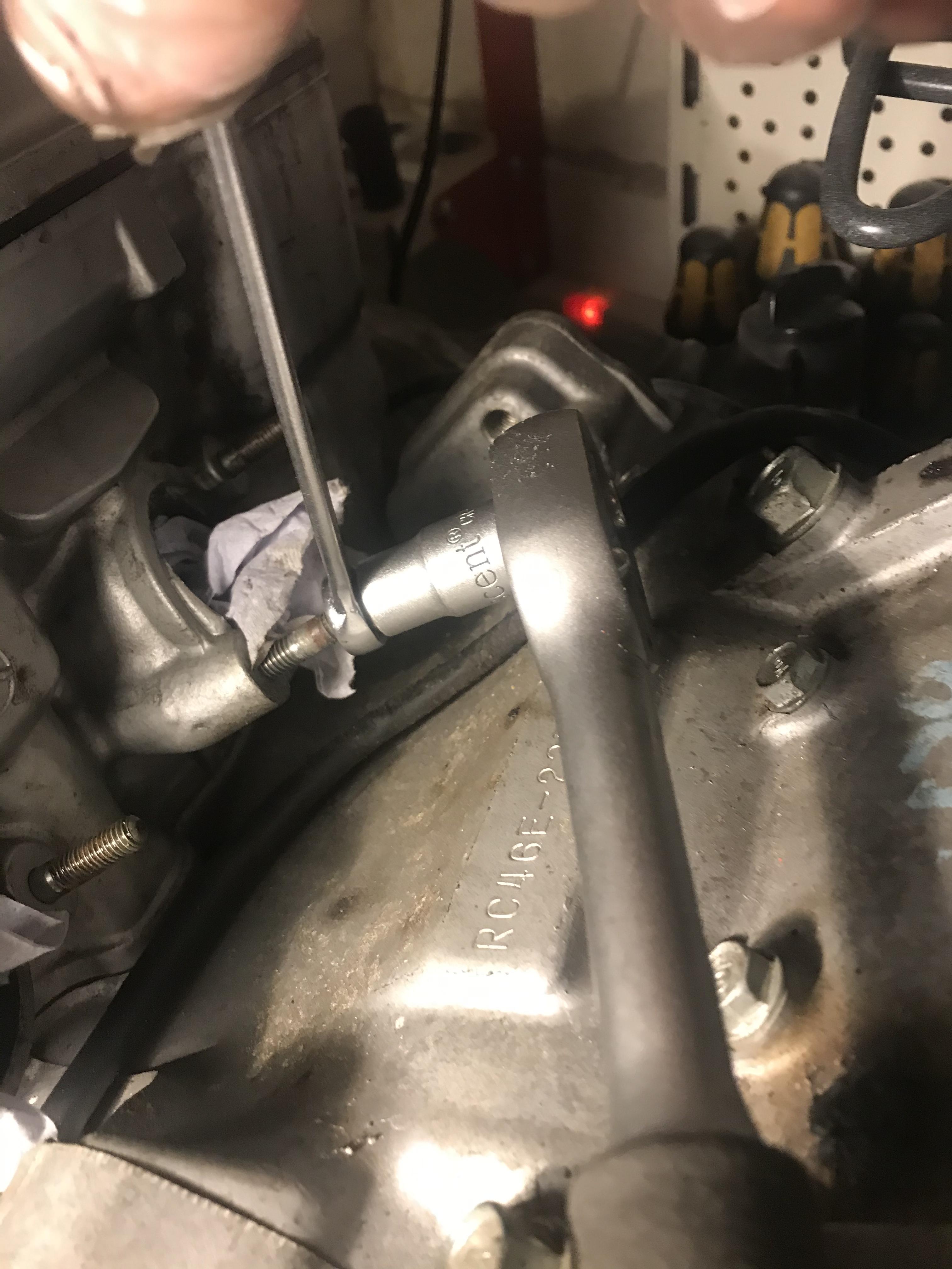
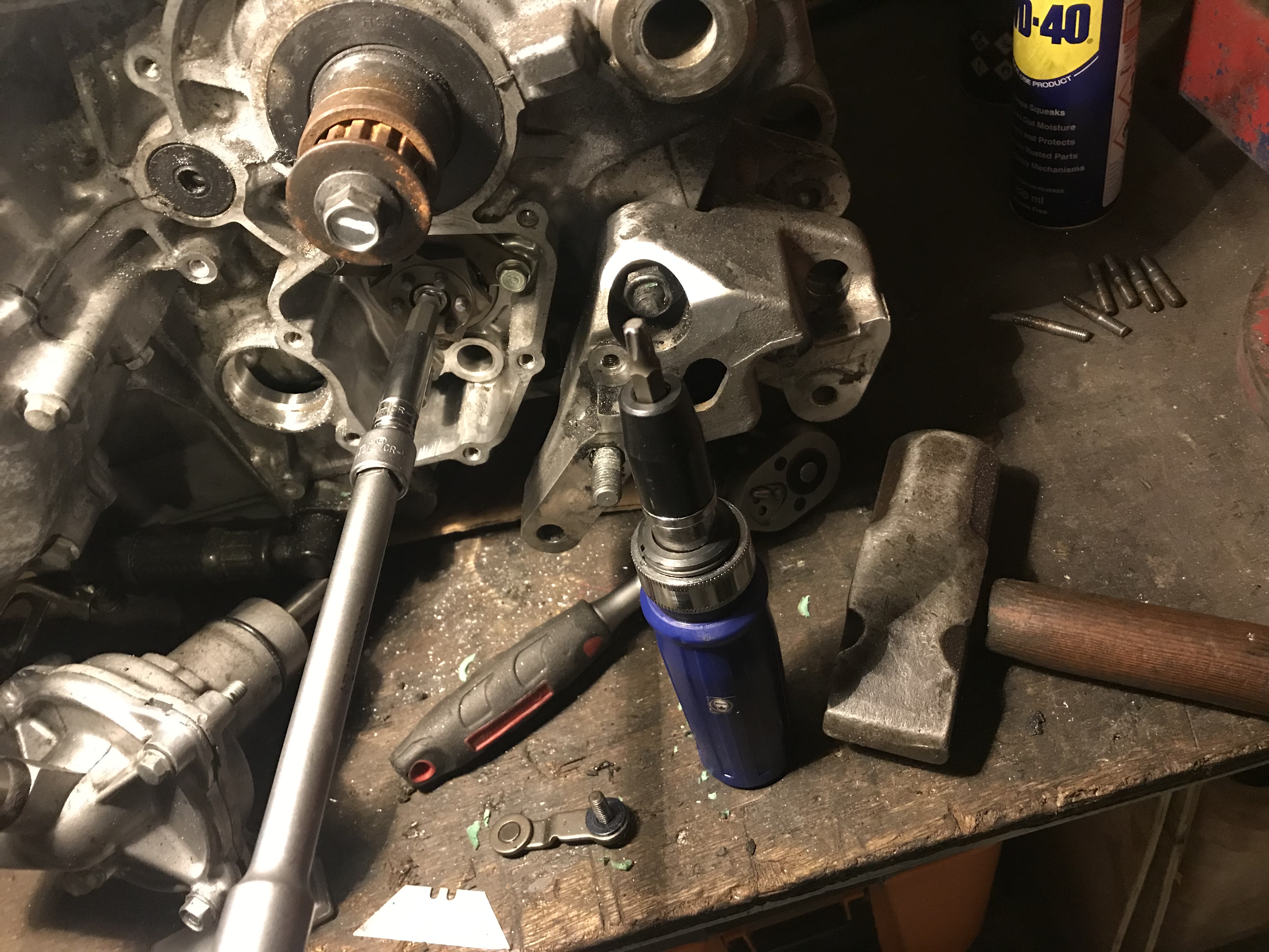
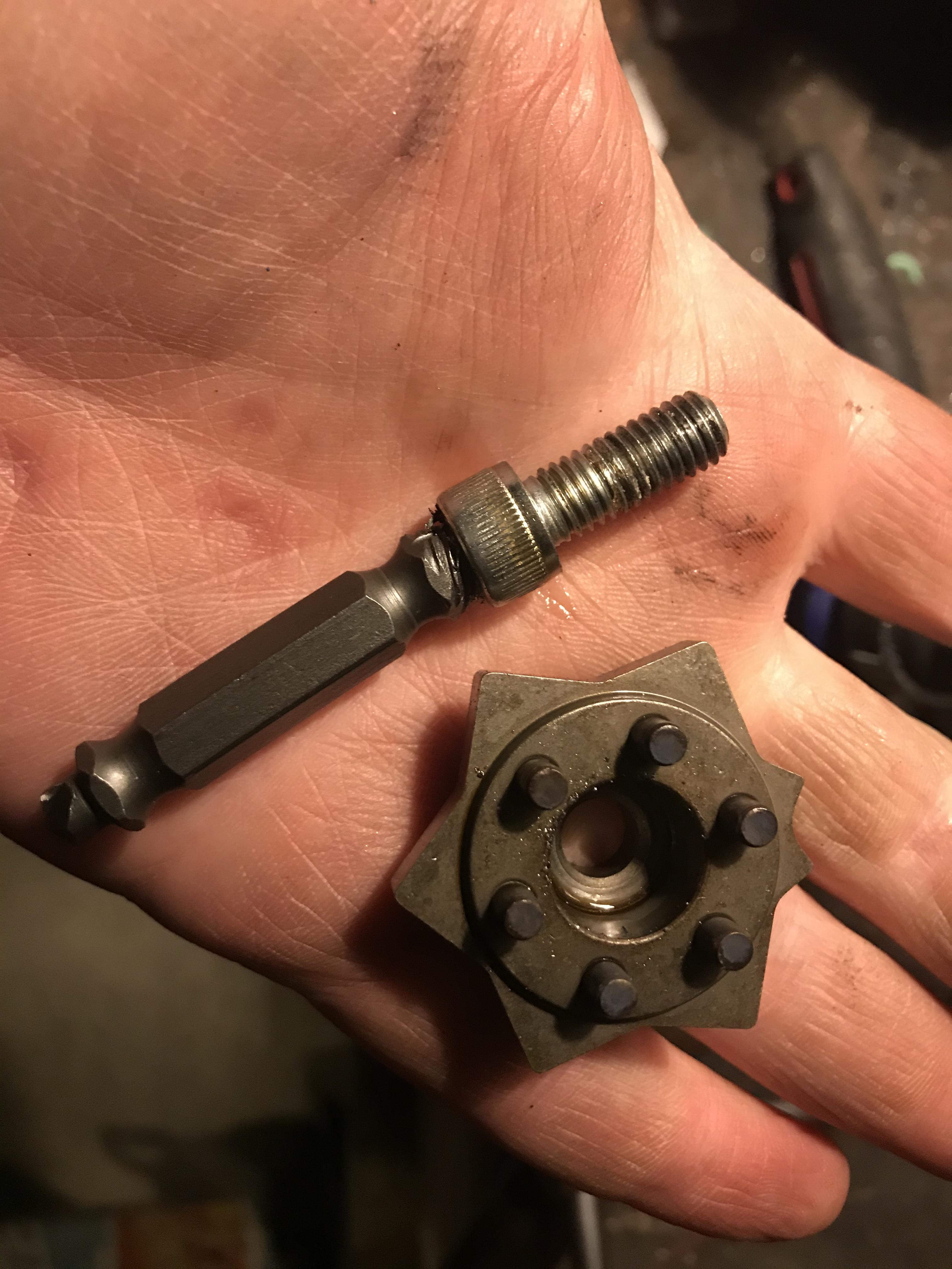
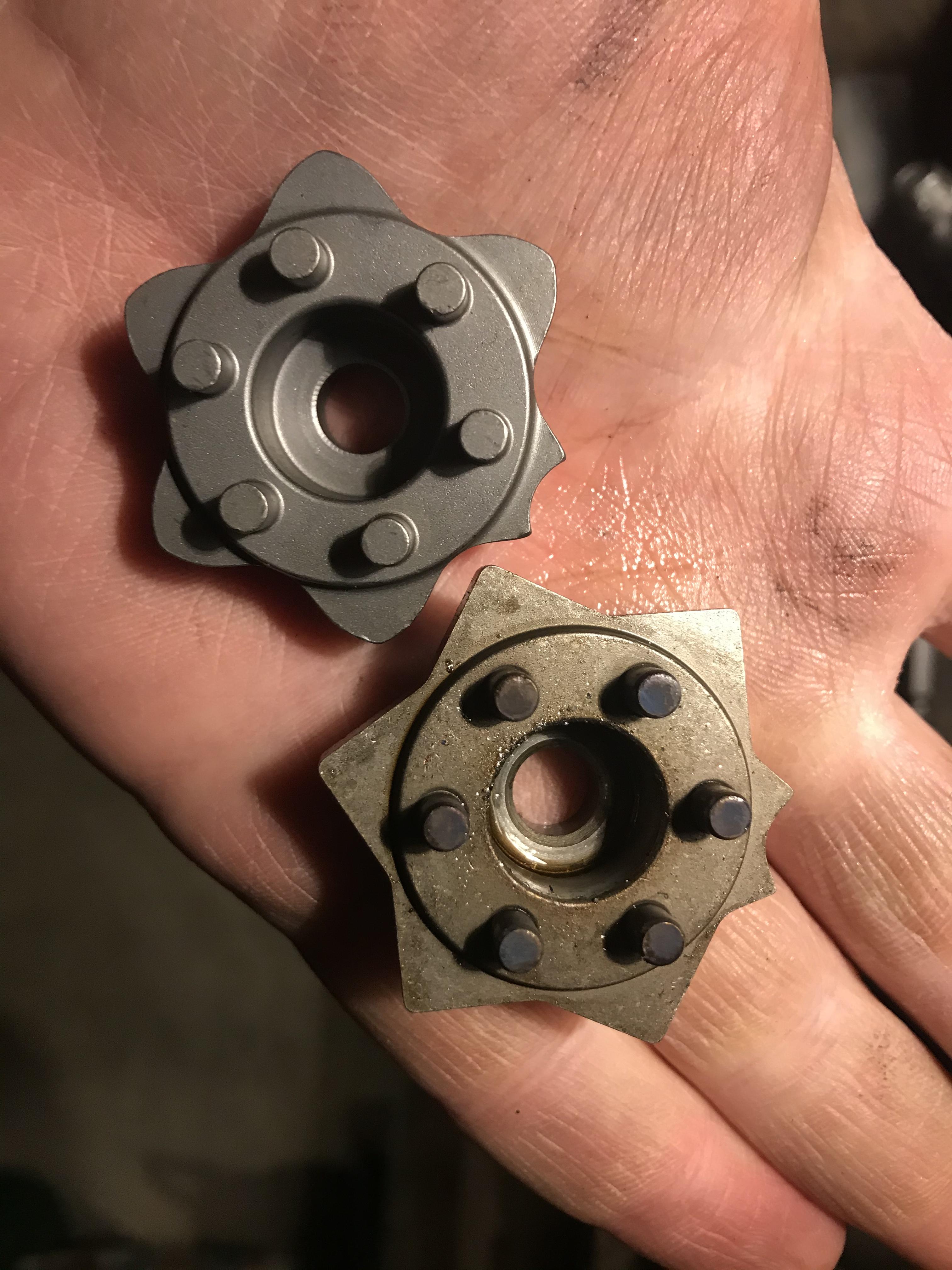
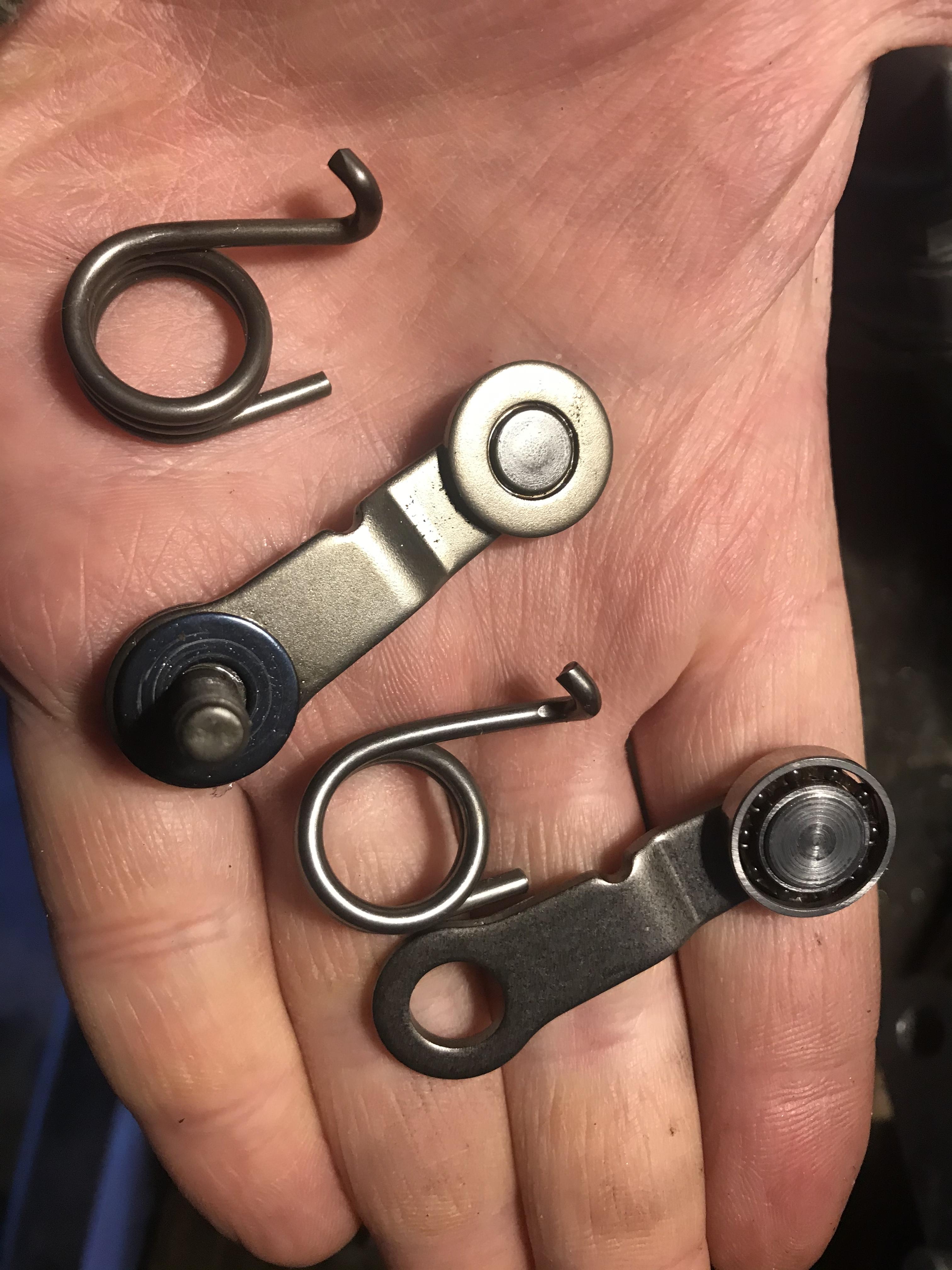
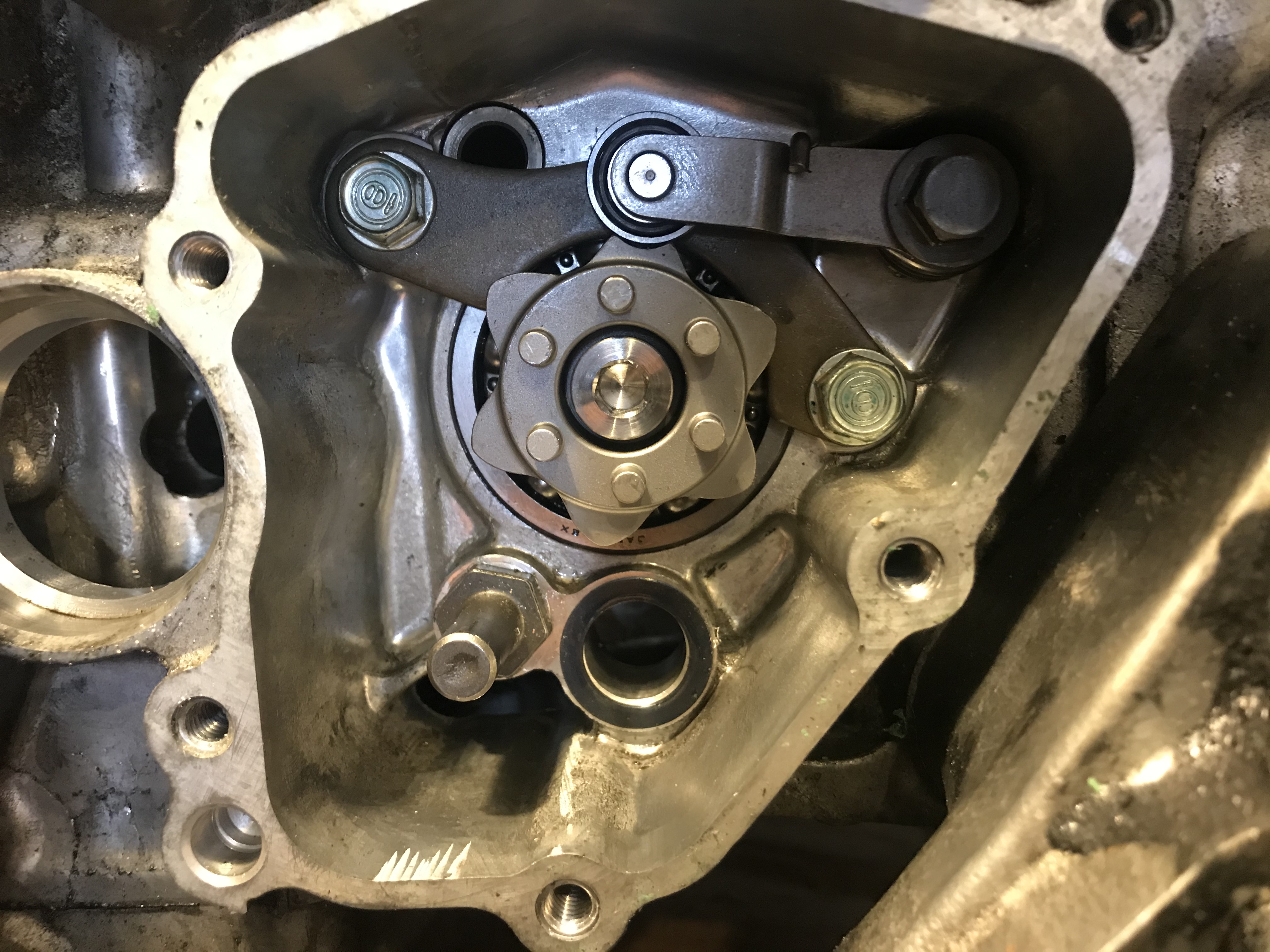
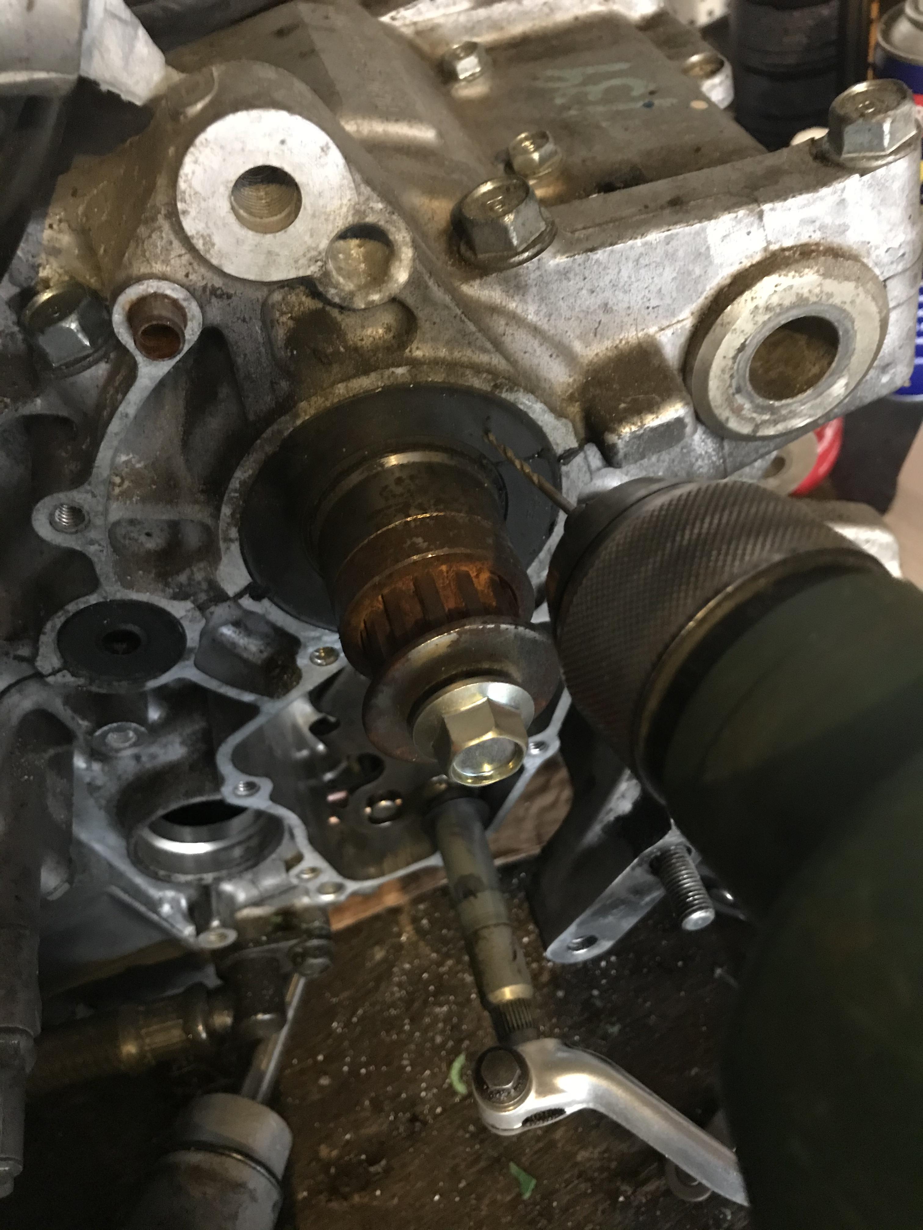
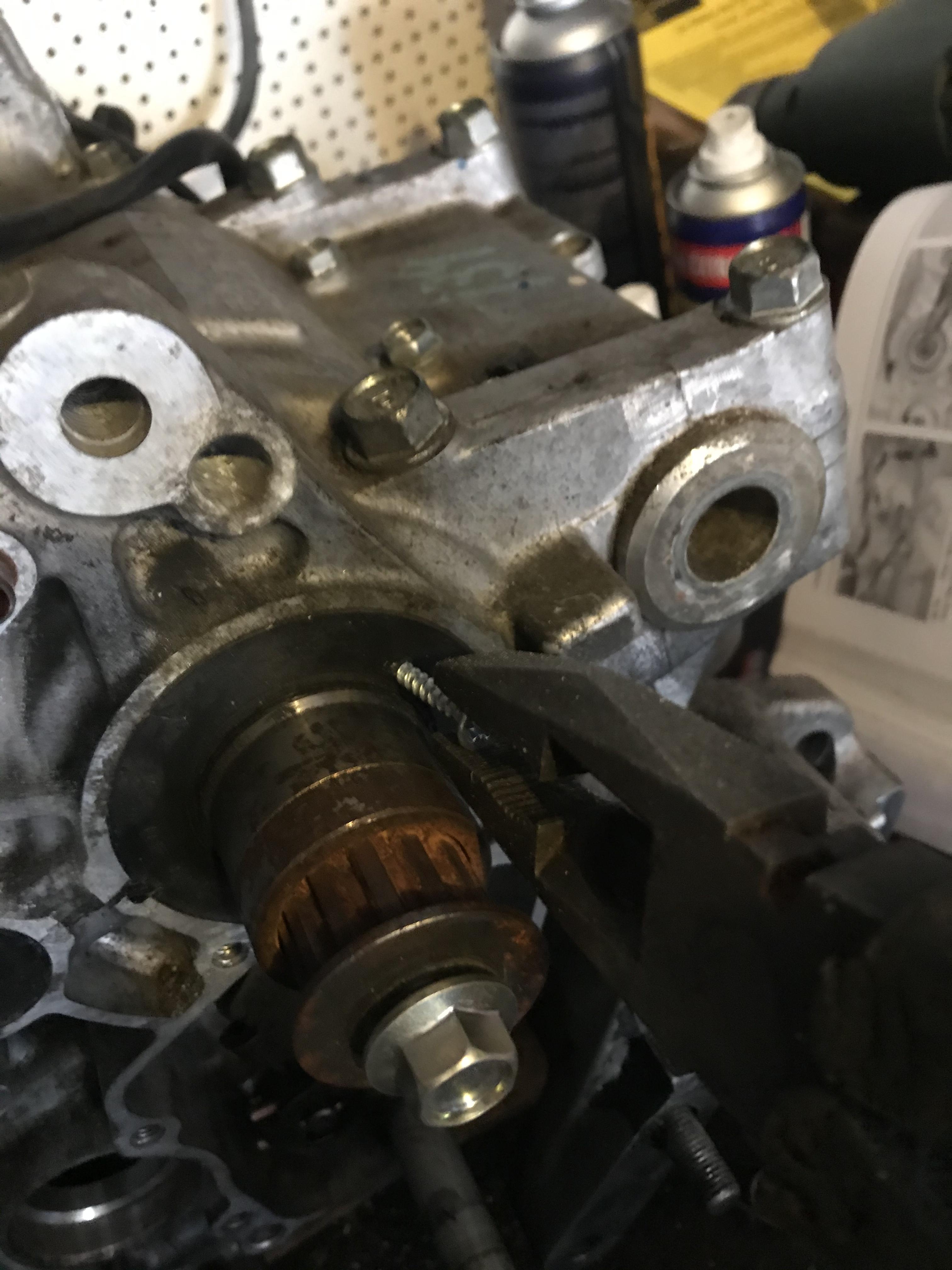
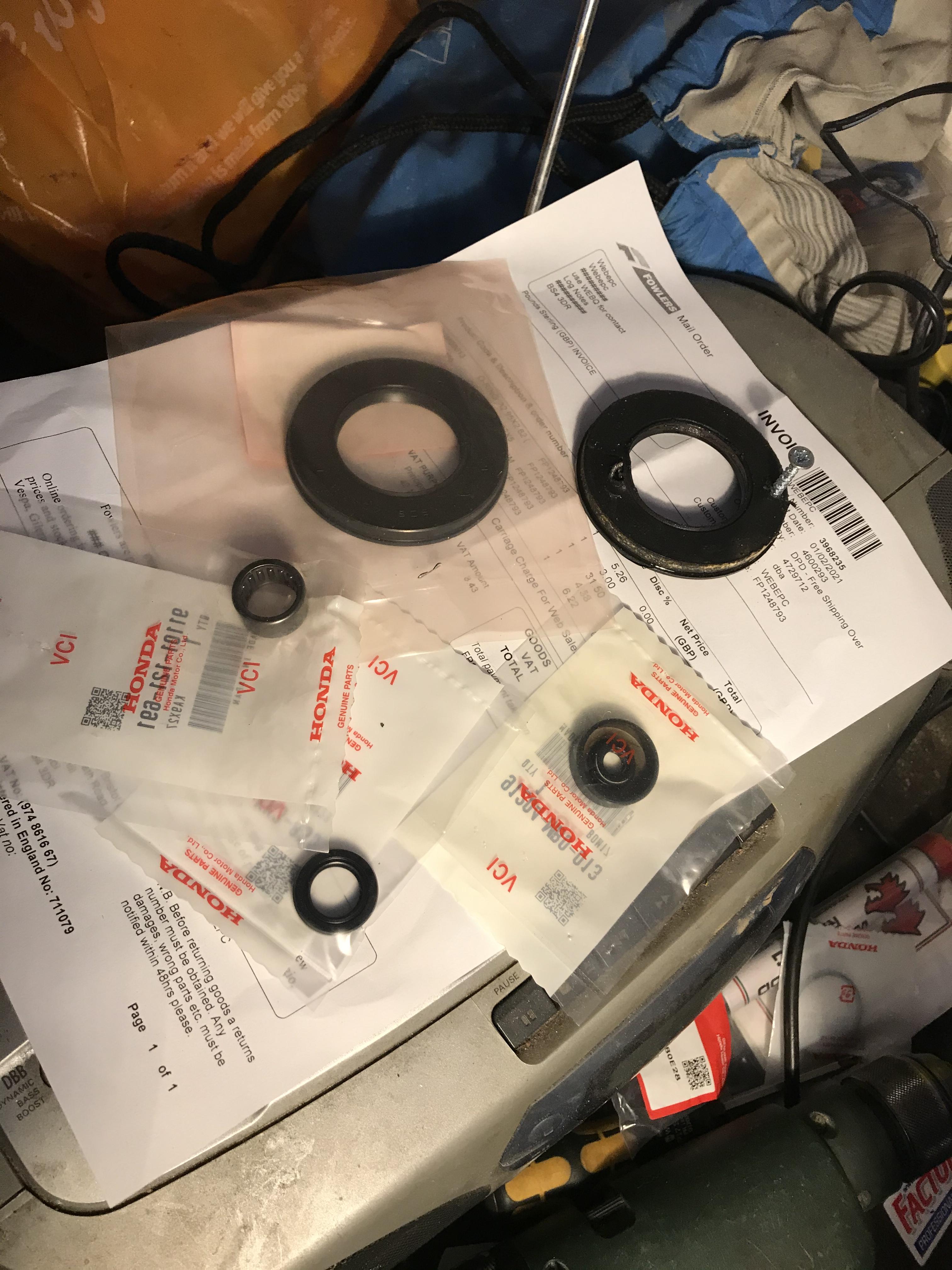
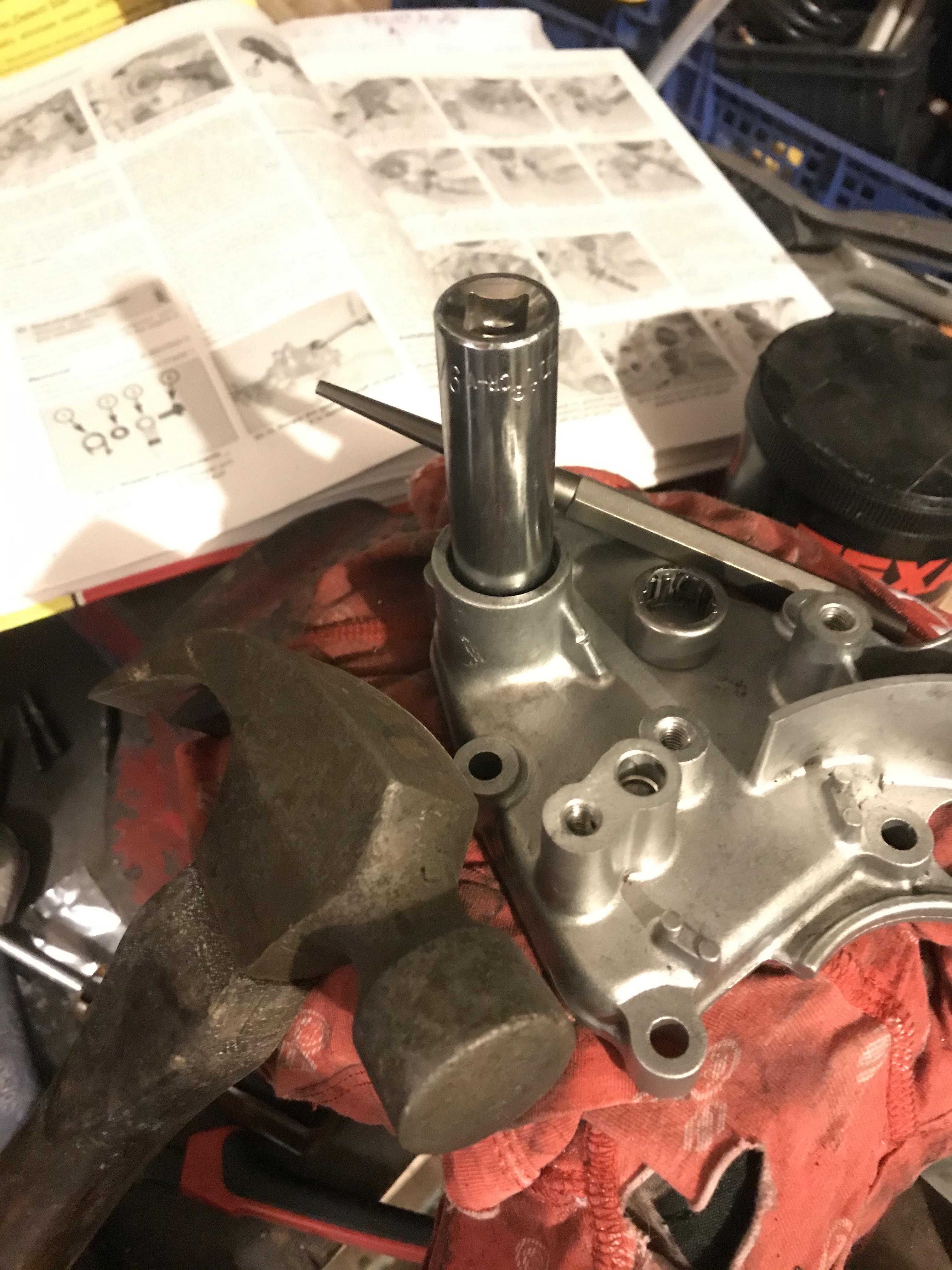
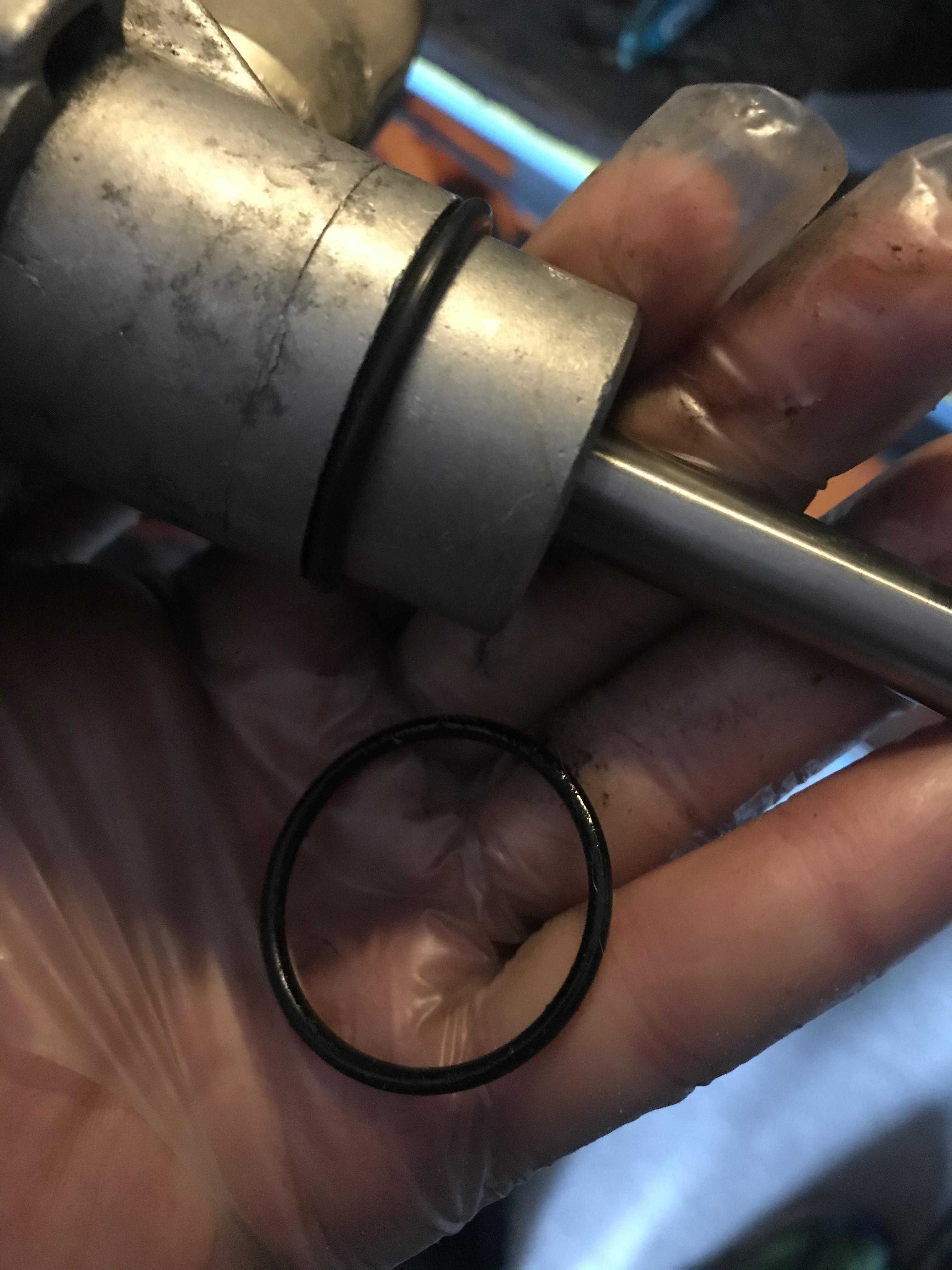
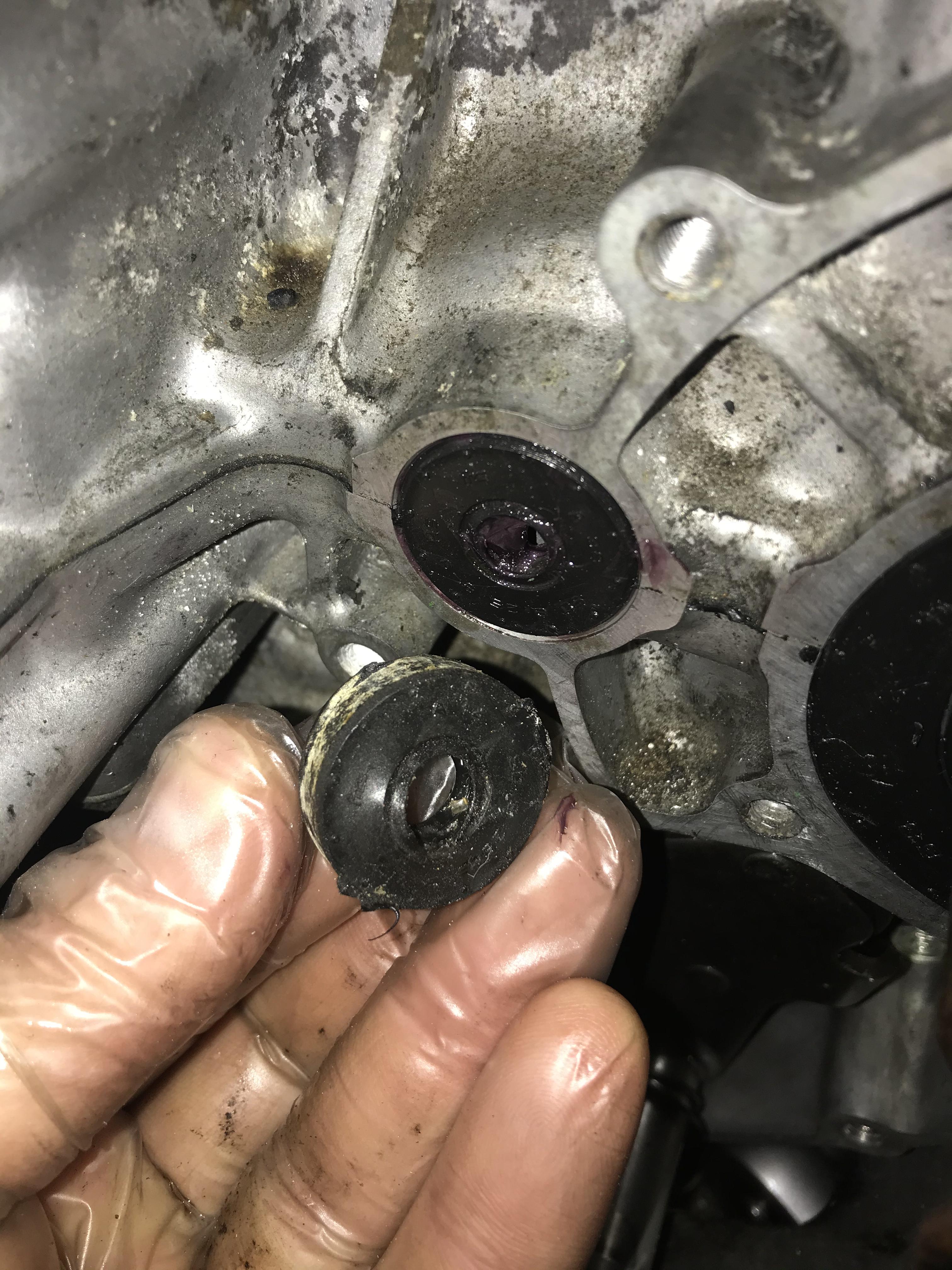
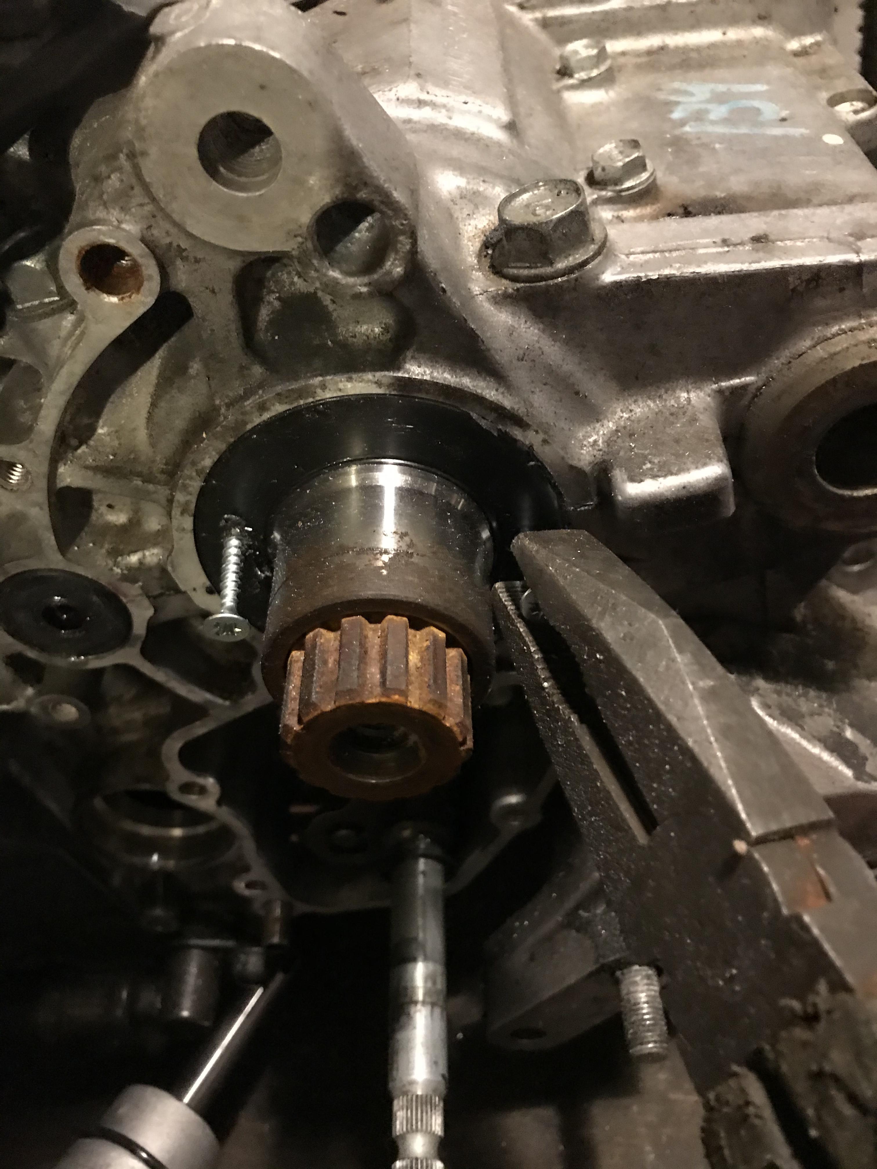
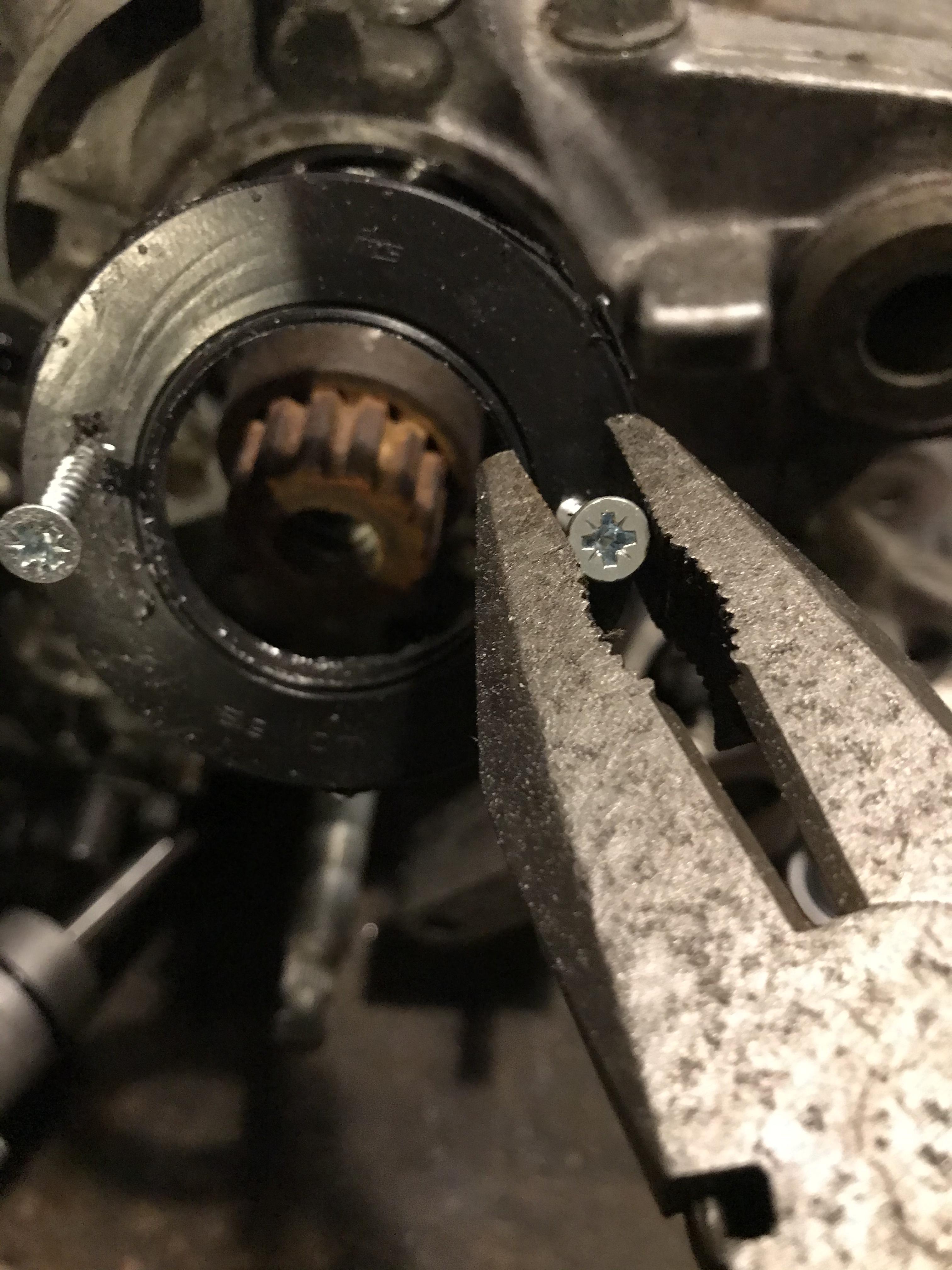
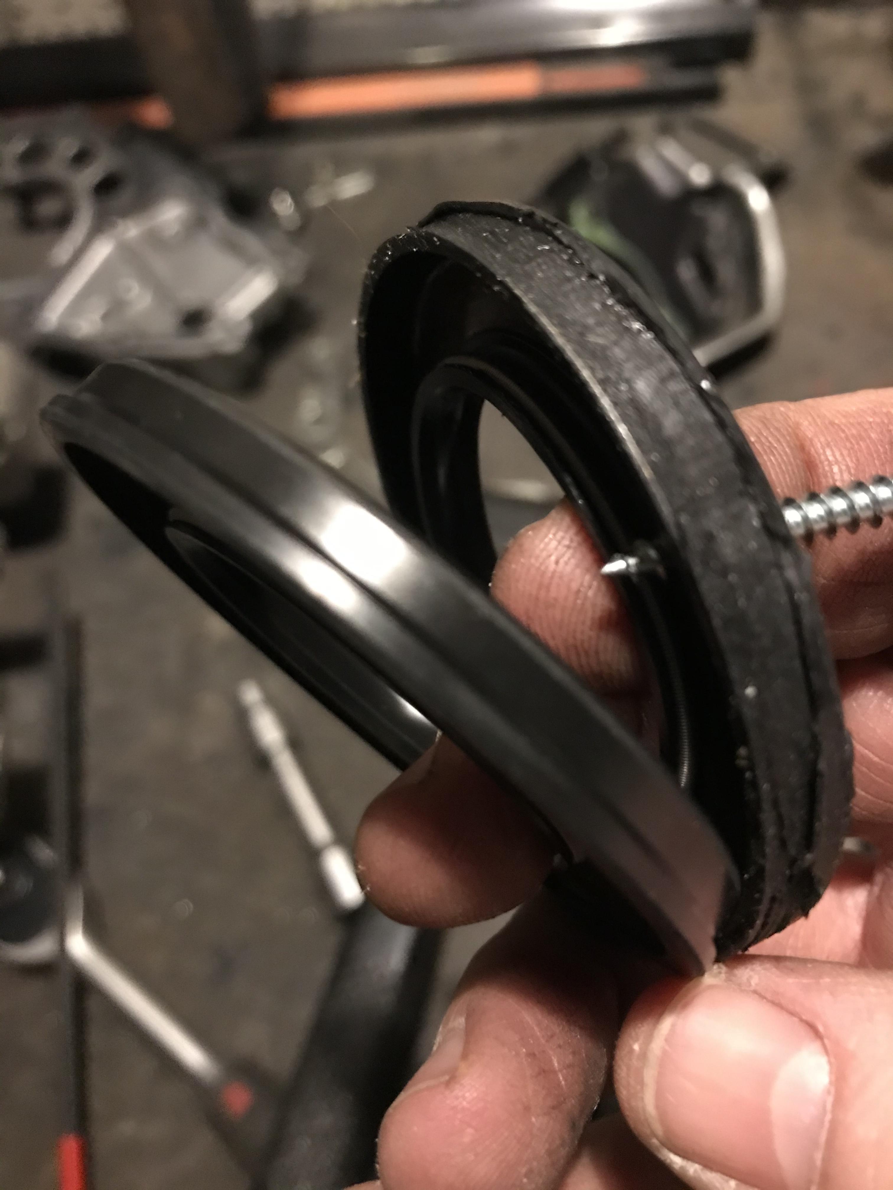
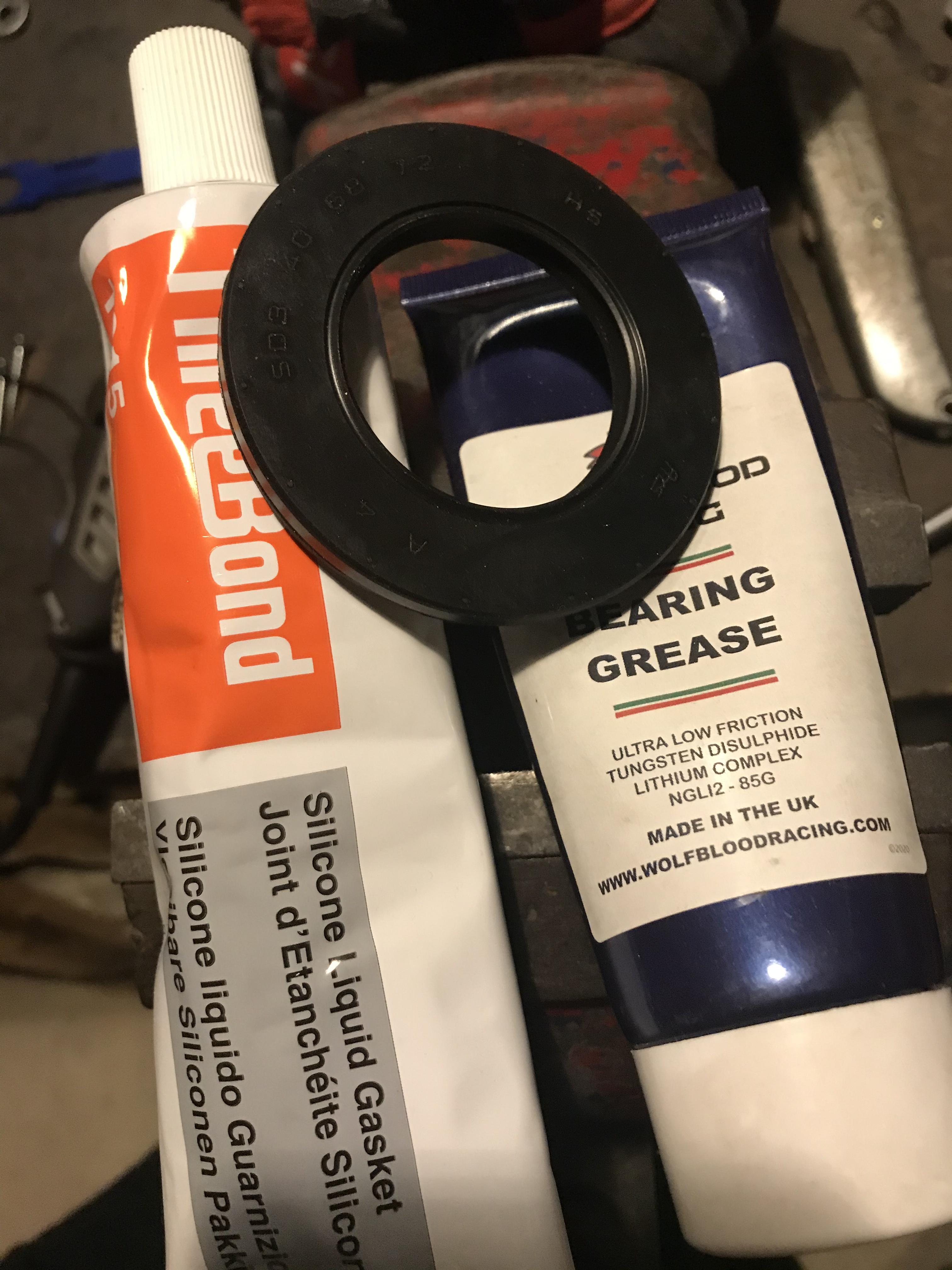
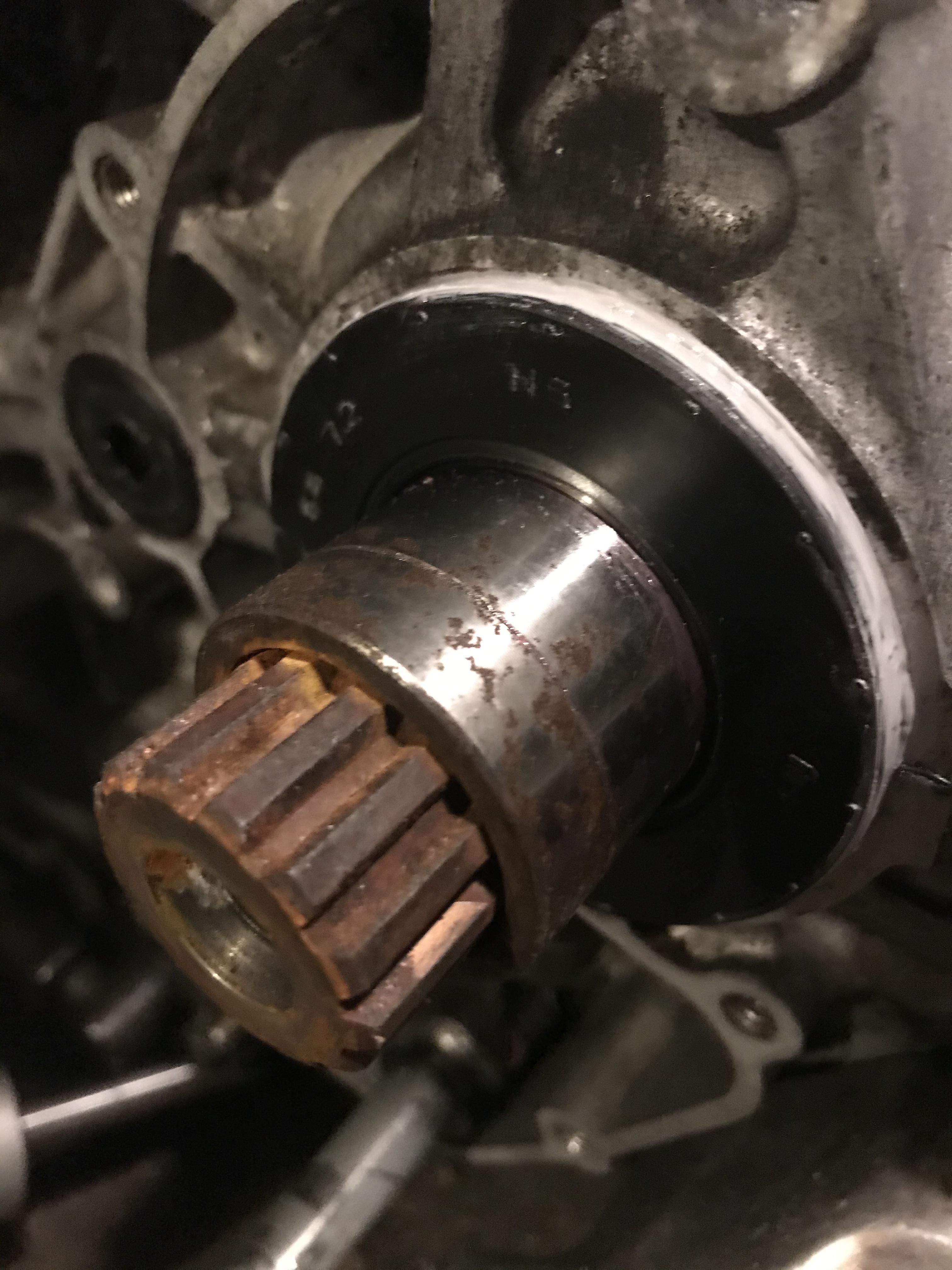
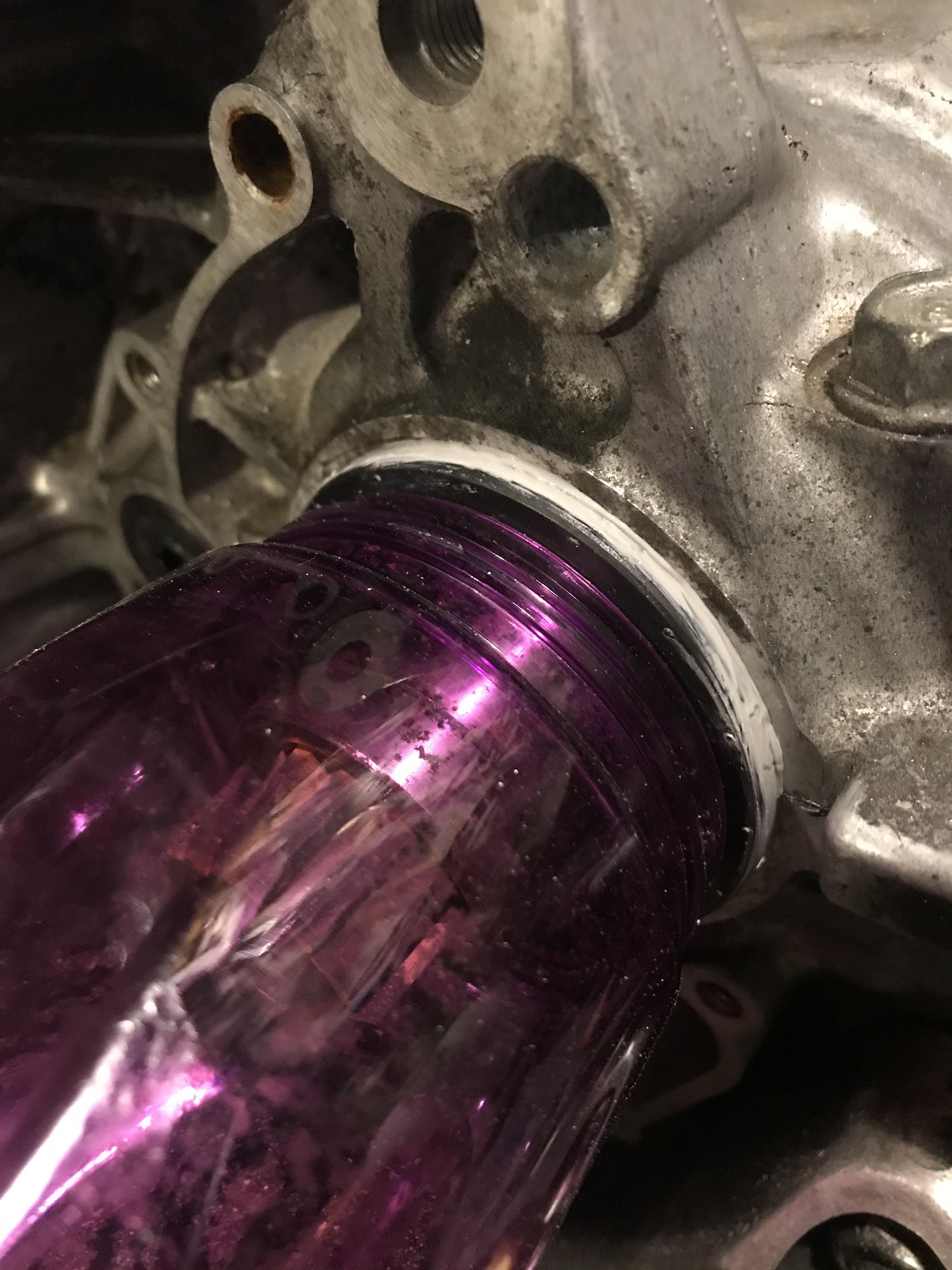
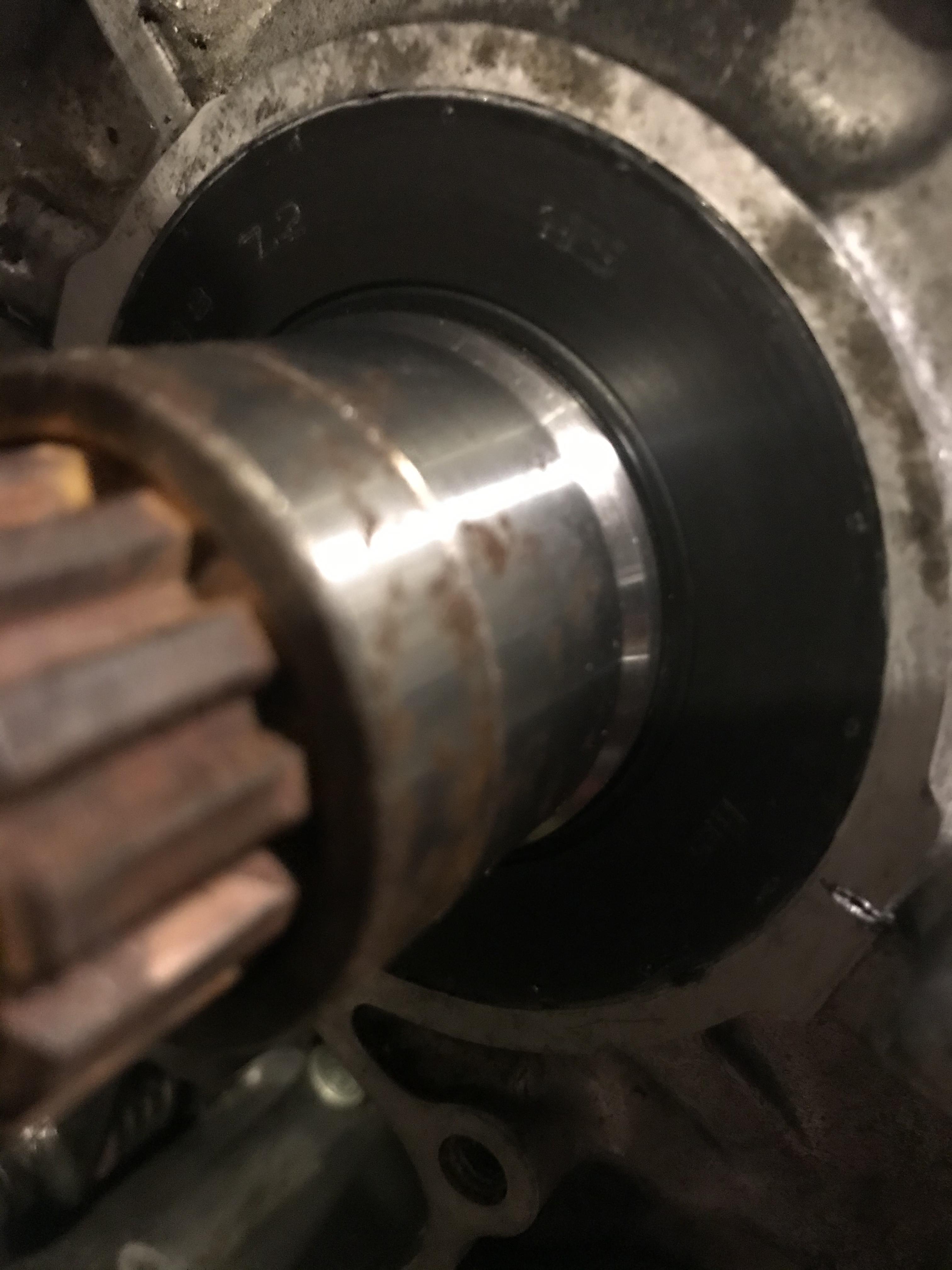
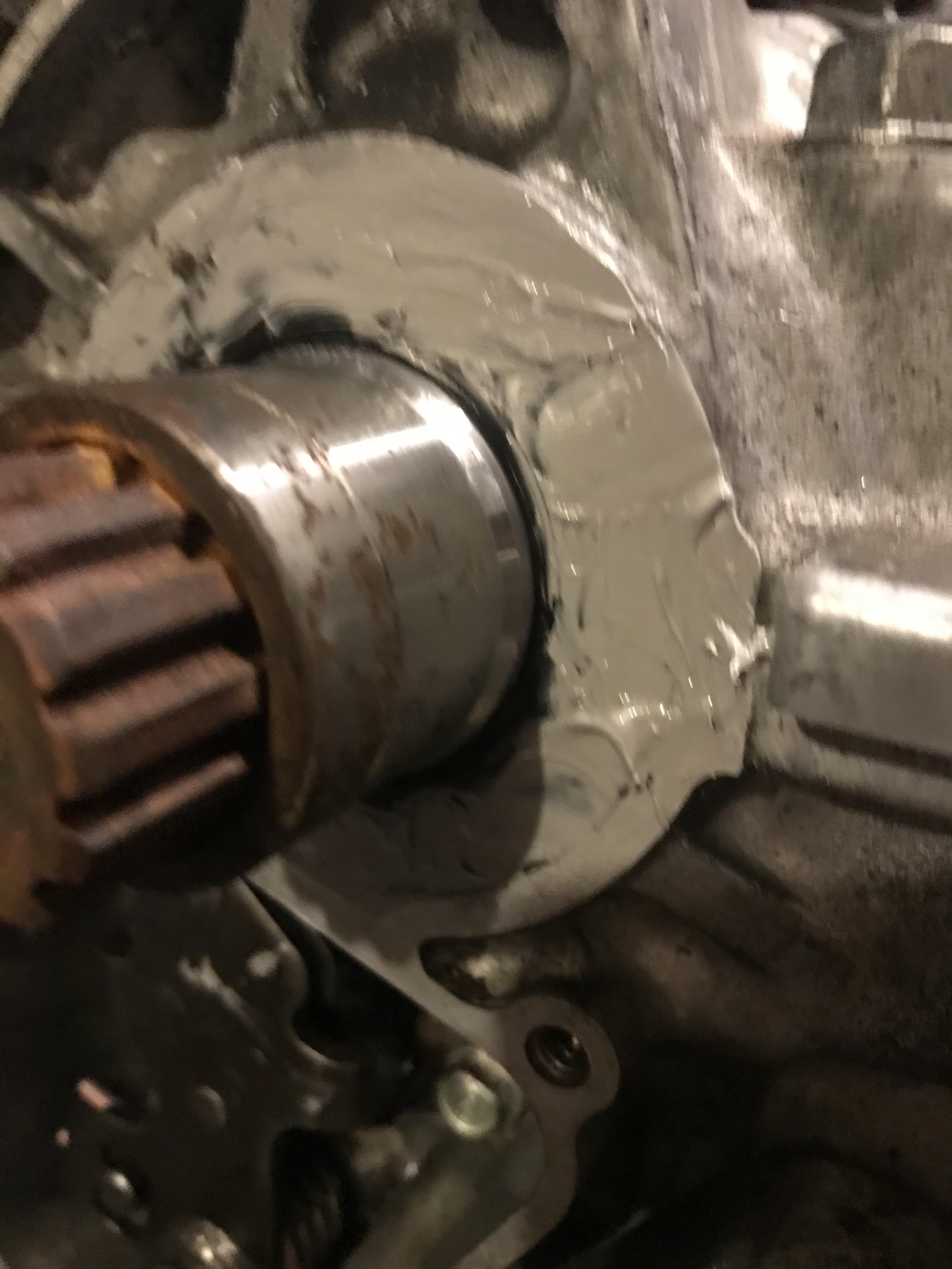
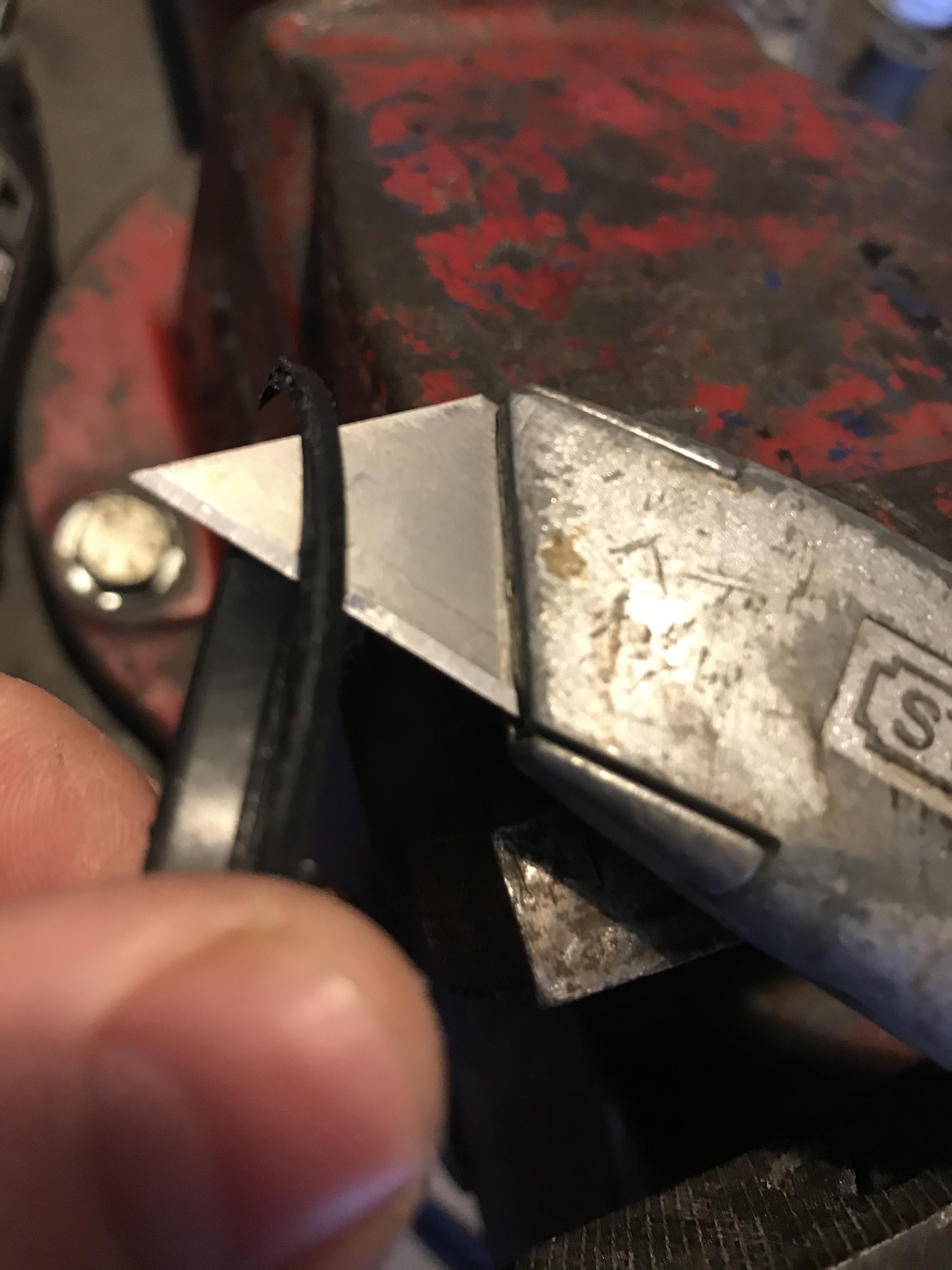
Last weekend I installed the Factory Pro shift star kit from the group buy I organised on here a couple years ago. Told you this was a slow project! Started by removing sprocket cover and shifter cover to access the star. Bit of chain grease, anyone? Nothing a bit of spray oil, brake cleaner and toothbrush can’t fix! Now the joy of gasket-scraping the shifter cover... Razor blade and patience to the rescue. Everything smooth so far...until that b@stard shift star bolt. Jesus that thing hates me! I used a brand new Bondhus hex key (best in the world), applied very smooth pressure and it still stripped. Then came the pain... Forced a hardened star key into the stripped hex with a hammer and cranked...no joy. Put a butane torch on its @$$ for a good while (forgot take pics as was “fuming” - ha ha ha!)...no joy Broke our the lump hammer and bolt extractor and went to town on it...no joy I was having visions of drilling off the head and using a stud extractor on the remainder. Getting quite angry now!!! So I reached for an old set of easy-outs as a last resort and mercifully the bolt gave way. Old OEM shift star in my hand next to the mangled bolt. Adding insult to injury, when ordering a new bolt I entered the wrong part number and got a sprocket bolt instead (I’ve already got 4 of those!). Anyway, it’s just a standard thread M8 bolt so I got a Ti one out the box, applied some thread lock and called it good. Comparison of OEM and Factory Pro shift stars below. Factory pro has rounded profiles and a little tab on the back so you can’t install it wrong. Comparison of OEM (top) vs Factory Pro (bottom) shift arm and spring. Springs look about the same but you’ll notice the FP has a ceramic bearing on the end instead of a plain bearing. Should make shifting smoother. All installed with Ti bolt, Loctite and a smear of grease. Time to replace all seals and bearings in this area whilst we’re here. New bearing and seal for shifter (pressed into shifter cover), new clutch push rod seal, new water pump o ring...and then it all went wrong when I changed the countershaft/sprocket seal. Socket used to drive bearing and seal home in shifter cover. Old bearing on the side fir reference - had to be smashed out with cold chisel and hammer. New o-ring for water pump. New clutch pushrod seal. My pain with the sprocket shaft seal is documented in another thread. The forum helped save this engine! If you’ve missed that thread the seal in question has an inner lip that can’t be pressed in from the outside. You need to split the cases and fit it from the inside - CRAZY! Don’t replace this sea unless you HAVE to. It’s not suitable for preventative maintenance. If you HAVE to get it out, drill a 3mm hole into the top (careful not to drill the bearing behind it - there’s about 10mm of space), twist a drywall screw into the hole and pull the seal out. I drilled two holes as the seal was tough to pull out. By pull I mean HEAVE like you’ve never heaved before. That lip makes it a real b@stard to remove. This pic shows a new seal on the left vs the seal I just tried to install from the right without removing the lip. Lip catches in the bore and peels backwards, ripping the outer part of the seal off as you drive it in. If you’re fitting this seal from the outside just trim the lip off with a sharp blade and press it in with some 3 bond to seal the outside bore. Or go one better and buy an aftermarket seal without a lip as it will slide in stronger without trying to peel off at the edges. Drive the seal in as square as possible to stop the outside pealing away. The 3 bond helps lubricate it for smooth entry. Used my wife’s water bottle as a driver. Seal seated with a sliver of 3 bond showing around the outside. Try to install the seal so it misses the wear marks made on the shaft by the previous seal. Then give it a smear of 3 bond on the outside to help seal it better. Ugly but it works and the sprocket will cover it anyway.
-
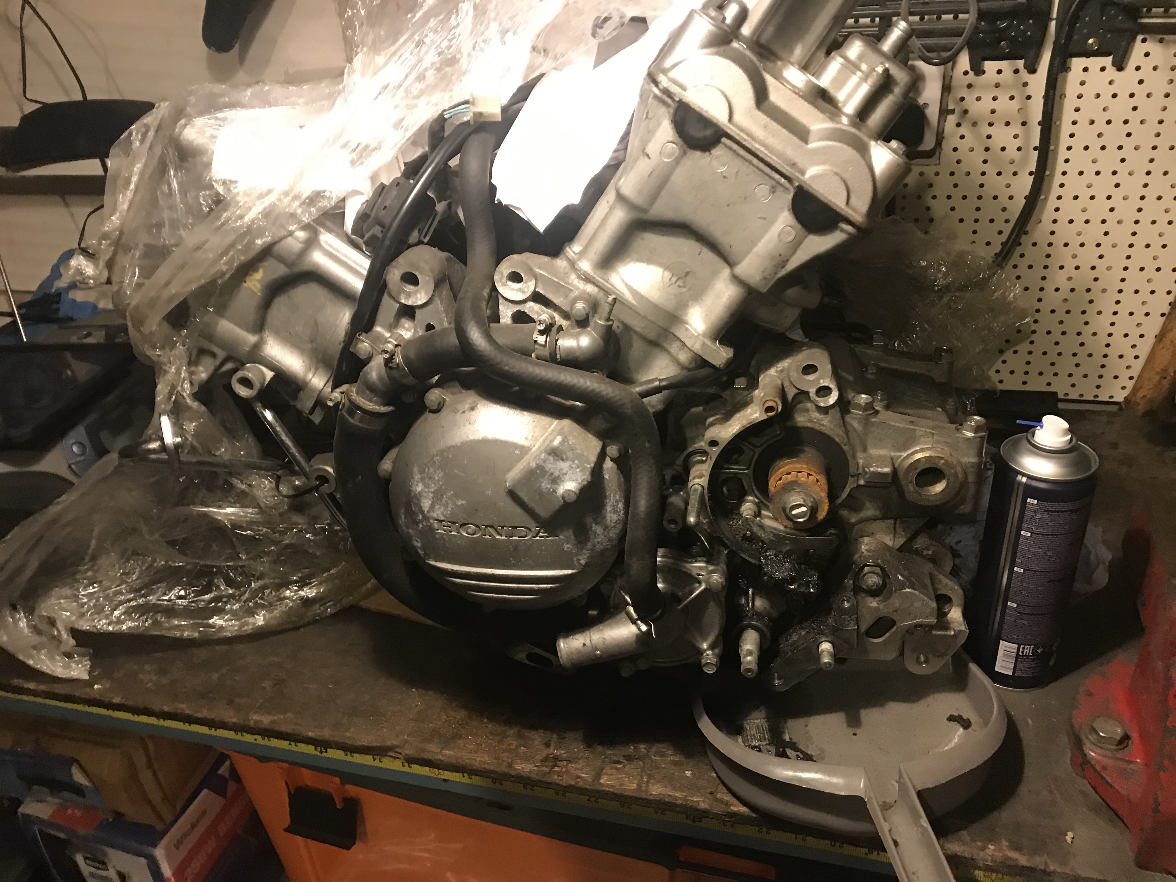
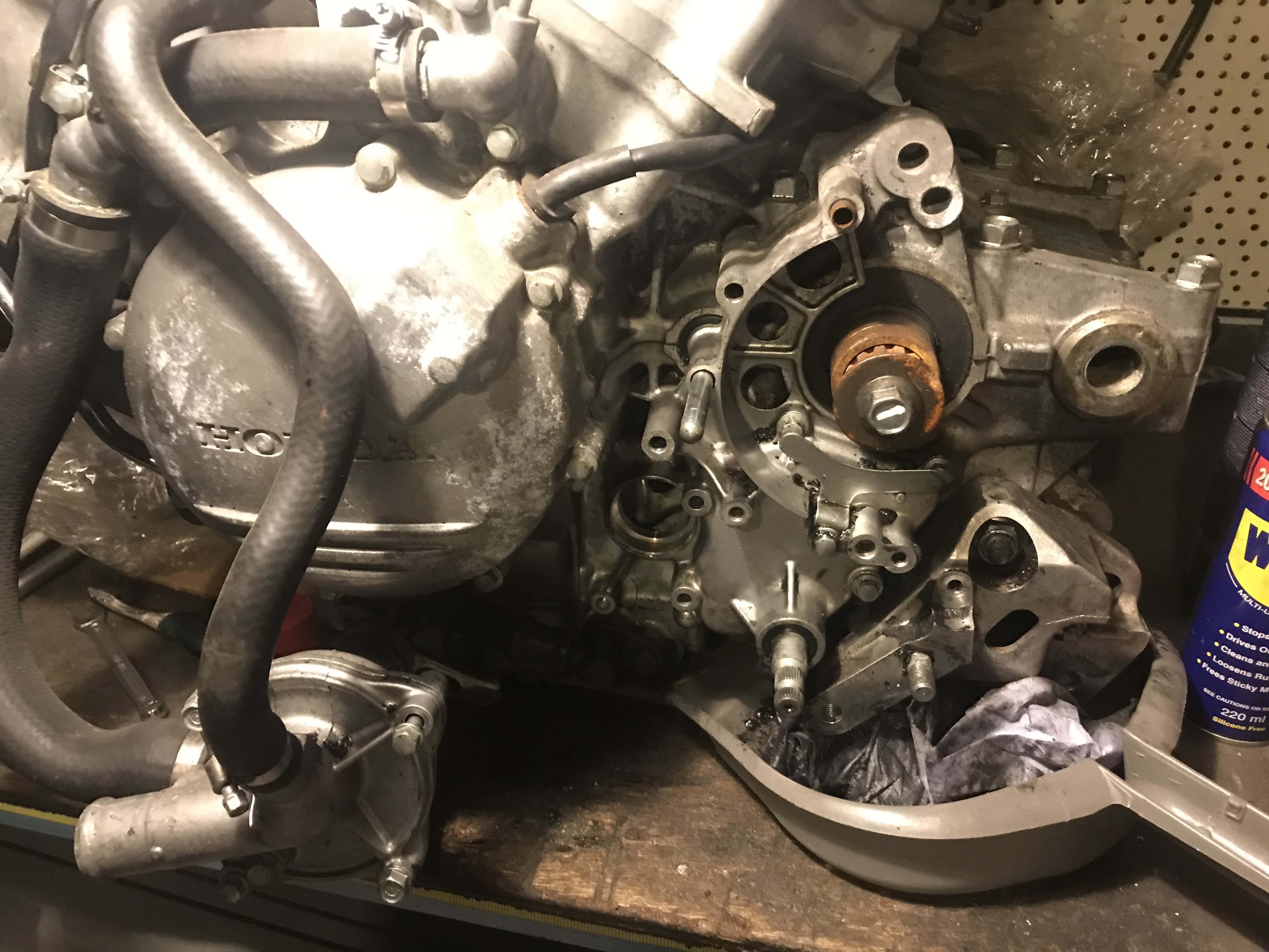
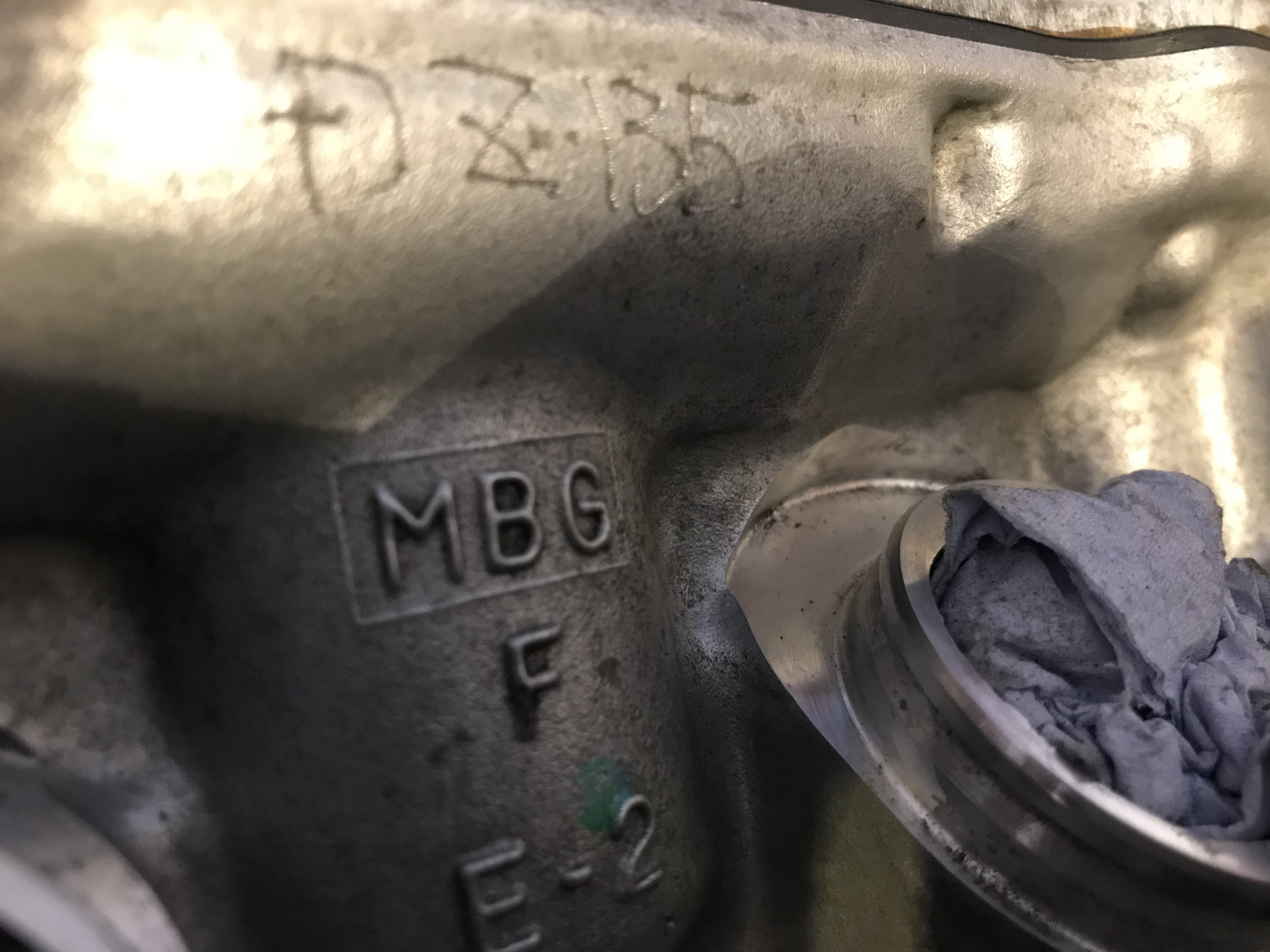
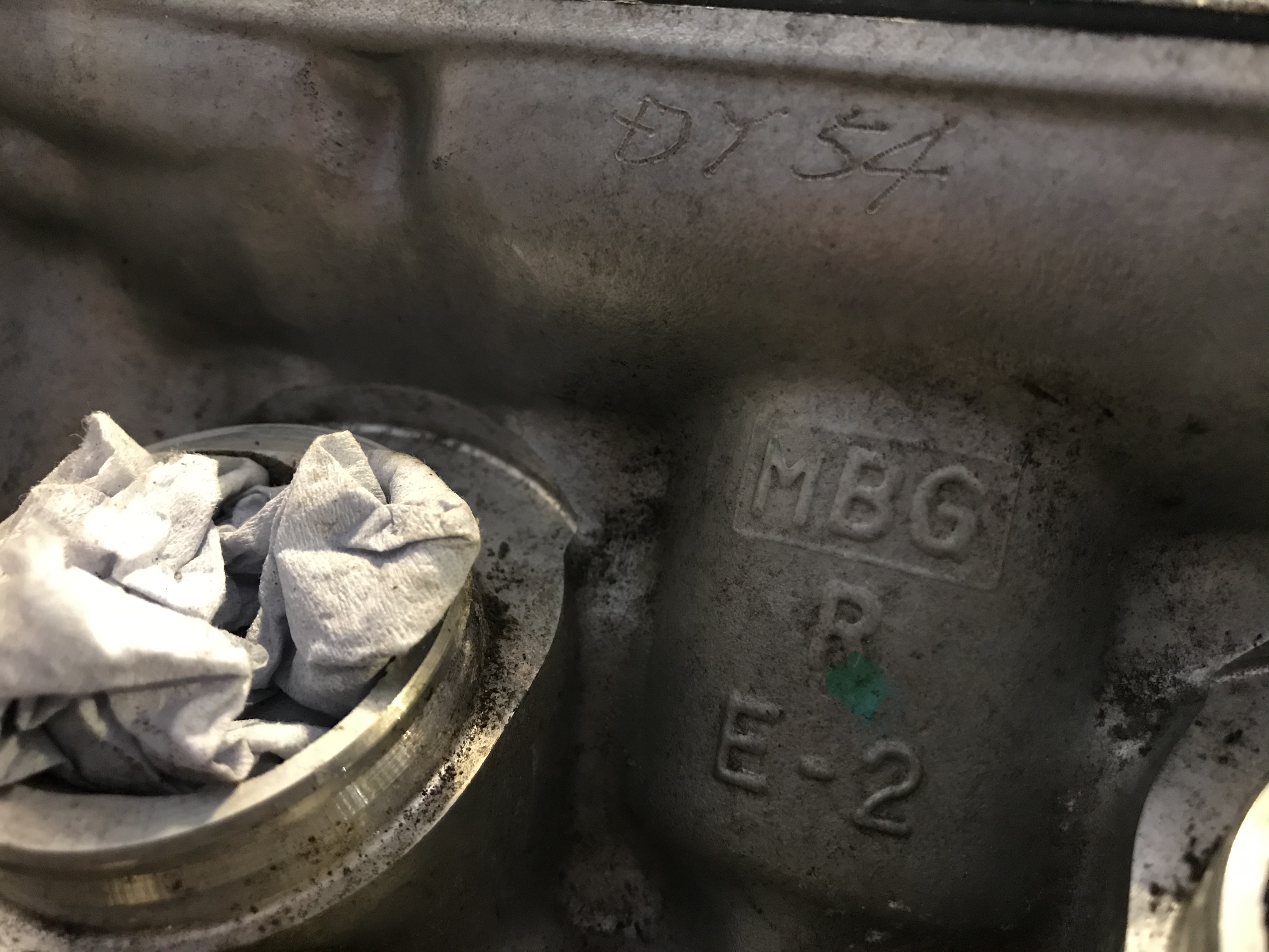
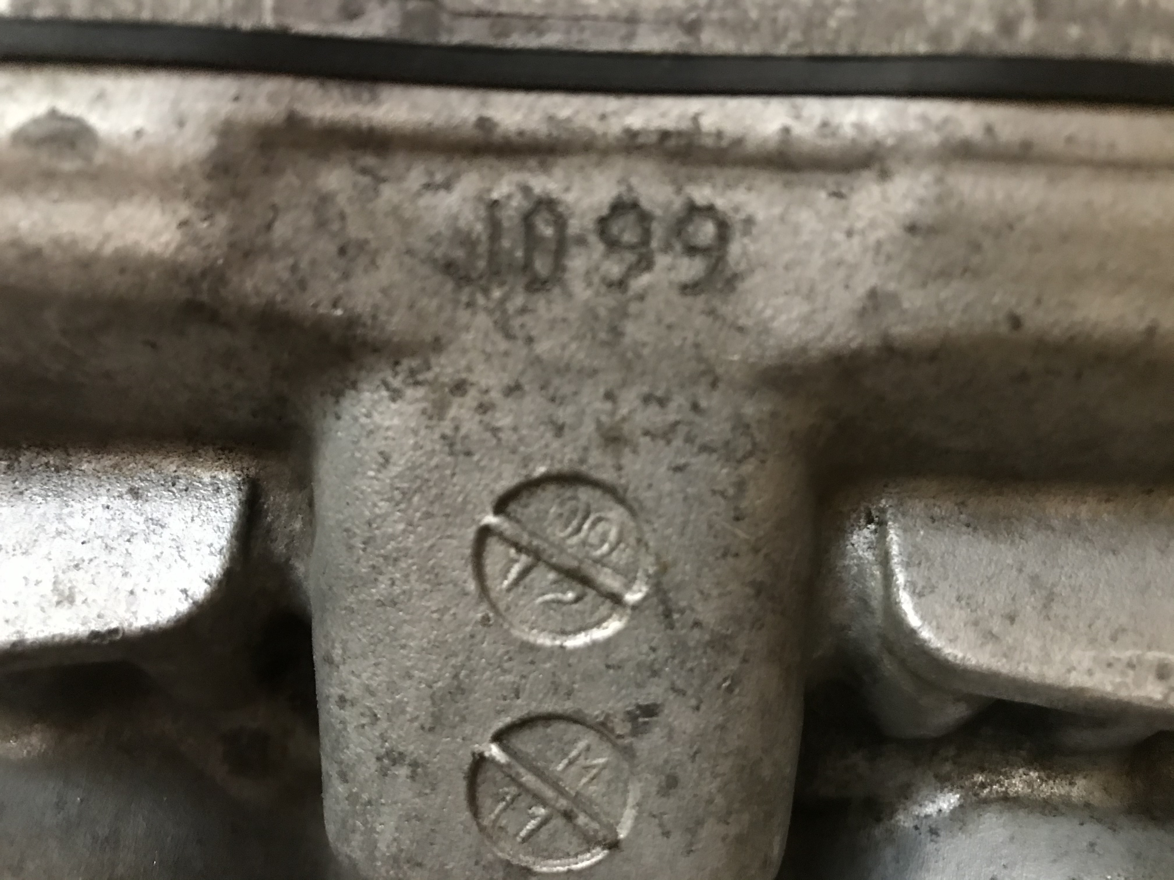
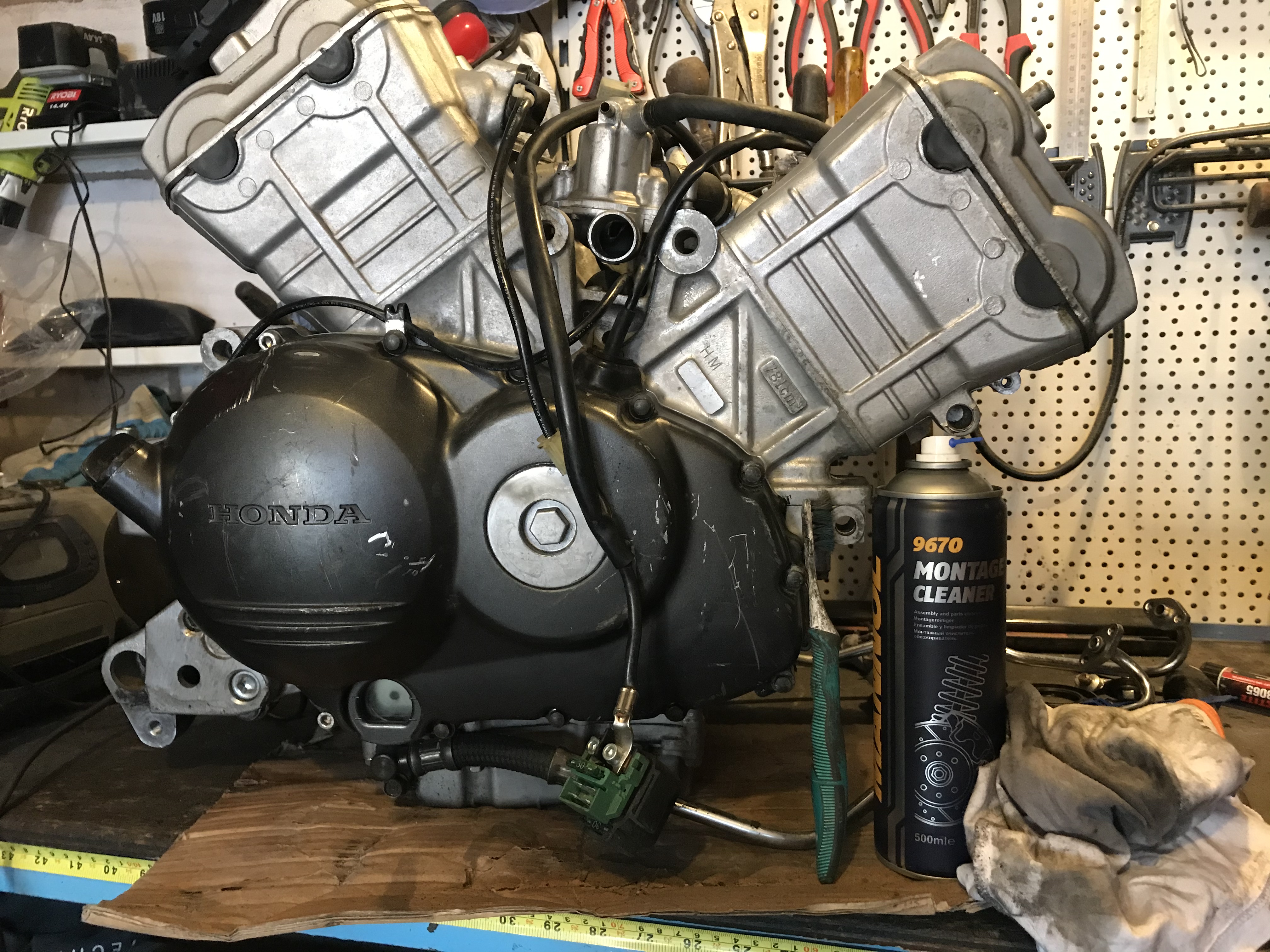
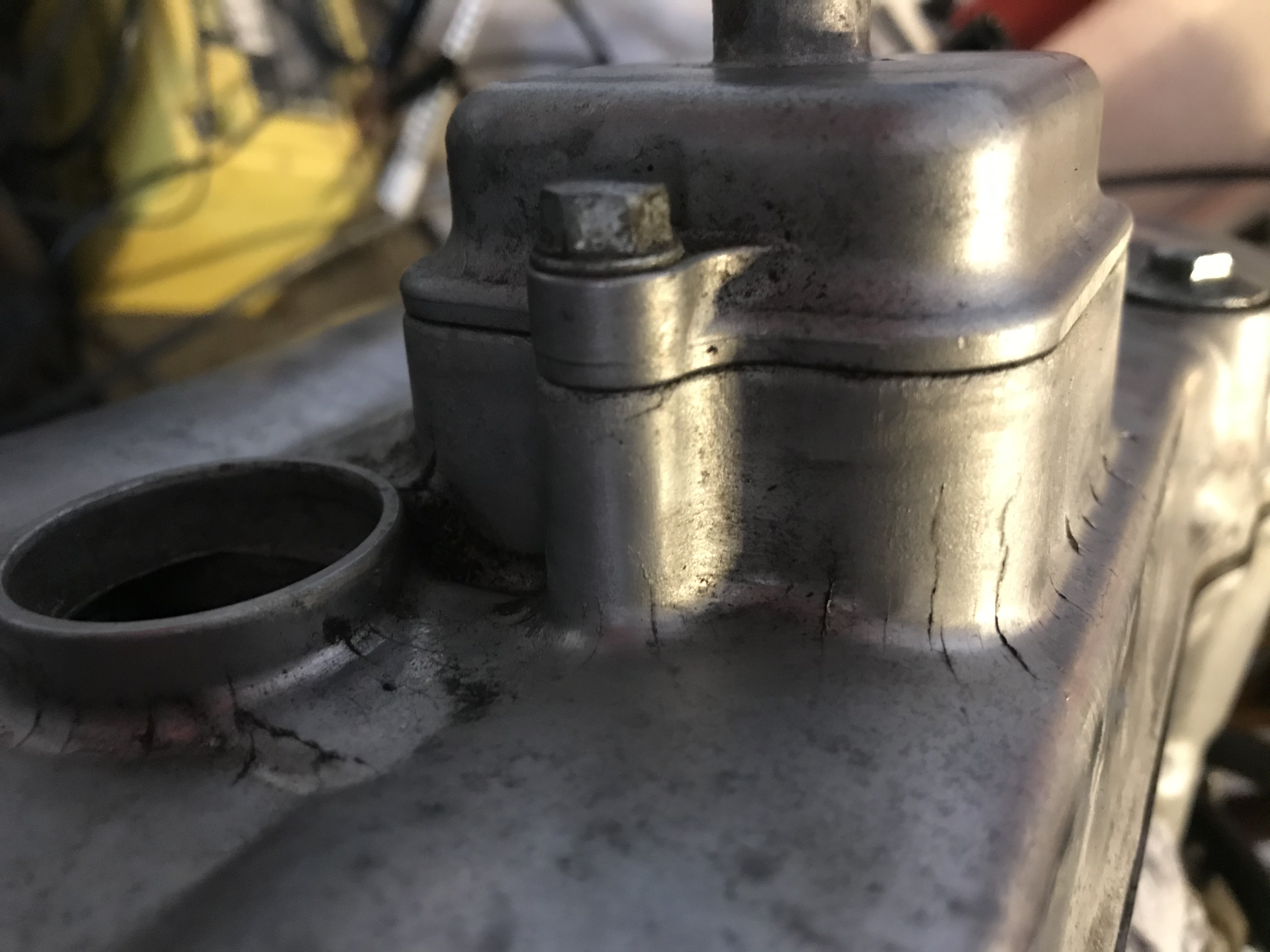
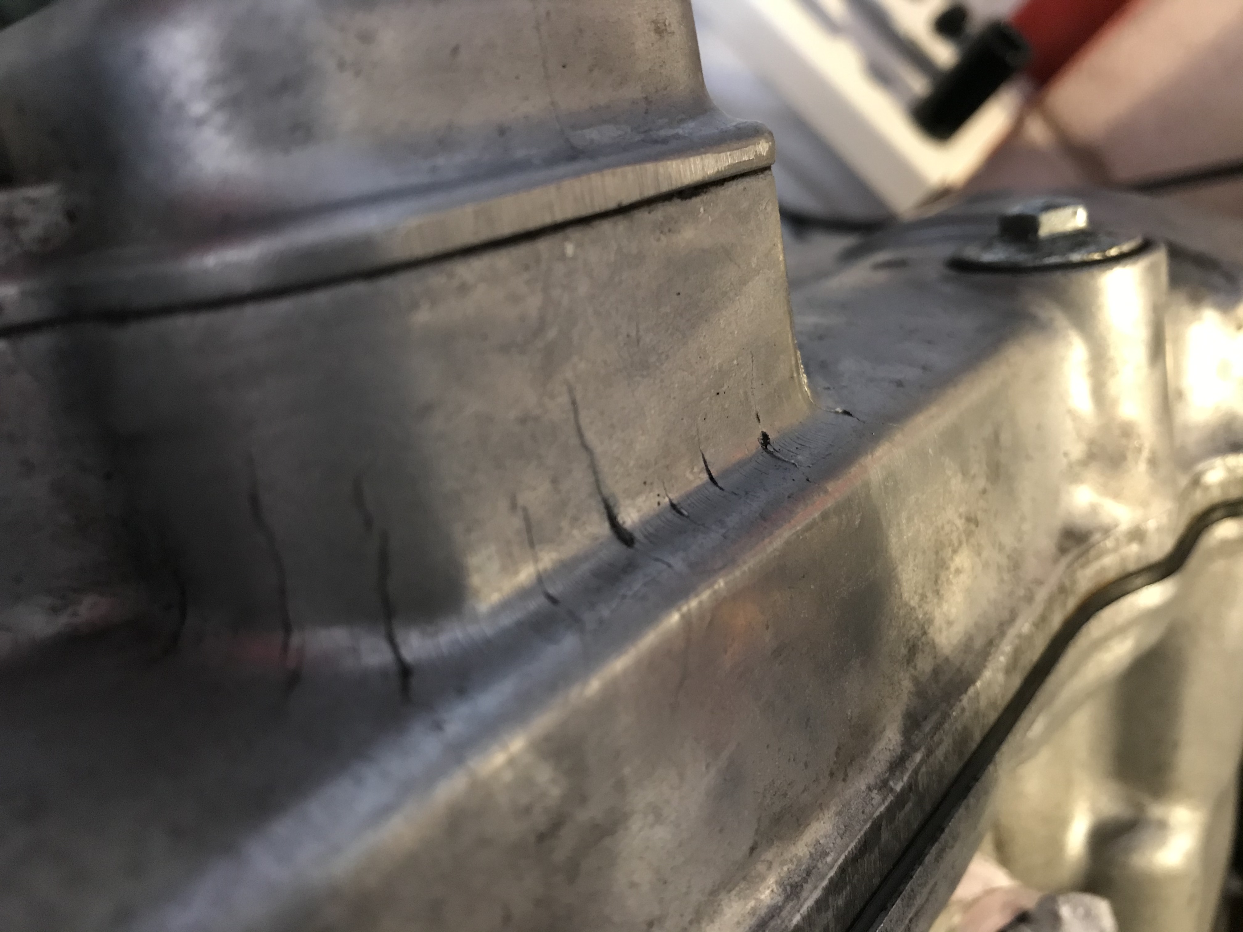
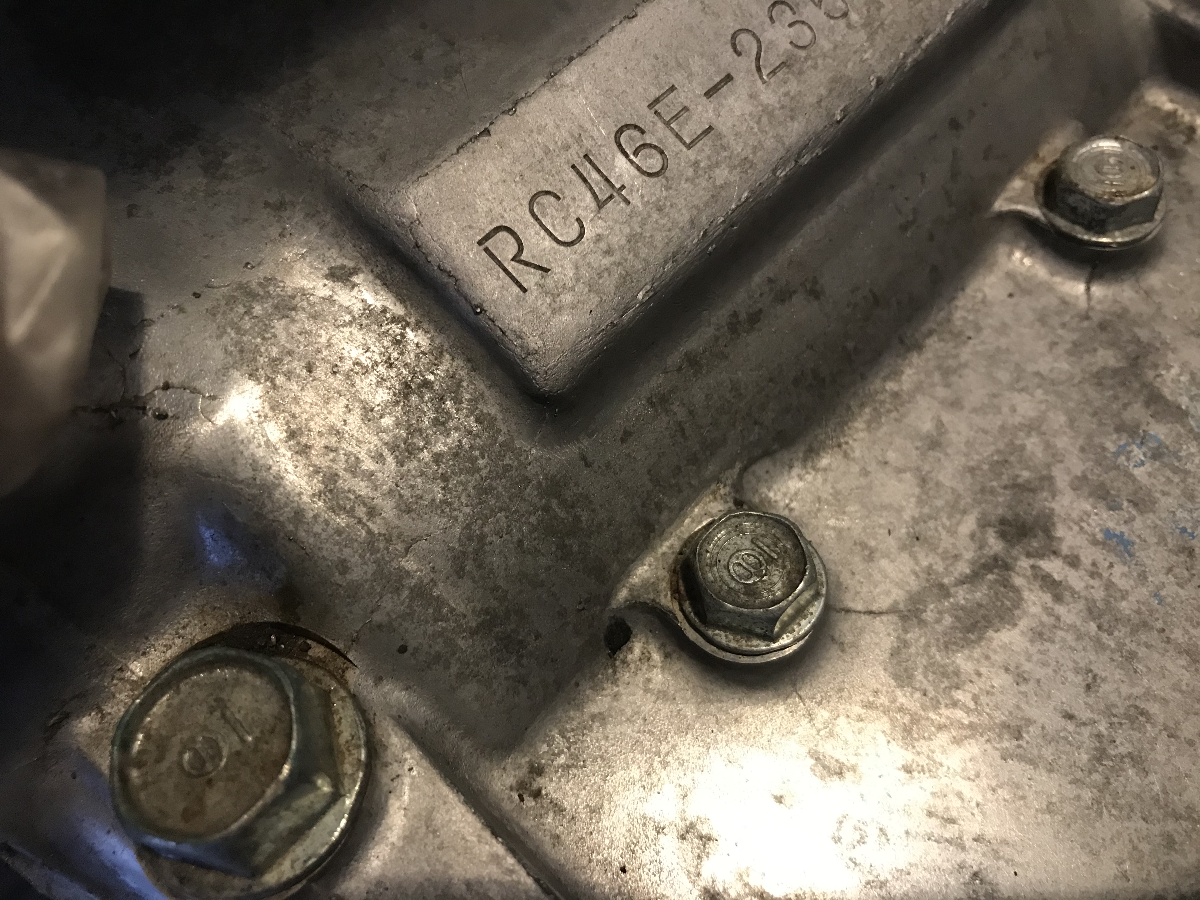
Hello All, Got me a lowish mileage 5th gen motor (10,000 miles) on the bench and just starting to get at her. I wanted to clean the crud off before opening her up to keep dirt out of the bits I upgrade. Bit of brake cleaner and a toothbrush never hurt anyone... Whilst scrubbing I noticed some scribe marks appear from under the the grime. Serves me right for removing her protective film! The cylinder heads have codes scribed on either side by hand, at the top just under the cover gasket. Looked at the other 2 engines in the shed and they’re the same - never noticed this before! Here are a few pics: Looks like DZ35 Looks like DY54 Looks like 1099. Also two interesting round stamps with codes on. Any idea what these are from? Are they production line control numbers or do they relate to some machining tolerance or set of camshafts, for example? Got me curious! Also, I noticed some cracks in the casting surfaces. Really crummy casting in places. At first I thought they might be stress fractures but these appear in unstressed places too. Plus engine is low mileage. Here are some pics: They’re quite pronounced on the PAIR section and even the spark plug holes. Odd, as these aren’t stress areas. I’m going to swap a different set of covers on but it did surprise me. Closeup of the PAIR tower. Some small ones near the swingarm mount section of the lower engine cases (look at the two little bolts under engine number). In fact there are little ones everywhere. Really poor casting or poor alloying?
-
Hello All, I’ve been dreaming up this build for a few years and despite that still don’t have a clear picture of where it’s going to end up. With family and work commitments I get very little wrenching time (couple hours per moth if I’m lucky - seriously) so don’t expect regular updates. Anyway, the idea is to build an ultimate 5th gen that’s lighter, faster, nimbler and cool (the latter is subjective, of course). Inspiration comes from endurance racers of the ‘70s and ‘80s although the final look is still in the air. The central theme is the bike has to work first and look good second. But still has to look good...um...you know what I mean. Endurance racers have that wonderful utilitarian look. Every part of them has to function properly and there’s nothing on it that doesn’t need to be there. Hopefully I’ll finish this someday and I’ll post bits and pieces here as she progresses. Some parts of this build feature in other threads so I’ll try to summarise here to keep everything in one place. Finally, I’d like to thank the fantastic membership here for their help with modifications and upgrades etc. This build is an homage to all of you and would not have been possible without your ingenuity. Best, Stray
-
New 5th/6th/8th gen performance header now in production in USA
Stray replied to sfdownhill's topic in Exhaust Systems
This thread could do with an index! -
New 5th/6th/8th gen performance header now in production in USA
Stray replied to sfdownhill's topic in Exhaust Systems
Thanks for chatting earlier, sfdownhill. Please put me down for a 8th gen system on the next run. Could even be persuaded by a 5th/6th gen system if needs be although would much prefer 8th. Best, Stray -
So I had a spare 5th gen sprocket cover in the shed and fancied tickling it with the angle grinder. Just for fun... Was going to remove just a bit of material but the grinder got away from me a few times and I ended up taking away more-and-more. There’s not much of it left. In the world of ball gowns this one’s a g-string! Took some material off the back end too. Was going to cut out the marked triangles but decided the chain oil spatter wasn’t worth it. It’s really light compared to the original sprocket cover. Must be worth 15bhp at least although it won’t turn anyone into Valentino Rossi on its own. Not sure how it will play in real life (might be a messy disaster) but there’s enough protection against the sprocket chewing up your shoelaces etc. If you’re going to try this I’d suggest ensuring the grinding is smooth without any sharp bits for cracks to form through vibration. Smooth for the win. And you may want to keep the belly section too. Mine “fell off” when the angle grinder decided to go it’s own way in a moment of inattention...
- 1 reply
-
- 1
-

-
There’s a great thread on here about fitting the Ducati hub and wheel to a VFR. Well worth reading. Swap looks fantastic when complete and saves a bunch of weight!
-
Nice work Hondatech and one hell of a first post!
-
Ranger, were you the first to do the swap? Awesome mod!