kaldek
-
Posts
1,317 -
Joined
-
Last visited
-
Days Won
11
Content Type
Forums
Profiles
Gallery
Blogs
Downloads
Events
Everything posted by kaldek
-
That is highly, highly unlikely. It's not a Ducati Panegale S, it's a ten year old VFR! So, someone copying my key based on my video and then tracking me down to steal my bike (which they will know has been in pieces and had lots of problems - based on my other videos)? Nah, there are easier targets on every street corner in Melbourne. Just because something is possible doesn't mean it's going to happen. Risk management is my day job, so I do lots of things people think are crazy because either A) the possible outcome is negligible or B) the likelihood is extremely low.
-
Wow, totally the opposite to how I ride, which is slow in fast out. I've always felt more comfortable doing that. Doesn't mean I'm right or fast though!
-
OK, now I'm *really* confused.
-
You'd need to test and compare current flow of both coil types somehow. Isn't this the one case where you can just measure the resistance across the terminals of the coil, and the result is indeed the impedance? I know all our talk about resistors in series wasn't right now, but isn't this measurement an exception? No, there is more to it. Something about electromagnetic something or other. I wish Bernie would get back online to help out with this. That might mean that the CBR stick coils - even though the measured resistance is wrong - could be just fine for our purposes...
-
You'd need to test and compare current flow of both coil types somehow. Isn't this the one case where you can just measure the resistance across the terminals of the coil, and the result is indeed the impedance? I know all our talk about resistors in series wasn't right now, but isn't this measurement an exception?
-
OK so you're saying that using resistors won't stop the coil from pulling too much current. I get it!
-
Resistance in series can absolutely work. There's lots of info and circuit diagrams showing how to do this, and it's the reason why running two 1.6 ohm coils in series results in 3.2 ohms of resistance. Same thing.
-
It should, considering that the purpose of the resistor here is merely to ensure that the coil does not get overcharged and that the coil does not demand so much current that the transistors in the ECU burn out. What I'm unsure of is whether the flyback voltage (10 microsend 400 volt pulse) could damage the resistor. It would be extremely low current though, so likely not. I suppose the right resistor would be a combination of ohms and the right wattage. And that's where my knowledge gets very hazy. Right now there are electrical engineers sharing this URL and laughing their asses off, I'm sure.
-
I can't remember now if I'd clarified this (as it was last year), but it's possible that just banging on a resistor in series with the +12v feed to each coil to bump it up to 3.2 ohms could work fine. I found some articles where people are already doing this on cars when the coil primary winding resistance was too low. So if the coils are 1.6 ohm but need to be 3.2 ohm, a 1.6 ohm resistor in series with the coil could be the way to go? Ultimately we need RangerScoot to get around to backprobing his coils and measuring the current with a digital oscilloscope and ammeter. If it tops out around 7 amps on his new coils - all is good. I have all the tools needed right here....in Australia.
-
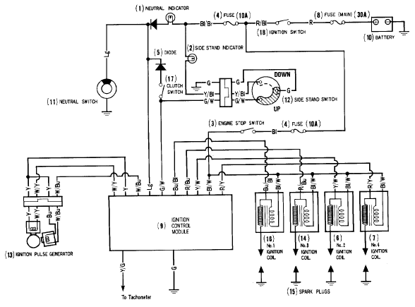
That diagram tells me that the '86 VFR750 is also TCI, as it's shared +12 volt power for all four coils.
-
Well it tells you that the bike is most likely TCI and that by merely looking at your wiring diagram you can confirm it. That means that the use of four Coil-On-Plug items of the same resistance as the existing coils will work fine, and a coil of any resistance should work fine if the EFI uses closed loop dwell control (which we haven't confirmed).
-
Lookee what I found - a 4th-gen ignition diagram. So it's definitely TCI, as all the coils share the same 12 volt feed from the engine stop switch. Same wire colour as on the 6th-gen too - Black/White. This wire colour is used as the common 12 volt feed for anything which needs a 12 volt source all the time the ignition switch is on and the Engine Stop switch is on.

-
I actually didn't know the difference between CDI and TCI and had been viewing everything as TCI. Checking into it though, since all the coils I've seen are 1.6 or 3.2 ohms I don't think they're CDI - those apparently have very low resistance (0.3 ohms or so). It's impossible to measure the resistance of the 6th-gen coils because they have the transistors inside the coil itself. I would guess that the 6th-gen is also TCI, as the coils are permanently fed 12 volts on one wire, have a dedicated ground wire and the third wire is the switch. This single wire should reasonably only be able to control a transistor that switched the 12 volt feed into the coil on (charge the coil), then off (collapse the field). So it's most likely TCI. Another way of checking if a bike uses TCI or CDI is to look at the way the coils (2-wire coils anyway!) are powered. If they share a common +12 volt feed and have individual ground wires going back to the control box, then they're TCI. However if they share a common ground but have individual positive wires going to the control box, then they're CDI.
-
Yep that's the way it's done. It only ever works if one of the new coils is half the resistance/ohms of the oil dual coil pack. So even though some of your other bikes will be dual-coil they may not be 3.2 ohms. If the original dual coil packs are much lower than 3.2 ohms, you will overcharge the new coils (too long a dwell time) and blow the coils/wear the plugs out fast, or undercharge the coils (too short a dwell time) and get poor spark. Unless your CDI has closed loop dwell control of course, in which case pretty much anything should work.
-
That's easy - run them in series as wasted spark. It's already a dual-coil (rather than quad-coil) setup isn't it? If it's wasted spark 3.4 ohms each coil with dual coils you just wire two 1.6 ohm stick coils in series. (1 & 4 and 3 & 2).
-
He's probably disconnected another vacuum hose accidentally, probably the fuel pressure regulator hose. It connects to the two right-hand side cylinders so he's probably tried to sync the bike to cylinder #4 when that was already out of whack. There's also the flapper valve vacuum hose on the front left cylinder, and if it's a US-model bike with the evap cannister it has an extra vacuum line again for ALL the cylinders which can also be accidentally disconnected.
-

Anyone attempt to connect radiators in series?
kaldek replied to tinkerinWstuff's topic in Modifications
So how about a link then? As I said in my OP, I've read plenty on the fan mod but have never seen a discussion on routing the hoses differently. Sorry I meant the "spin your fan backwards" thread. http://www.vfrdiscus...6th-generation/ http://www.vfrdiscus...e__hl__radiator Basically lots of folks saying the stock design is flawed, yada yada. But, has anyone heard of a VFR overheating and warping the heads? I've been on the forum here for ten years and I don't recall a single one. My opinion is that the stock design works best when the bike is stationary or moving slowly. If you flip the fan, it will work WORSE when the bike is stationary because it's pulling already-hot air from the engine rather than cooler air from the outside. Someone at Honda ran the numbers on this and they were obviously right, because no VFRs have yet overheated and blown head gaskets or warped heads. In this case, stock works. As for the running the radiators in series, you may find that the pump hasn't got the balls to move the coolant around and may just cavitate, creating a lot of froth and not much movement of coolant. -
Anyone attempt to connect radiators in series?
kaldek replied to tinkerinWstuff's topic in Modifications
Honestly, this argument has been done to death in various forms. People spinning their fans backwards because "it's better than the Honda design" went on, and on, and on. Have you seen the cooling fan on a CBR1000RR? It's about one-eighth the size of the radiator, in the upper right corner. That's it - and it works. Our bikes have two radiators, and the fan is basically the same size as the entire left-side unit. It's fine, it works, and I've seen it keep my bike at 231F when the ambient air temperature was 116F! This was in traffic, too. -
Rotors don't wear out, so no need to replace. Outer diameter of original 2002 model stator is 107mm. Outer diameter of upgraded stator is 115mm. I have one of each in my garage just lyin' around.
-
You cannot just disconnect the wires because the PAIR system is enabled by default when there is NO power applied. Only when power is applied does PAIR shut off (it closes a valve). PAIR is always active except when the engine goes into closed loop mode (i.e. the O2 sensors trim the fuel), which is not very often. Sticking a marble in the hose that comes from the airbox and goes to the PAIR valve solenoid will do the same thing as the PAIR block off plates. You need to raise the idle speed as well, and potentially adjust the fast idle wax unit as this controls cold engine idle speed. Both are affected when PAIR gets blocked off.
-
Yeah same procedure for all HISS bikes.
-
 Balls of STEEEEEEEEEEL!
 -
Installing an American ECU on a European or Aussie bike
kaldek replied to kaldek's topic in Modifications
Yeah, but testing continues. I'm waiting on the diagnostic tool from HealTech so I can see what the ECU thinks is going on. I'm also going to do valve clearance checks and some other mechanical checks to make sure the problem is not being caused by some form of issue affecting engine vacuum. -
If you lose all the keys to an Australian or European bike, you are faced with an expensive prospect to get the bike running again, as the ECU is coded to transponders in the keys (via H.I.S.S). It is possible these days to have your old ECU reprogrammed via some folks on eBay, but what if you find an American ECU somewhere much cheaper? Unfortunately Honda expected that nefarious folks might try this when stealing motorcycles, so they modified the wiring harness. American ECUs won't work on European or Aussie wiring harnesses - or will they? I mapped all the pins on both my Aussie wiring harness and American wiring harness that I happen to have lying around. It turns out that the only difference between the two harnesses is that American systems use two power feeds into the ECU rather than one. Both feeds are the black/white wire, which is the +12V signal from the engine stop relay. Anyone familiar with the 6th-gen wiring will know this is the circuit used to power pretty much the entire FI system (PAIR solenoid, EVAP solenoid, airbox flapper solenoid, injectors, coils, fuel pump relay). So in order to get your USA ECU to work on a Euro bike, you need to remove a pin and wire from somewhere else on your ECU connector plug, and move it to the pin where the additional power feed is needed. This pin is on the grey connector, pin #16. Once you have inserted your relocated pin into this hole it will clip into place, and you can then splice the wire into the black/white wire from the engine stop relay. The wire you relocate can be any of the following pins from the grey connector, as they are not used on the USA model ECU: Pin #1 - Blue wire Pin #12 - White/Red wire Pin #14 - Pink Wire Pin #32 - Orange/Blue wire Note that this process is specific to 2006 and newer models. Older units may "just work" or may also require relocation of a pin. WARNING: You cannot put an ECU from a 2002-2005 bike on a 2006+ model bike without also replacing the wiring harness, as the ECU hardware and connectors are totally different.
-
Wow that must be one tight track!