GreginDenver
-
Posts
307 -
Joined
-
Last visited
-
Days Won
7
Content Type
Forums
Profiles
Gallery
Blogs
Downloads
Events
Everything posted by GreginDenver
-
New 5th/6th/8th gen performance header now in production in USA
GreginDenver replied to sfdownhill's topic in Exhaust Systems
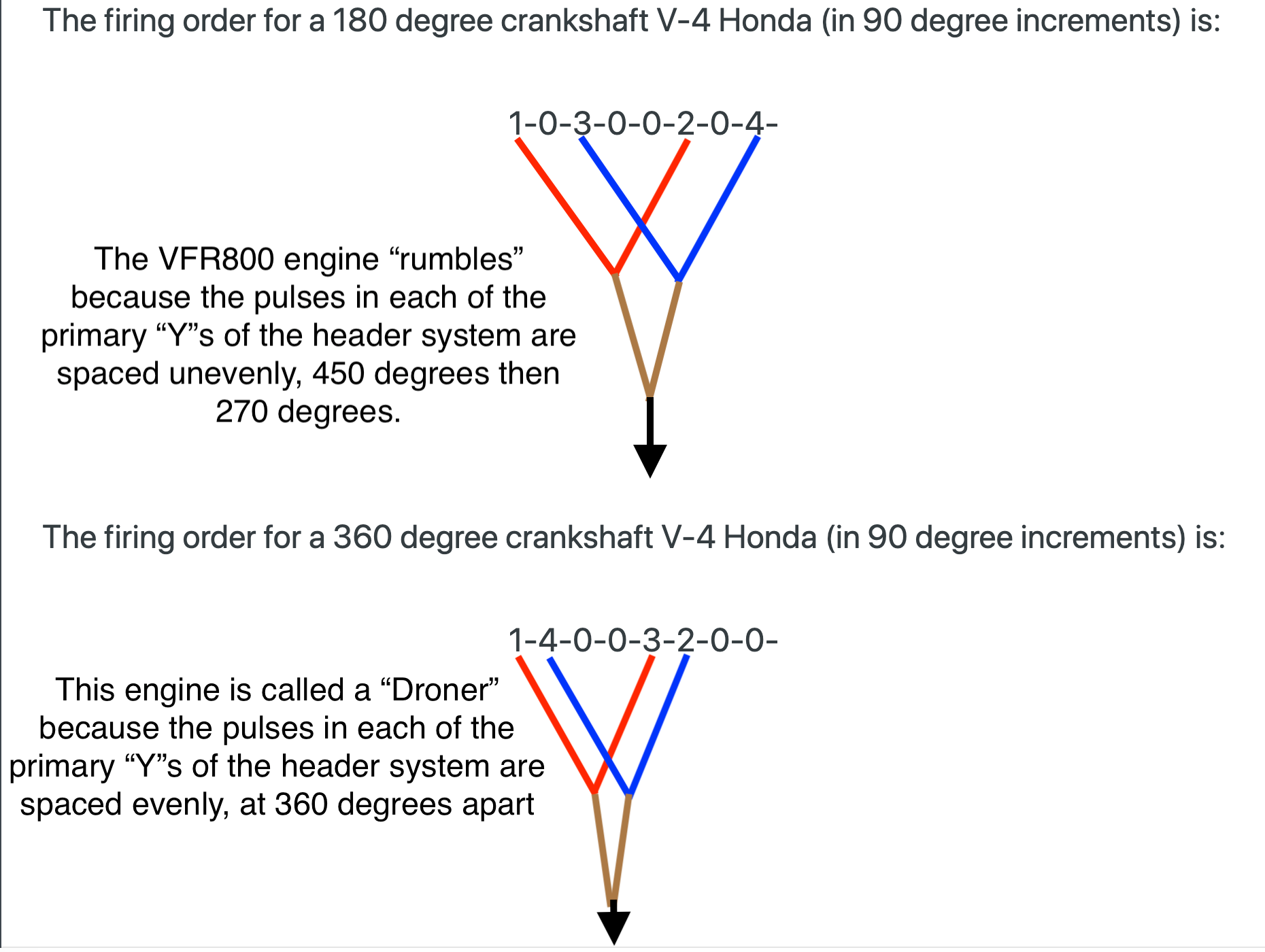
You can also see from the drawing that in both cases (both the 180 degree crankshaft engine and the 360 degree crankshaft engine) the primary headers are on cylinders that provide the widest possible spacing of exhaust pulses into both the primary "Y"s and into the final merge (the "collector"). This is how you arrange things for good gas flow through an exhaust system.
-
New 5th/6th/8th gen performance header now in production in USA
GreginDenver replied to sfdownhill's topic in Exhaust Systems
Yes this is still happening. It appears that we (those of us already in with deposits on the current group-purchase) have stalled out below the number of header systems required for an order to go forward to production. So if you come in and add yourself to those who've placed deposits we'll be closer to "go!". -
New 5th/6th/8th gen performance header now in production in USA
GreginDenver replied to sfdownhill's topic in Exhaust Systems
You really don't know what you're talking about. This will probably piss you off, but it's the truth. -
Actually there's an all-in-one fuel pump solution that's available from Honda. It's a self-contained external (as in: not an in-tank pump) that Honda uses on its fuel injected TRX 4-wheel ATVs and on their big V-twin cruiser bikes. It's an aluminum housing that includes an electric fuel pump, a 43psi fuel regulator and a "sock" type fuel filter. There are two versions of this fuel pump, one is for engines up to about 550cc and the other is for engines up to 1300cc (the big VTX 1300 cruiser bike). The two versions are externally identical, just the pump volume is different. I used the lower volume version on both of my EFI project bikes, one is 250cc bike while the other is a 400cc bike.
-
And... and... and... and... When you add the MicroSquirt ECU you can also implement full ignition control, which allows you to custom tune the timing and dwell of the ignition coils. The OEM Honda ignition settings are really on the conservative side, there's more ignition advance that can be tuned into the bike without hurting anything. I installed "stick coil" (coil-on-plug) ignition on my EFI project bikes. The DENSO corp stick coils that Honda used on the CBR600RR were perfect for my projects.
-
Exactly what would those problems be? I can tell you that both of my carb-to-EFI motorcycles run better than they did on carbs. The best thing about my EFI converted bikes is that I can let them sit for months and they start right up (I've let them sit through a full winter with no more effort than hooking up a battery tender). I'm not saying that carbs aren't a fine solution for fuel delivery, they are fine. But some people just want to tinker and experiment and improve things, they like to have a project to work on. That was me. I didn't enjoy cleaning and rebuilding and tuning carbs, but I really like the challenge of configuring and installing and running a fuel injection system (tuning air/fuel ratios as I ride the bike around with a laptop computer hooked up to the MicroSquirt ECU). If you've got the necessary skills/knowledge/time/tools a project like this is a very fun and satisfying thing.
-
I've done two motorcycle carb to EFI conversions, a Kawasaki EX250 and a Suzuki GSF400. On both bikes I used the MicroSquirt V3 ECU. If I was doing an EFI conversion on a bike like the VFR750 with its unusual "V" configuration I would convert the original carb set into throttle bodies (which is what I did on my Suzuki GSF400 conversion project). The reason for doing this (instead of trying to engineer up a custom set of 4 throttle bodies into a functional "V" configuration) is that getting things like the throttle actuation linkage rigged to work properly and reliably (meaning: getting the linkage to simultaneously open all four of the "V" configured throttle bodies the exact same amount when you twist the throttle) is really, really difficult.
-
Yes, the reality of the "pulsing rotor" situation on a car or motorcycle can be a warped rotor, but the more common cause is an actual re-tempering (by heat) of a small (brake pad sized) area of the steel alloy of the brake disk. When a brake disk is heated up to very near its maximum operating temperature, due to something like a situation where there was a long period of brake use on a long downhill run (this is common with inexperienced drivers who don't know how to "gear down" the transmission rather than constantly use the brakes), and at the end of this period of extreme heating if the driver/rider is faced with a reason to come to a complete stop and sit for a while (like a traffic light or a stop sign) if the driver/rider holds the brake lever/pedal down during that time the area of the brake disk that is located under/between the brake pads can undergo what is essentially a re-tempering of the area under/between the brake pads. This re-tempering of the small area of the brake disk held under/between will result in a slight change in the crystalline structure of the steel alloy in that area. Once the brake disc cools the change is permanent. Forever after this event this small portion of the brake disc's surface area that got re-tempered by this extreme heating event will have a slightly different coefficient of friction from the rest of the brake disc area. The permanent result of this change is that when you squeeze the brake lever (or press the brake pedal) the brake pads will experience less "bite" (a lower coefficient of drag) as they sweep over the small (brake pad size) re-tempered area of the brake disc.
-
New 5th/6th/8th gen performance header now in production in USA
GreginDenver replied to sfdownhill's topic in Exhaust Systems
I didn't want to cut away material. I gave some consideration to going the Dremel route but decided to keep all of the original strength that the fairing chin insert had. I just wasn't in the right mood to start cutting on things (in the past I've done a lot of Dremel modifications to motorcycles, but so far I haven't done any to either of my 5th Gens, maybe that was a factor in today's choice). My opinion on the Dremel vs. heat-bending situation is that neither solution will leave the chin insert "speed holes" looking as good as they did in their OEM profile. So definitely go with your personal preference. Either way the fairing chin insert isn't something I notice when I look at a VFR, it's pretty much out of view from almost any angle. And if someone does notice the bent area it'll give me the perfect opportunity to bore the pants off them by telling all about my totally bitchin' stainless steel performance exhaust system. -
New 5th/6th/8th gen performance header now in production in USA
GreginDenver replied to sfdownhill's topic in Exhaust Systems
As others have already said, I like the "new header" enough that I'm willing to live with a little inconvenience. Here are pictures of my work to provide clearance for the header from the #4 cylinder. I imitated sfdownhill's solution to the problem, I used a heat gun to soften up the plastic so it could be re-formed with an outward bend that gives the #4 cylinder's header about the same amount of clearance as the #2 cylinder's header pipe. Installed on the bike you can see that I've managed to achieve the same amount of fairing-to-header pipe clearance on both the #4 and #2 headers. I happened to have some high temperature heat reflecting tape on hand so I added it to the work I did. I figured why not, regardless of whether the situation really needed this amount of protection Maybe I got a little carried away with the heat reflective taping... -
New 5th/6th/8th gen performance header now in production in USA
GreginDenver replied to sfdownhill's topic in Exhaust Systems
Yeah, sorry, you know how it goes, when you've decided on the solution you're going to use it puts the finish line in sight and you start looking forward to test-riding the bike. I definitely preferred the results I got with the 41mm copper gaskets over what happened when I tested the 42mm copper gaskets. This is still very much a situation that's "in play", it may turn out that another New Header purchase forum member will come up with the discovery of a completely different gasket solution that would be better than the 41mm copper gaskets from Delkevic. But at this point I firmly believe in the 41mm as the best solution I had available. I was very impressed by how neat and easy it was to install my New Header. I used a "spreader" type clamp to ease the header around the center stand crossbar (which is slightly smaller than the center stand leg), this worked great. My New Header matched up to the exhaust ports just as others have described, so I used a couple of Thule Rack cargo straps to put some pull force on where I needed it, like having an extra pair of hands. -
New 5th/6th/8th gen performance header now in production in USA
GreginDenver replied to sfdownhill's topic in Exhaust Systems
Not sure what you mean by "match." I can tell you that I noted a very slight difference in the diameter of the New Header mid-pipe exit. The New Header exit is just a tiny bit larger than the original 5th Gen exit. When I had my Vance&HinesS4 mounted on the original 5th Gen exhaust I was able to slip it onto the exit using the standard Honda OEM carbon+mesh gasket. When I installed the new header I discovered that due to the New Exhaust's ever-so-slightly-larger exit there was no way to use the Honda OEM carbon+mesh gasket, there just wasn't enough room (the carbon+mesh gasket is pretty delicate so you can't force it into a space that's too small without destroying it). So I ended up using a do-it-yourself custom sized wrap of high-temp aluminum tape (stuff that's good to about 700 degrees F). I don't know if I'll stick with this solution, I had the aluminum tape available at the moment and I wanted to take the bike out on a ride to hear what the New Exhaust + Vance&HinesS4 combo sounded like. Let me know how your install goes, and if you can think up something that's a better substitute for the Honda OEM carbon+mesh gasket. -
New 5th/6th/8th gen performance header now in production in USA
GreginDenver replied to sfdownhill's topic in Exhaust Systems
Depending on what you mean by "after" I might be able to show you something. So what do you mean? -
New 5th/6th/8th gen performance header now in production in USA
GreginDenver replied to sfdownhill's topic in Exhaust Systems
I just finished the final install of the header, it's midnight here in Denver but I went ahead and rolled the bike outdoors to run it. The install is a success, no leaks, sounds great. I let the bike idle up to about 170 degrees on the temp gauge then shut it down and pushed it back into its parking spot in my garage. In the end I decided to use the 41mm copper gaskets from Delkevic. They are just a little less than twice as fat as the 42mm copper gaskets that Delkevic sells. Because they are fatter I knew that during the installation "crush" they would probably end up spreading inward to about the same inner diameter as the original Honda OEM gaskets. I didn't like how much the OEM gasket protruded into the exhaust flow and wanted my install to be better than that, so I decided to experiment a little. I purchased 8 of the 41mm copper gaskets directly from Delkevic at their location in Littleton, CO. Got to meet and chat with Matt (at Delkevic), he was very friendly and helpful. I modified the 41mm gaskets by "pre-pinching" them inward, only by a little bit around the outside perimeter and then by as much as possible around the inner perimeter. I did this so that when the crush of the install occurred the gasket would have a smaller starting point from which to spread. The results were pretty good. I practiced installing a couple of my "pre-pinched" 41mm copper gaskets on the front cylinders and after the crush they ended up with an inner diameter that was noticeably wider than the original Honda gaskets (although they do protrude slightly above the inner edges of the exhaust ports). So I'm satisfied, the modified 41mm gaskets provide a very good, generous footing for the end of the header to bed into and their inner diameter is better (wider) than the OEM gaskets. Good enough for me. On to other maintenance items... -
New 5th/6th/8th gen performance header now in production in USA
GreginDenver replied to sfdownhill's topic in Exhaust Systems
I don't know if the cylinder castings of all of the 5th & 6th Gen VFRs are the same, but if you look closely at my pictures of the exhaust ports (above) on my 5th Gen you'll see why I was more worried about the front cylinders than the rear cylinders. The gasket seats for the rear ports have a retaining wall all the way around their circumference, but for some reason Honda decided that the front ports would have a long stretch of the circumference without a retaining wall. I was concerned about what would happen in this section. As you can see in the pictures, I got what I'd describe as some pretty weird looking gasket deformation on every cylinder: On both Cylinder #2 & Cylinder #4 the section that lacks a retaining wall allowed the slightly oversized gasket to bulge outward under the force of installation, on Cylinder #1 the partial crush resulted in the gasket catching the retaining sidewall and uncurling against it (don't know how far this effect would have gone with a full install crush), on Cylinder #3 the partial crush of the gasket with the seam facing outward shows a lot of stress bending and buckling. -
New 5th/6th/8th gen performance header now in production in USA
GreginDenver replied to sfdownhill's topic in Exhaust Systems
Now that I've seen the above-pictured results I've decided to change to the 41mm copper Delkevic-supplied gaskets. I live in Denver, 11 miles away from Delkevic and Matt (at Delkevic) has told me (via email) that I can order and pay for them at their online store and then drive over to pick them up in person at Delkevic in Littleton, CO. -
New 5th/6th/8th gen performance header now in production in USA
GreginDenver replied to sfdownhill's topic in Exhaust Systems
I've just finished removing the exhaust system from yesterday's trial-fitting. Here are pictures of the installation crush results with the 42mm copper gaskets from Delkevic. (NOTE: I didn't fully torque-to-spec on the rear cylinders so I believe the front cylinders (#2 and #4) are the best representation of the install results with the 42mm copper gaskets. And, obviously, I wasn't watching closely when I was pressing the gaskets into the ports, otherwise I would have installed all of them with the seam facing inward which is what I intend to do for the final assembly) Here is Cylinder #2: Here is Cylinder #4: Here is Cylinder #3: Here is Cylinder #1: -
New 5th/6th/8th gen performance header now in production in USA
GreginDenver replied to sfdownhill's topic in Exhaust Systems
As I mentioned I'm concerned about the part of the circumference where the 42mm copper gasket was bowing a bit out-of-round as I was using my fingers to press-fit the gasket into the cylinder head ports. No, not overthinking here, I'm going to come to a decision on this purely from the evidence provided by visual confirmation tomorrow when I remove the exhaust system. I'll take some pictures of the gaskets in the ports tomorrow after I've removed the exhaust system. We'll see if the bowing-out resulted in and area where there's only a thin bit of the gasket crushed under the header. And we'll see how close to the inner edge of the cylinder head exhaust port the 42mm gasket comes after being crushed in the install process. -
New 5th/6th/8th gen performance header now in production in USA
GreginDenver replied to sfdownhill's topic in Exhaust Systems
Okay, I'm still in the garage right now, just finished a trial install of the headers, went ahead and used the 42mm copper gaskets because I figured that when I remove the headers tomorrow I'll be able to assess how well the gaskets seated themselves when they were pressed into the cylinder head seats by the headers. My trial install went really well, I used several cargo straps as strong and consistent helpers to pull the headers in the directions I needed and then hold them steady while I guided the headers into the cylinder head seats. This strategy worked like a charm, with cylinder number 1 and number 4 requiring the most persuasion. I'm going to leave the header installed overnight then remove it to have a good look at the copper gaskets. I live here in Denver, not far from Delkevic's address, might call them and drive over to get more gaskets. I'm considering experimenting with 41mm gaskets, I don't know if I can accept the fact that the 42mm gaskets were bending "out of round" on part of their circumference when I was pressing them into the cylinder head ports. When I remove the header tomorrow I'll know for sure. -
New 5th/6th/8th gen performance header now in production in USA
GreginDenver replied to sfdownhill's topic in Exhaust Systems
What size are the copper gaskets for the headers? I remember reading that it's recommended that we purchase a particular size of the copper gaskets from Delkevic. I skimmed back through this forum thread but couldn't find the exact size in millimeters or a serial number or product SKU. I ask this question because I thought the correct size was 42mm in copper. I ordered a set of these gaskets (42mm size in copper) from Delkevic. Today I was trying to install the header and discovered that on my '99 5th Gen VFR these 42mm copper gaskets do not fit. When I try to press-fit these 42mm gaskets into the header ports the gaskets end up going "out of round" because the diameter of the gasket is just too large. -
New 5th/6th/8th gen performance header now in production in USA
GreginDenver replied to sfdownhill's topic in Exhaust Systems
(I feel like the clueless kid at the back of class) Can I ask why? Exactly why are we talking about exhaust coatings here in this forum thread? I have to know, is there a specific reason or concern or flaw (in these new stainless steel headers) that has caused the discussion to be re-directed onto the topic of header coatings? -
New 5th/6th/8th gen performance header now in production in USA
GreginDenver replied to sfdownhill's topic in Exhaust Systems
I'm probably wasting my time saying this but here we go anyway: I have about a decade of experience with motorcycle fuel injection systems that use Bosch wide band O2 sensors mounted at a level angle. On both of my do-it-yourself fuel injection motorcycles it turned out that I needed/wanted to mount the O2 sensor at a level angle. So 10 years ago when I was building up my first FI motorcycle I was asking/worrying about this exact issue. I ended up having the opportunity to have a back-and-forth email dialog with a couple of Bosch engineers from the division that produces these sensors. You wouldn't believe how unconcerned these two guys were about the effect of mounting one of their O2 sensors at a level angle. They basically said that the "mounting recommendation" drawing was produced because it had to be done, a requirement demanded by the management. Their opinion was that as long as you don't mount the sensor at a downward angle you won't have any problems. My experience with my FI project motorcycles bears this out, no problems at all. Every so often I remove the sensor from the bung to do a "free air" recalibration of the O2 system and the sensor always looks good, just light carbon coating that you would expect. -
New 5th/6th/8th gen performance header now in production in USA
GreginDenver replied to sfdownhill's topic in Exhaust Systems
pictures of the parrot helping with the packing process? -
Once again, the 5th Gen VFR air box has 2 intake paths for a very good reason: from idle to about 7,000 RPM the rubber snorkel provides a level of airflow which causes the air box achieve a resonate frequency in that RPM range. When the air box hits a resonate frequency it boosts intake efficiency, which boosts torque in that rev range. After about 7,000 RPM the 5th Gen air box opens up the flapper. This changes the resonate frequency equation, moving the air box resonance point to the upper end of the engine's rev-range. Also, the 5th Gen VFR's rubber snorkel intake is long, which is exactly what you want for the lower end of an engine's RPM range. The Flapper side of the air box intake is short, which is exactly what you want for the upper end of an engine's RPM range. As others have pointed out, the 5th Gen air box acted in a similar way to the VTEC system in the later generations of the VFR (this also explains why the dual-path air box was dropped in the VTEC versions).