
Grum
-
Posts
3,801 -
Joined
-
Last visited
-
Days Won
117
Content Type
Forums
Profiles
Gallery
Blogs
Downloads
Events
Posts posted by Grum
-
-
12 hours ago, SABen said:
Previous owner left everything to dealers, I showed him some faults he was not aware of when viewing the bike so not much there
Will remove the fairings this weekend and start measuring and tracing and checking for cables that aren't part of the loom.
Will make some notes as I go as this will be my first time chasing a electrical issue and that wiring map is already making my eyes hurt
Some good voltage checks especially around the ESR, voltage on fuse test points Ignition On and Off, visual inspections for strange wiring, continuity check of Ignition Switch function. Are all good starting points.
Download the Service Manual form the forum if you don't have it.
May the Force be With You....There's plenty of info to get the ball rolling, very interested in what you may discover, post photos.
Strangest VFR fault I've ever heard of!

-
Can you unplug the R/R run the engine, is there any change to the Ignition Switch operation? Grasping at straws a little now.
- Suggest accessing the Ignition Switch 4P plug and do some continuity checks confirming good Switch operation. Refer bottom left corner of wiring diagram for Switch Connection Table.
I'm struggling to relate your symptoms to the wiring diagram, also struggling with what or how a wiring modification could induce such strange issues with two separate switch functions.
-
19 minutes ago, SABen said:
But now I can do you one more - When the engine is not running, the ignition switches off normally, and it doesn't matter if the kill switch is on or not
Bloody hell!
Now I'm really confused, this is crazy. Check for Non OEM wiring.
Are you able to get any feedback from the previous owner as to wiring changes or anything done electrically to the bike?
-
1 hour ago, SABen said:
- Keys off and out - Lights and Instrument panel stays on while engine keeps running
RIGHT - This explains part of the Fault. The Ignition Switch is faulty or you have a Red wire to Red/Black wire short, powering Fuses C,D,E, and F. Refer Ignition Switch wiring on previous diagram.
But how on earth does activating the Kill Switch then turn Off power to these circuits??
Strange wiring modifications maybe.
Important now to check all voltages at the ESR with Ignition ON/OFF and Kill switch 12v Power to ESR Black wire.
Note - Engine can Only continue to Run if 12v Power on the all important EFI power wire being the Black/White from the ESR is there when it shouldn't be. eg When Kill Switch activated or Ignition to OFF.
-
On 4/19/2024 at 4:44 AM, nismogt1 said:
My concern is that the current owner has been running a DAM muffler with a K&N air filter in it. Without a tune on the ECU to compensate
Never been an issue with all 4 VFR800's I've owned with after market exhausts fitted, 1200 shouldn't be any different.
O2 sensors means ECU runs in closed loop, so air to fuel ratio is continuously optimized.
Think you're worrying about nothing. I'd probably go back to the OEM type airfilter if it was mine!
Good Luck with the bike, take it for a good test ride.
Check it's maintenance history. Coolant change, brake and clutch fluid replacement - should have had a few of those! Oil and filter, etc.
P.s. I'm sure there was a rear wheel drive unit issue recall for the early 1200's. Make sure this has been done.
-
 4
4
-
-
19 hours ago, SABen said:
Hi Grum
Thank you for the reply
Private sale, so no dealership.
When kill switch is in the Off position the engine does not crank.
It seems I need to start with Fuse C and the Engine Stop Relay.
I will give feedback once I had the time to check this.
Apparently the dealership that serviced the bike told the previous owner there is nothing wrong and that it is part off the HISS system. Yet another reason I don't trust dealerships anymore.
That's one good thing, the Kill Switch when activated does inhibit Cranking.
"When kill switch is in the Off position the engine does not crank"
- Sorry to be pedantic assume you Did have Ignition to ON when checking this?
- Very Important for diagnosis, Please Check exactly this - Ignition ON, Kill Switch OFF, Press Starter Switch - Does the engine Crank ?
Absolutely completely wrong that either Kill OR Ignition Switch doesn't stop the engine. HISS cannot cause the condition you have. Crazy to think a dealership would say such a thing!
Questions..
- With the Engine Running. Then turn Off only the Ignition Switch (assume the engine continues to run). Do the Headlights go Off and the Instrument Panel go blank?
- And with engine running, Sidestand Down, Clutch In shift to in Gear. Does the Engine immediately Stop as it should?
- Can you identify any strange non OEM looking wiring anywhere on the bike, you'll need to remove a lot of plastic to check this?
As possibly only a part of the fault. I'd be checking to see if the Bank Angle Sensor has been bypassed. Meaning its unplugged and the Red/Yellow wire is jumpered to the Green wire. Or the Red/Yellow wire simply Grounded.
I think the bottom line here (at this stage!) is that the ESR is possibly staying energised when it obviously shouldn't. Hopefully!! a few voltage checks might find out Why.
-
 1
1
-
-
21 hours ago, SABen said:
Engine will not stop when I hit the kill switch - Not normal
Engine will not stop when switched off at the ignition - Not normal
Engine stops when I hit the kill switch AND turn the ignition off.
Wow very strange. Strong suspicion of modified wiring or possible wiring short 12v to 12v. Never heard of this one before.
Has this anomaly been there since you picked it up 3 weeks ago or only just happened? This could potentially be a warranty issue if purchased from a dealership. You have a strong case here, you have an incorrect and potentially dangerous situation.
Kill Switch has two functions when in the Kill position.
1. Engine Stop Relay coil 12v is removed Black wire = Dead Engine.
2. Removes 12v Starter Relay coil voltage on the Yellow/Red wire = Starter will not Crank over the engine.
Question - Can you crank the Engine with the Kill Switch NOT in the RUN position, it shouldn't crank?
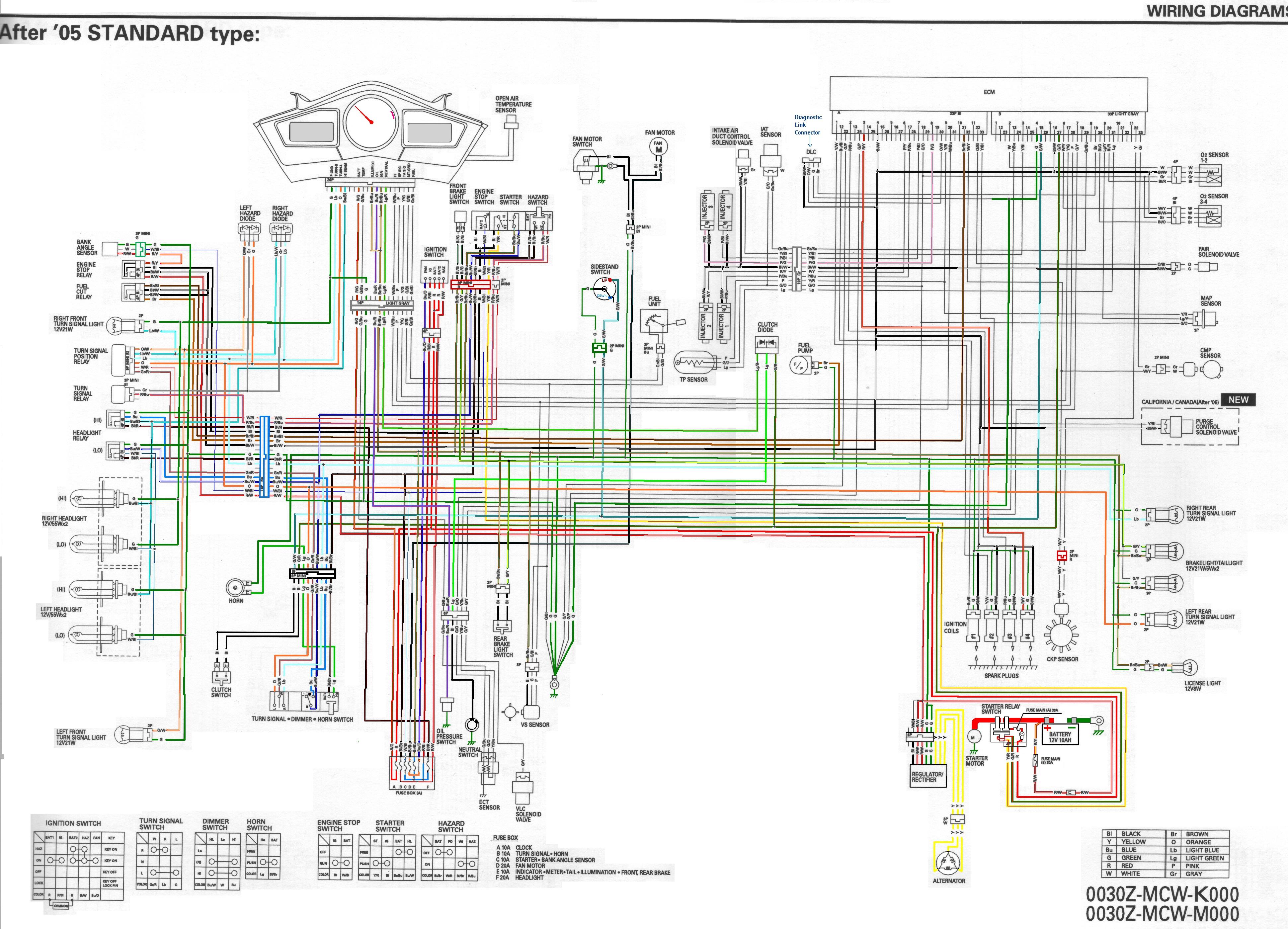
Ignition Switch to Off Kills power to sub Fuses C, E and F refer the attached drawing ( 2005 model should be similar to yours).
Loss of power to fuse C being the 12v power to the Kill Switch and the Bank Angle Sensor also knocks out the Engine Stop Relay to kill the Engine.
Engine Stop Relay is not being controlled properly by the sound of things.
Have you got the Service Manual? You can download it from this forum.
Do you have a multimeter?
If Yes then...
Suggest you follow the Kill Switch power path...refer attached wiring diagram.
1. Measure Voltage at the Engine Stop Relay on the Black wire there should ONLY be 12v on this wire when Kill Switch is in RUN position with Ignition to On. Activate the Kill switch a few times while monitoring the voltage. It might be easier to monitor this voltage at the 18P Blue connector located just forward above the L/H radiator, remove the left side cowl.
What do you measure every time you operate the Kill Switch?

-
1
-
-
I'm amazed at the engineering of this project, kudos to the OP. But with all the added hp of a Supercharger surely wouldn't every component within the engine, pistons, crank, transmission, clutch etc potentially be stressed beyond its design capability? Just wondering!
-
Just for a laugh!.....

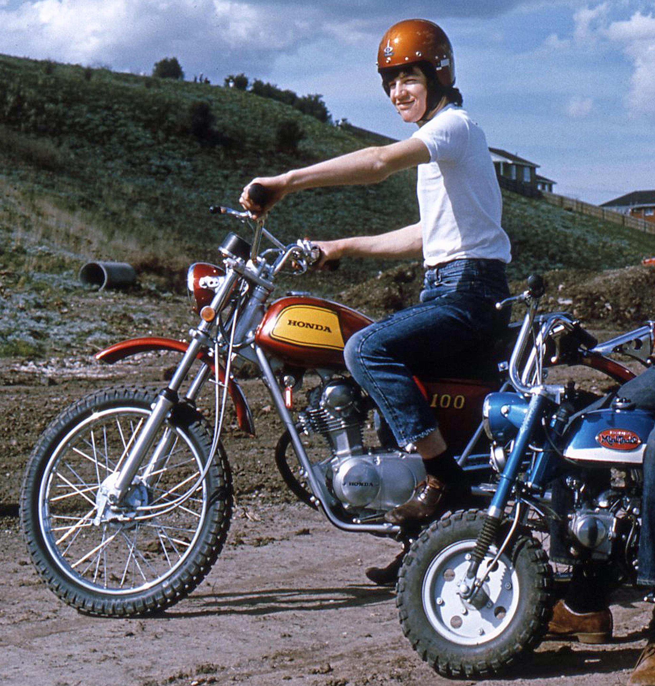
1972 - Yikes, 52 years ago!! My beloved Honda SL100, absolutely had a hoot with this bike. Worked three paper delivery rounds per week to save up for it. I'd really give this bike a work out and never had a fault with it. That bike won me over forever with Honda's build quality, reliability and durability. My buddies little Honda Mini Trail was also bulletproof. ATGATT...only partially back then.
Cheers

-
2
-
-
5 hours ago, JDMBird said:
Hey all, I've got a 1994 VFR that during a short day trip a few years back, suddenly died. I had already purchased a VFRNess and new regulator, so I went ahead and installed them. I found that the Main fuse had blown as well. I replaced the main fuse, and every time that I would go to try to start the bike, it would blow again. I swapped back to the original regulator, and there was no change. I let it sit for another year, and was able to get the starter to turn over for about 10 seconds this time, before again blowing the main fuse. I went through all of the wiring on the vfrness and ensured that all connections were good, however I am now at a loss as to what could be causing this fuse to blow. 99% of the time, it will blow at the press of the starter button. I should also note that the battery has been changed out for a fresh one as well.
Just to be clear....
1 - Was a blown Main Fuse 30amp in the Starter Relay the cause of the bike dying on your short day trip? OR has the fuse issue Only happened since the wiring change?
2 - And with the R/R unplugged. It still blows the fuse Only when pressing the Starter button?
3 - Your are absolutely sure, this fuse Only blows when pressing the Starter button, and Not just with turning the Ignition Switch to On?
4 - Assume the replacement fuse is a 30amp Fuse? Sorry, but need to be sure!
5 - Do you have photos or wiring diagram of the changes you've made?
My gut feeling at this stage is there's something strange going on within the Starter Relay when being energised. Independent checks on the Relay can be run after hearing back regards questions above.
-
On 4/16/2024 at 11:52 AM, mello dude said:
Saw Danno posted today on the ST-owners forum.... looks like he is busy working on getting a pilots license...
Hi Mello.
Thanks for the info. Saw his name on the member list. I don't want to join the ST-owners forum, but if you're on it? Can you send him a PM, tell him to get back to the real forum! VFRD misses him.
Cheers

-
3
-
-
6 hours ago, Kobo said:
Very tricky! With (mostly) everything plugged in, the fuel pump runs continuously with the plug bridged. (didn’t hook up fuel line since it was just a test for the pump. could be why it’s running continuously. not sure.) I swapped the hi beam relay in AFTER confirmation of fuel pump. Pump did not run with relay in.
Continuity check on FI light wire was good.
So far everything seems good. Unless there’s a vital piece that i’m missing… I can’t help but think ECU…
We're not done just yet.
1 - Ok. So I get from what you're saying. You still do not hear the Fuel Pump prime at switch on?
2 - Can you elaborate as to what isn't plugged in? Apart from the obvious light's.
"the fuel pump runs continuously with the plug bridged. (didn’t hook up fuel line since it was just a test for the pump. could be why it’s running continuously. not sure.)" That's exactly what should happen when bypassing the FCR! Fuel Pump runs continuously.
3 - Verify good continuity of the Brown/Black wire(FCR control wire) from the FCR to A21 (or possibly B18?) at the ECM.
Here's a test for the ECM and Fi Light.
Refer to chapter 5 in the Service Manual pages 5-7 to 5-8.
4 - Add a shorting link to the the ECM Service Check Connector as if you wanted to retrieve any historical Fault Codes. With Sidestand down and kill switch to RUN. Switch On Ignition. Does the Fi Light come On or flash a code? It should do one or the other.
5 - Looking at your photo again and seeing the ECM exposed as it is. Do a close inspection for any impact damage, are there any physical signs of cracks, on the ECM or its connectors?
6 - Check the wiring of the Ignition Switch. Does it have a pink wire and a diode mounted on the underneath of the switch like the photo attached? This diode and wire performs an ECM enabled and security function.
7 - And one Final Test, the end is near! Voltages measurement, Red meter lead to Battery Positive. Black lead to the Brown/Black wire for the FCR. Everything plugged in. Kill Switch to RUN, with Ignition to On, DO YOU MEASURE 12V FOR APPROXIMATELY 2 TO 3 SECONDS AT SWITCH ON?
Let's know how you get on with the above questions and tests. All 7 of them Please! This should determine if you do have a dud ECM.
-
1
-
-
Good report again Kyle.
Hmmm getting tricky!
Can you just re-confirm that - with everything plugged back in, at switch On, Kill switch to RUN, do you at least hear the Fuel Pump prime/run for 2 to 3secs?
If not, just for the hell of it swap the FCR with your Hi Beam Relay, does this change things?
Fi Light - Do a continuity check of the White/Blue wire from the Instrument Panel to (possibly!) A20 at the ECM. Refer above wiring diagram.
-
5 hours ago, styran said:
So @Grum,
Should I replace them?
I just replaced by buddies (the one with the electrical problem) CCTs at 41k miles. Mines only at 22k and starting to clack
Yeah mate. That does sound like the classic CCT symptom, with chain clatter up at the head covers, and from the R/H side.
Listen closely and determine if its from the front or rear cylinders.
Cheers
-
1
-
-
Good job glad you have it sorted. Will remember that one.
Corrosion on Starter Switch contacts = low voltage to Starter Relay coil.
A good coating of Ox-Gard on the contacts will help keep the corrosion away.
Just for info - "I bypassed the clutch switch to see if it made any difference and it did not"
The clutch switch was never going to be part of the problem because you had starting issues in Both of the starting modes, a Neutral Start and the In Gear Start(SS Up and Clutch in).
Enjoy the 8gen, it generally is super reliable in the electrical department.
Cheers
-
Well well. A Green/Blue wire! The wiring diagrams Are Correct.
And you wonder why you've made me a "Grumpy Grum"......Should be as obvious as the correct Green/Blue wire I'm seeing for Temperature Input Not a "blue with gray dashes" and that it took three requests for you check it. As for those gray dashes you mention I have no idea what they are for.
And why only now, you're admitting to having ordered a replacement ECT sometime back, after you stated on the other post (2000 VFR800 fuel pump no power) that you did the Service Manual tests and suspected it was faulty back then?
30.1 Ohms is Miles out of tolerance. You could have saved us all a hell of a lot of time wasting, sounds like another wild goose chase per the ECM saga, I'm convinced you knew about the blown ECM all along.
And this -
"BLUE 10P wire is blue with gray dashes good continuity." Question asked, continuity to What? You were looking at the Lb wire Light Blue - For the R/H Turn Indicator Light!
And this -
"item 8 You are incorrect the wire is not green/blue it is blue with gray dashes" Sorry not so! But correct if chasing a Turn Light fault.
Seriously, trying to sort out your problems via a keybord 14,000km away is near impossible (well for me anyway) when your feedback has been confusing, with very little clear info, jumping off track, or not answering questions, it just makes the whole interaction messy, difficult to follow, and time wasting.
As for the insult - "Grumpy Grum says he truly is the expert." I've never said that in my 67 years existence, I don't hold back or hide info from people and enjoy passing whatever helpful info I may have to help others, even You! I've worked with people who kept important, helpful info from others, a job security issue perhaps, that ain't me. But frankly I couldn't care less mate!
Enough said, good luck with it all, guess you don't believe this, but I hope you get that bike up and running ASAP. This time I'm definitely done.
Cheers
-
2
-
-
Refit the ECT Sensor plug. Measure at the 10P Blue connector between the pin you've located as going to the ECT and the Green/Black (Ground ) wire pin also on the Blue 10P connector.
WHAT RESISTANCE VALUE DO YOU MEASURE.?
And just for a third time - care to give an answer to what was previously Asked? ......
-
 1
1
-
-
13 minutes ago, n3n3 said:
Good morning and thank you for your continued support. Yes I have continuity on the yellow brick Road.
Great half an answer! And what was mentioned in Bold print, seems like you didn't read it.
-
 1
1
-
-
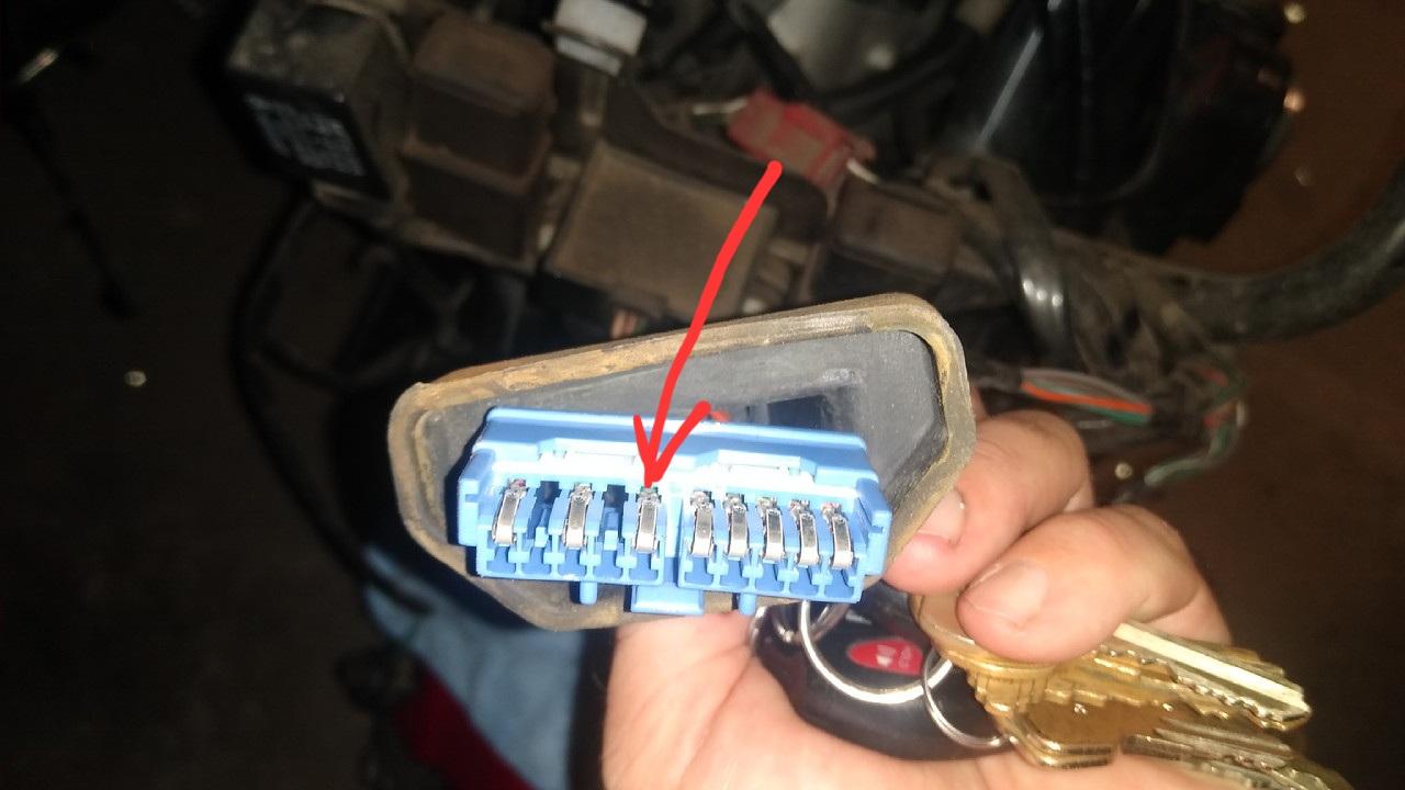
What is the colour of the wire at the back of this pin (Red arrow) of the 10P Blue Instrument Panel Plug? This is the Temperature input from the ECT sensor.
But wait there's more! Incase you need to check further........... Mapped out the PCB tracks and connection point for LCD Temperature Display. Just follow the Yellow Brick Road highlighting, (ignore red arrows and comments lower part of picture.)
-
1
-
-
11 hours ago, n3n3 said:
item 6 Yes I have already stated I have continuity in all 3 wires
item 8 You are incorrect the wire is not green/blue it is blue with gray dashes
item 9 I don't see that one
Thanks for your help maybe it's just how you respond but you sound very condescending no reason for that. We are all fellow riders and Im trying to learn. Thanks again
8. So you're saying the Green/Blue from the ECT somwhere changes to a Blue/Gray at the Instrument Panel? AND that doesn't appear on the Pre or Post 99 Drawiings!
AND if you look closely, unfortunately the colored drawing shows a Gray/Blue wire........That is incorrectly colored and is actually a Gray/Black (Gr/Bl) wire and goes to the Fuel Sender. However, with BOTH drawings there is NO reference to a Blue/Gray (Bu/Gr) wire amongst the 17 Instrument Panel wires?
The ONLY two Blue (main wire color) wires at the Instrument Panel are a Blue/Red = Oil Pressure Light, and, Blue/Black = Hi Beam indicator Light.
I don't have a 5th gen, never have, so I can only go by relevant drawings be they Right or Wrong!! So it's impossible for me to verify this Blue/Gray wire you talk of.
9. Go back and check I added the number 9 to that paragraph this morning to draw attention to it.
"you sound very condescending no reason for that". Short memory mate, and yes I do have reasons. And still no mention that you have replaced the ECT. I hope you fitted a genuine OEM and not some Chinese cheapy!
However, you've got tons of info provided which should hopefully resolve your issue, you just need to use it, along with the Service Manual and wiring diagram.
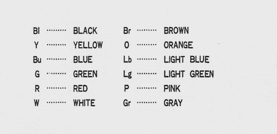
Info - Wire coding and drawings.. Eg A Bu/Gr - Blue is the Main wire colour, Gray is its stripe being the trace. No trace = a solid color wire. See attached wire table.
AND - I do mean it, Good Luck and hope you have it resolved soon.
-
1
-
-
Hi Skids.
That's a real bummer m8. I feel your pain! Yep that horrible point of no return, trying desperately to recover it or at least lay it down gracefully.
I remember years ago doing damage to my leg femoral nerve by saving a topple over, the bike back upright without hitting the deck, but bloody hell, the resulting nerve damage was painful for weeks.
You're definitely No "Muppet" m8, shit happens!. Given my weight at the moment I feel a little bit Miss Piggy ish!
Hope you and the bike are mended ASAP.
Take Care.
Cheers.
-
2
-
-
1 hour ago, n3n3 said:
Ok, so this is the correct wire diagram. Thanks thought I was going crazy!
And to avoid repeating myself yet again......
Refer Items 6,8 and 9 above!
Info - Wire and trace colour at the ECT may have faded due to heat cycles.
-
1
-
-
6 hours ago, Presson said:
This is all quite mysterious as the colours don't seem to reflect the appropriate version diagram; assuming you have got the right one for your model. Could the wiring loom have been swapped out for an alternative?
Hi Presson.
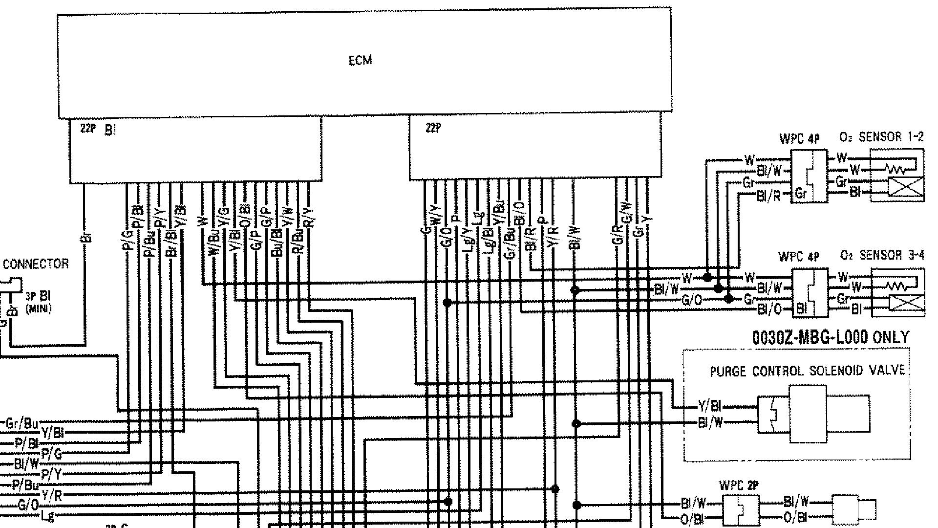
Assuming his wiring loom hasn't been swapped out, his version is the After 99 model having O2 sensors which are wired into the Gray connector. However the ECT sensor wire colors remain the same between the two versions.
Far easier working with the earlier nice Hi Rez colorized drawing for 99% of fault finding, compared to the correct but Black and White after 1999 version.
See attached, sorry no color version available. Gray connector is on the Right.
-
1
-
-
21 minutes ago, Evo4g63t said:
Don't suppose anyone has a list of error codes
Sorry the 2010 Service Manual I have doesn't cover the DCT version. Hopefully someone will chime in for you.
-
1
-

.JPG.e854512fe5c890a30f6f19befeb1f2b4.JPG)
Starting up issue
in Sixth Generation VFR's
Posted
Sounds like you might have a bit of stiction with the Wax unit linkages, etc.
Try cleaning and lubricating all linkages, a spray of some WD-40.
See if that makes any difference.
You might also benefit from a Starter Valve Synch procedure.
While you're in that area. Pop the vacuum hose off the FPR Fuel Pressure Regulator, check the hose is dry and no weeping of fuel from the FPR vac hose fitting. Weeping fuel = Ruptured diaphragm.
And.......Download the Service Manual from the forum if you don't already have it.