BiKenG
-
Posts
645 -
Joined
-
Last visited
-
Days Won
6
Content Type
Forums
Profiles
Gallery
Blogs
Downloads
Events
Everything posted by BiKenG
-
From the album: RVT1000 SP-2
-
Ah, so clearly the carbs are a larger bore than the injectors. Hmm. Durbahn used GSX-R 750 injectors which are larger and may therefore be better. But, I am more interested in mid range torque and ride-ability than outright power, so the smaller injectors might be a better bet. They flow enough for acceptable power on the 800, so really, they should be enough on this 750. Re-joining the bodies for the different spacing and angle will be one problem, but the intake rubbers will be another. Durbahn had some specially made. That'll be something to consider at a later date. In fact, if I use the throttle bodies with the same OD as the carbs, I could use the 750's original intake rubbers. You know the next question John. Could you possibly measure those ODs? How well would a throttle body fit in the 750 intake rubber? BTW, this is not a short term project. I also have several others I'm working on and this is more a case of as and when I get time. So don't expect rapid progress.
-
The dash is really simple and the ECU doesn't care about whether it's connected or not. I've not decided on dash for this bike yet, but won't be OEM VFR. I'm building this from a separate engine and frame (that I already have), so I'll just buy the bits I need rather than butcher any existing bike. The FI system requires a CranK Position sensor and a CaM Position sensor. The former will be very accurate to determine the exact position of the crank. The latter will be far less so, but is required to establish on which part of the stroke the engine is on as that cannot be determined from the CKP sensor output which is used to provide the ignition timing. The ECU can simply control the timing of the spark relative to the CKP sensor output, but also knows when it's TDC and when it's top of the exhaust stroke from the CMP sensor output and in this way there's no need for any wasted spark. What I'm not sure about is how it decides when to open the injectors. That's less critical than ignition timing and could use the less accurate CMP sensor output, but I think it's more likely that the CMP sensor is only used to determine the stroke and it's the CKP sensor output that is used to accurately determine when to spark and/or squirt. However, to a certain extent it's irrelevant. There will need to be CMP sensor and I'll need to figure out how to add that. Durbahn's site will help there as he's done it for the RC30 and a 400. In any case, assuming the ignition pulse of the 750 can be used as the CKP sensor output the CMP sensor is the only one that needs to be added to engine. I was thinking of using an 800 fuel tank, which has an internal pump of course. Might drop straight on. Anyone tried this? I'm not imagining any of this will be simply swap and fit from other bikes. I WILL have to manufacture parts for the throttle bodies assembly and the cam will need welding etc, but I have the equipment. There are various ECU options if I don't go with the 800's. Durbahn used Motec and could provide ready made working maps to start from, but there are others, although probably have to start from scratch creating the maps. I still think the 800 ECU and a PC would be the simplest.
-
I thought about and looked into that, but it wouldn't be trivial. Cut the S/A pivot boss off the back of the 800 engine for starters and then most of the mounting points don't line up so quite a lot of reworking the frame to make it fit. Even then you'd have to mess with the airbox, so no advantage there. But also, I like the idea of the 750 engine. Nicely symmetrical compared to the 800 and I think a fun project to inject it. Don't get me wrong about the 800 engine. I do like that also and have other projects going on involving a couple of those, so in some way, I also wanted this to be a 750 to differentiate it.
-
Hey Keef, I've been telling him that for years now.
-
I'm thinking about injecting an RC36.2 and hoped we could have a good technical discussion about it here. First of all:- I realise that the RC46 throttle bodies won't just drop on. Durbahn has injected an RC30 and a 400. However I believe he used the Motec system. I have also read (here?) of someone using MegaSquirt on a V4. But... It seems to me that the RC46 injection is way closer to what is required than either Motec or MegaSquirt and MUST be cheaper than either of those. So I'm pondering the possibility of modifying the RC46 throttle bodies to fit the RC36 and use the RC46 ECU, with a Dynojet PC or Rapid Bike module to 'tune' the ECU's delivery to suit the different motor, although I'm thinking that it probably would actually run without either. Not well enough to use, no doubt, but it would sure help development if you have something that runs. The throttle bodies will take a lot of modification, but that surely must be easier than trying to manufacture something from scratch. They'll need to be split apart, mounted in the correct relative position and suitable linkages and fuel pipes made. Tricky, but as I said, has to be easier than starting from scratch and there would be a readily available wiring harness too - RC46. Another very tricky task would be to add a Cam sensor probably requiring accurately positioning and welding something to a cam. However, maybe the existing output from the RC36's Ignition sensor could be used as the CranK Position sensor. Everything else is external and can be simply added to the bike, plugged into the RC46 wiring harness which would have all the right connectors. I notice that the 5th Gen FI system uses an atmospheric pressure (BARO) sensor, but that is no longer used on later VFR's, nor any other bikes I briefly checked. But if the ECU needs it and the wiring harness has the connection (yes to both), then the BARO sensor can be plugged in and used. So there's 3 major issues I see here. 1. Modifying the RC46 throttle bodies to suit the RC36 intakes. 2. Creating a Cam Position Sensor 3. Using a Power Commander to modify the ECU's control sufficiently to suit this engine. I'm pretty sure 1. can be done. 2. can definitely be done, but I'm less sure about 3. I see no actual reason why not, but it would largely depend on the range of adjustment afforded by the add-on management module (PC or other). Please don't ask WHY? No point arguing about that. But apart from that, what do others think about this?
-

Single Nut Conversion Vfr800 Hrc Rc45 Style - One More:-)
BiKenG replied to VFRRR's topic in Modifications
Very kind of you John, but I've found a new axle at decent price, so I'll not have to trouble you for one of yours, thanks anyway. Still need the suspension link though. Meanwhile, arranging to mount the wheel in the lathe and then also on the mill is making my head hurt. -
Single Nut Conversion Vfr800 Hrc Rc45 Style - One More:-)
BiKenG replied to VFRRR's topic in Modifications
Thanks for that. The RC axle bolt is about 206 long which explains why it looks too long in the NC axle. So in fact it IS too long. Rats :-( -
Single Nut Conversion Vfr800 Hrc Rc45 Style - One More:-)
BiKenG replied to VFRRR's topic in Modifications
I have determined that opening up the centre bore of the wheel to fit over the full length of axle is the way to go and I'm just working on a way to mount the wheel in the lathe in order to accomplish this. However, the relative lengths of axle have thrown up a problem. If I insert an RC bolt into the NC axle, mount an RC wheel and a spacer, it is clear that the axle is nearly an inch too long. So either the RCs' wheel is much thinner, or their bolt is quite a bit longer and I suspect the latter. Anyone got an NC axle bolt they could measure? -
Single Nut Conversion Vfr800 Hrc Rc45 Style - One More:-)
BiKenG replied to VFRRR's topic in Modifications
I believe the NC axle will work in the RC36 S/A and I suspect the lack of cush drive is the reason for it being shorter. But you apparently do need to machine the axle slightly to shift it slightly left in order to align the wheel correctly. Mohawk is the expert on this and has it all figured out for when he did it on his bike. In order to use the RC45 conical spacer, the axle needs to extend through the wheel as the spacer centres the wheel to that end of the axle. If I cut the axle shorter to allow the wheel to fit, the conical spacer won't be able to engage on it. The alternative is to enlarge the bore through the wheel so the axle fits through. But my current feeling is to cut down the axle and just use the 400 flat spacer. Of course ti could all change tomorrow. -
Single Nut Conversion Vfr800 Hrc Rc45 Style - One More:-)
BiKenG replied to VFRRR's topic in Modifications
Yes I have an RC45, but apart from it being tucked away at the moment and hard to get to, I'm not sure I want go that route. Specifically I think it's because I have a couple of 400 spacers and hate the thought of not using one of those and buying something else instead. Unless someone else found they had an RC45 one available... In fact, the raised ridge on the inside of the 400 spacer is an almost perfect fit into the outside of the RC36.2 wheel. Although the wheel has a tapered centre hole like the RC45. the 400 spacer is a snug fit. I reckon with the paint removed it wouldn't even need any machining for the 400 spacer that would grab the wheel nicely when the nut was tightened. So that's probably the route I'll take. I do need to machine out the inside end of the wheel centre bore (currently 50mm) to fit over the axle boss (needs 51mm) however and getting the wheel mounted that way around in the lathe will be interesting. I did measure the axle and the PCDs are as follows:- Drive pins = 85mm Wheel studs = 100mm Disc mount bolts = 110mm I guess using the different PCDs makes sense for OEM, but if they were the same it would make this job a lot simpler. -
Single Nut Conversion Vfr800 Hrc Rc45 Style - One More:-)
BiKenG replied to VFRRR's topic in Modifications
Excellent info John (JZH) thanks. My concern at the moment is fitting an RC36.2 wheel to the NC30 axle. As you mentioned above, the axle is too large to fit through the wheel. So it's modify the wheel or shorten the axle. Since I'll need to modify the wheel anyway, I'll probably do both. I will need to turn out the wheel's centre bore on the mount side to be a snug fit over that boss and also turn the outer edge of the bore so that the 400 'not cone' spacer fits nicely or I could use an RC45 cone spacer, if I had one. But I don't. I have a couple of 400 type spacers though so that's probably the way to go. Unless anyone has an RC45 cone spacer going spare? Ideally wanting to swap for a 400 one. As has been mentioned before, I will need to plug the original bolt holes in the outer surface of the wheel, but I could then make some large drive pins that would locate into the wheel's bolt holes in the inner mount surface and modify the axle flange to fit these pins at the 100mm PCD, as John has done above with actual wheel studs, although I'll mount my special drive pins instead. It's a pity Honda didn't use 100mm PCD for the drive pins. That would have been just soooo convenient. Hmm, what's the disc mount hole PCD? If that was 100mm... Looking at the pictures it looks slightly larger (damn), but I need to measure it to be sure. That would also be extremely convenient. Next problem is how to mount the wheel in my lathe and that's assuming it's even big enough. Time to find out. -
Single Nut Conversion Vfr800 Hrc Rc45 Style - One More:-)
BiKenG replied to VFRRR's topic in Modifications
I'm trying to put together a single nut fixing using Honda's central axle bolt. I have an RC45 axle bolt and it appears to fit into the NC30 axle although the splines don't exactly slide in easily and will need some tapping to go fully home (they're totally dry having only just been de-greased). I'm guessing that's normal. However, the bolt then protrudes about 2" from the end of the axle. Should it be this long? Means the wheel and washers have to be much thicker than I would have expected. I've got nothing to which I can compare it. Can anyone recall how much the bolt sticks out of the axle or has a 400 axle they can measure for length? How is a 400 wheel centred? There's no RC45 style cone spacer to centralise it on the axle, so what does? Is the idea that it is a snug fit over the axle and that's sufficient. The fancy spacer under the nut then would be just a big washer. Or does that spacer somehow help even though it's not going to be as good as the RC45's cone spacer. Or does the wheel sit snug on the boss at the centre of the flange, with the drive pins just there to stop it rotating? The RC45 uses its cone spacer for this, but I just cannot see quite how the 400 achieves the same centralisation and I don't have all the 400 parts to be able to work it out. Anyone familiar with the 400s? -
Single Nut Conversion Vfr800 Hrc Rc45 Style - One More:-)
BiKenG replied to VFRRR's topic in Modifications
I had thought it could be welded all the way around the axle, but I now realise that's not really possible as the 'adapter' is pushed into the axle right up to the thread. So as far as I can see from the photos, holes must be drilled in the axle and the adapter welded to the axle just around each hole. Can't have too many holes, obviously. The only other way would be to cut the axle shorter and weld that shortened end to the adapter around the full circumference. The axle would just need shortening sufficiently to provide enough space for the weld. But making sure the adapter is pushed in to the correct depth would be trickier. Anyone actually installed this adapter and could comment? -
Single Nut Conversion Vfr800 Hrc Rc45 Style - One More:-)
BiKenG replied to VFRRR's topic in Modifications
Surely you mean wheel side? The sprocket side uses M38 x 1.5 (or M35 if not single nut wheel fixing). I took a chance and ordered the Ti wheel nut that was specified for the 400s but not the RC45. Should be here today, but good to know I made the right choice. -
Single Nut Conversion Vfr800 Hrc Rc45 Style - One More:-)
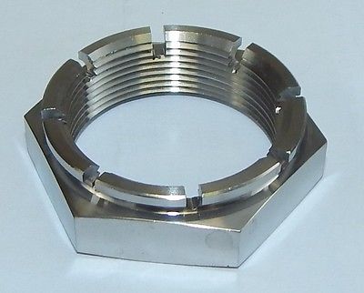
BiKenG replied to VFRRR's topic in Modifications
I love Titanium. Here's the Triumph nut I just bought from compeng24. He is intending to produce Ti clips to go with them, but might be a month or 2. In conjunction with Titan Classics conical spring washer this seems like a perfect solution for the driven side of the axle. TC also offer a lot of other useful Ti stuff like h/bar lever pivots, rear wheel drive pins and steering stem nuts. Just have to wait a while till I can afford those. Did I mention, I love Ti.
-
Single Nut Conversion Vfr800 Hrc Rc45 Style - One More:-)
BiKenG replied to VFRRR's topic in Modifications
Yes of course it's the total area of pistons MOVING IN THE SAME DIRECTION. But assuming the same piston size, a single piston in a sliding caliper is EXACTLY the same as 2 pistons moving in opposition (i.e. fixed caliper). For the latter, the area you'd use for any calculation would only be for ONE piston. The sliding effect of the caliper means essentially the same amount of fluid has to be moved in each of these different designs. There are of course other considerations that make the sliding caliper less than optimal, but they're cheaper to make hence why we still see them being used. I just bought a couple of CRF style master cylinders to try out. Only £6 each on eBay - new. I know, Chinese manufactured (and supplied), but you can't knock the price and I'm sure they will actually work as well as I need - as long as the size is suitable. -
Single Nut Conversion Vfr800 Hrc Rc45 Style - One More:-)
BiKenG replied to VFRRR's topic in Modifications
I've just ordered the Triumph wheel nut which at M38 x 1.5 is the correct size for the Honda's driven side axle nut. Although the Honda style nut is available from Titan Classics, I just hate the idea of having to bend a part just to make it do its job, especially if you want to be able to re-use it multiple times. Shame on Honda for employing such a crummy idea. The Triumph one however is castellated and with some drilling of the axle I'll be able to use the Triumph clip on it too. Neither are flanged, but I don't see that as being a problem. There is supposed to be a spring/conical washer underneath that nut and using a flange type nut wouldn't obviate the need for that spring loading. But Titan Classics have those conical washers in Ti, so all's good. In fact TC also have the wheel nut R clip in Ti. So the RC45 wheel nut is M18 x 1.5, but what about the NC30 and 35? I suspect they are the same, but I cannot seem to get any confirmation of that. -
Single Nut Conversion Vfr800 Hrc Rc45 Style - One More:-)
BiKenG replied to VFRRR's topic in Modifications
Looking further at axle nuts, it appears Ducati use M33, M38 or M48. So no matches there -
Single Nut Conversion Vfr800 Hrc Rc45 Style - One More:-)
BiKenG replied to VFRRR's topic in Modifications
Hey keef, I see you're using Ducati (style) nuts on both ends of the axle. Is that because the nuts fit the Honda axle (in which case, which axle) or are you using a Ducati axle? -
Single Nut Conversion Vfr800 Hrc Rc45 Style - One More:-)
BiKenG replied to VFRRR's topic in Modifications
I also think the RC45 uses the same thread on its axle bolt as the NC30 and 35. But I've not confirmed that 100% and I don't want to waste the money on a nice Ti nut if it's wrong. Are you looking for the LH/driven side axle nut? That's the M38 x 1.5. Titan Classic have those that can be staked like the original, but buy from their website as it seems a bit cheaper than their eBay store. If you don't want to stake the nut into the slot in the axle (like I don't) do what Mohawk did and drill the lip of the nut and the axle so the Ducati (or some other) clip can be used. -
Single Nut Conversion Vfr800 Hrc Rc45 Style - One More:-)
BiKenG replied to VFRRR's topic in Modifications
Maybe a silly question, but why did HRC use a LH thread for their large single wheel nut? Also, do Ducati use LH or RH wheel nut thread and is it the same dia. and pitch as VFRRR and HRC? Does a Ducati nut fit the M38 x 1.5 thread on the driven side of the axle? Does the NC30/35 wheel nut fit the RC45. So is the thread on the end of the internal axle bolt the same for both bikes? -
Rear Wheels/tires, The End All Discussion
BiKenG replied to dallasb's question in Modification Questions
Can I ask what you (rc4six) did with the VFR. It's a 3rd Gen wheel that is normally located and driven by the wheel mount studs and nuts - which are no longer used. I assume you used a 400 axle, but how did you match the wheel to the drive pins? Did you have to machine the back mount face of the wheel to accommodate the drive pins? -
Single Nut Conversion Vfr800 Hrc Rc45 Style - One More:-)
BiKenG replied to VFRRR's topic in Modifications
PPS, Chris I'm surprised at you. Single piston sliding caliper or twin opposing pistons, makes no difference. Only the piston diameter is relevant. I have a small special caliper previously used on my RC45 which I hope to use on my 800 project. It's another small caliper with twin opposing pistons and I'm thinking of trying the CRF Master Cylinder also. I'm sure it would work well (enough). -
Single Nut Conversion Vfr800 Hrc Rc45 Style - One More:-)
BiKenG replied to VFRRR's topic in Modifications
I was hoping VFRRR has at least one more of these sets as I could really do with one for my forthcoming V4 project. No response to PM though. If he could let me know (and hopefully sell me one) I'd be grateful.