


BartmanEH
-
Posts
172 -
Joined
-
Last visited
-
Days Won
1
Content Type
Forums
Profiles
Gallery
Blogs
Downloads
Events
Everything posted by BartmanEH
-
From the album: Gear Position Indicator
-
From the album: Gear Position Indicator
-

Version v3
11,456 downloads
As originally made available by HispanicSlammer, this manual first came out for the 2002 model (first 6th generation model year). Not much has changed with respect to servicing the 6th gen VTEC since it was introduced in 2002. By-and-large, this manual applies to all 6th generation VFRs for years 2002 to 2011. There are only minor differences in some later years, most notably starting in 2006, with changes to VTEC engagement RPM and the wiring harness. All the hard work for this scanned version was done by an unknown source. The actual manual part is not searchable since it is a compilation of page scans only. I was tired of scrolling around the huge document trying to find what I needed. So I spent a few hours generating bookmarks. This version has bookmarks for all the subsections for each major section in the manual. The first page for each major section lists all the subsections and these each now have a bookmark for quick and easy document navigation. If you enable bookmark searching in your PDF reader - and most PDF readers support this - you can then search for major terms and subsections and get search results in the bookmarks. Remember, this Factory Service Manual is far from perfect. Firstly, it presumes you have a reasonable level of mechanic/shop experience. Secondly, it contains many errors. Not just typos, but erroneous information. Some of it was fixed in errata releases in subsequent years but not all of it (trust me, I've checked). I strongly advise that you search for relevant topics, review them and post any questions you may have in this most excellent of forums, VFRD, prior to performing your own major servicing of your VFR. There are amazingly helpful members here and a lot of great How-To posts. Enjoy and be safe! P.S. new version v3 has fully searchable text thanks to Adobe Acrobat's amazing "recognize text" OCR feature which has the added bonus of deskewing the page images as well as generating fully searchable text! -
Replacing the brake fluid in my ABS model--that was really something. There are no less than 7 bleeders! It took 3 people to do it. The first person operated the level/pedal and refilled the reservoirs as required, the second person opened/closed each bleeder in succession and the third person was required for the one bleeder that required manually pumping the second master cylinder on the left front brake. I will definitely be looking into SpeedBleeders or Stahlbus Bleeders for the next time to simplify the process. In the meantime, I thought I'd document the procedure I came up with for doing the brake fluid change. The Service Manual has a few errors in it e.g. tells you to remove and tilt up the fr. left caliper but never tells you to reinstall it and it tells you refill and reinstall the lever reservoir cover but then goes on to bleed a few more bleeders that use fluid from that reservoir. There's been a lot of posts about what the correct order is and people having problems with spongy brakes which turned out to be because they forgot a bleeder or did it in the wrong order. The following system worked very well for the two 6th gen ABS models I did last fall. It's not a tutorial per se; there's no pictures and no details (for that, you can look up the excellent HS pictorial-based tutorial or the new Jay-D tutorial) and I didn't include obvious steps like removing the seat etc. Note: although recommended in the FSM and elsewhere, I don't remove the front left caliper for fluid replacement—only when I need to bleed air which is normally not required for fluid replacement. I just manually actuate the SMC with the caliper in place. Works well and you don't risk wearing out the mounting bolts or squeezing the pads together making reassembly difficult. In fact, I don't remove the rear wheel or the rear caliper anymore either! I made an overall hydraulic system picture by combining elements of several pictures from the Factory Service Manual: This took a lot of image manipulation to create but it was worth it. This overall view of the braking hydraulic circuit helps to visualize how the system works. For example, it clearly shows that the Second Master Cylinder (SMC) is refilled from the rear reservoir with the pedal. These are the steps you need to take: - Turn handlebar all the way to the left to level Lever Reservoir - Open Lever and Pedal Reservoirs - Remove old fluid from Lever and Pedal Reservoirs - Fill Lever and Pedal Reservoirs with new fluid - Remove the rear wheel (not necessary!) - Remove Rear Brake Caliper and install on top rear of Rear Brake Disc at 10 o'clock position (not necessary!) - Maintain fluid level in both Reservoirs at all times, check between steps below Operate the Lever during bleeding of the initial two bleeders in the following order: Lever Brake Line: Master Cylinder to Front Brake Caliper [1] Left Front Brake Caliper outer (upper) bleeder (use Lever) [2] Right Front Brake Caliper bleeder (use Lever) - Refill Lever Reservoir as required to Upper Level Mark - Close Lever Reservoir (done with this reservoir) Servo Brake Line: Second Master Cylinder to Servo Proportional Control Valve NOTE: this bleeder (even if it's a SpeedBleeder) must be closed after each manual activation of the SMC; [3a] open Servo Proportional Control Valve bleeder (left/battery side) [3b] manually actuate Second Master Cylinder at Left Front Caliper [3c] close bleeder (if you don't close the bleeder or SpeedBleeder on SPCV, the rear pedal will not force (refill) the SMC back out very effectively) [3d] use Pedal to recharge Second Master Cylinder (SMC) repeat [3a]-[3d] several times Servo Brake Line: Rear Proportional Control Valve to Rear Brake Caliper [4] Rear Brake Caliper Center bleeder (use Pedal) Operate the Pedal during bleeding of the remaining three bleeders in the following order: Pedal Brake Line: Rear Master Cylinder to Rear Proportional Control Valve [5] Rear Proportional Control Valve (right side) bleeder (use Pedal) Pedal Brake Line: Rear Proportional Control Valve to Rear Brake Caliper [6] Rear Brake Caliper Outer bleeder (use Pedal) Pedal Brake Line: Rear Master Cylinder to Left Front Brake Caliper [7] Left Front Caliper Center bleeder (use Pedal) - Reinstall Left Front Brake Caliper (if removed) - Reinstall Rear Brake Caliper using new mounting bolts: 2 X 90131-GAA-000, BOLT, FLANGE (8X25) (torque 23ft-lbs) (if removed) - Refill Lever and Pedal Reservoirs as required to Upper Level Marks - Close Lever and Pedal Reservoirs - Reinstall rear wheel (torque 80ft-lbs) (if removed)
-
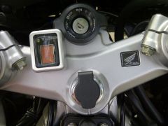
I currently have the Acumen GPI installed. It's great and sunlight readable but it is quite laggy - takes a while for it to display the gear. Anyone have the luxury of a direct comparison between the Acumen GPI and the new GIPRO DS version GPI? Is the new GIPRO DS really that much faster?
-
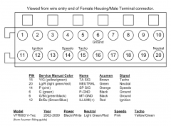
Hey DanY1, what did good 'ol Tighwad say? I'm thinking the same thing you are - work up a mod that doesn't involve hacking up the factory wiring. Hey coderighter (thanks for the BMC filter, BTW), even though my Speedohealer is only making an 8% correction for my stock setup, is it possible that the bike will behave better if I make the mod you've suggested? Even small gains in ridability at small throttle openings are welcome. I do annual starter valve syncs and have a PCIII+O2elims both of which have gone a long way to making the bike behave nicely. If doing this mod would help in even the slightest way, I'd do it. Maybe the ECU is happier all around with the stock signal inputs.
-
From the album: Combination Meter
© ©vfdiscussion.com
-
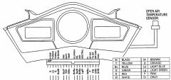
From the album: Combination Meter
© ©vfdiscussion.com
-

From the album: Avatar & Signature
-
Starter Valve Syncronization - VTEC
BartmanEH replied to HispanicSlammer's topic in Maintenance Guides
Now see? I have a real problem with all this. First of all, hooking up the MAP sensor to the flapper vacuum line is probably not going to work because that vacuum line is controlled by a solenoid that is RPM based. I haven't thought is through but it's possible that there's no vacuum on that line at idle and that's why the MAP sensor wasn't happy. I've always done my starter valve sync with the MAP sensor connected and have always managed to get what I thought was a good sync alignment. I should clarify and point out that with my homemade manometer setup, I have an extra T so I can hook up all 4 cyl's and the MAP sensor simultaneously. It's getting real system vacuum and maybe that's why it works for me. The "book" may say to leave the MAP sensor disconnected because they know that the standard manometer jig only has 4 ports and doesn't allow the MAP to be hooked up and get al system vacuum. I've also never used an electronic tach - it couldn't possibly matter that much. Furthermore, I want the sync perfect where my idle normally is which is a bit higher than 1200 and more like 13-1400 to help with throttle response etc. So, like BR, I'm looking for some consensus here about whether to keep sensors hooked up or to go "by the book" and keep some disconnected like the MAP sensor. After all, the book's not perfect or at least not very complete in the story it tells. -
Starter Valve Syncronization - VTEC
BartmanEH replied to HispanicSlammer's topic in Maintenance Guides
BaileyRock, dude... Sorry if I misled you to a small disaster with the ATF suggestion. Works great in homemade manometers. I didn't know you had Motion Pro. -
Starter Valve Syncronization - VTEC
BartmanEH replied to HispanicSlammer's topic in Maintenance Guides
If you're getting air bubbles, my experience tells me that you have a leak. In the first version of my homemade manometer, I got streams of air bubbles because of leaks around the T's. I don't know how repairable your manometer is though. -
Starter Valve Syncronization - VTEC
BartmanEH replied to HispanicSlammer's topic in Maintenance Guides
Yeah, sounds like your manometer isn't damping the pulsing well - maybe only on the cyl #2 line. You should make one, it's not so hard. -
Starter Valve Syncronization - VTEC
BartmanEH replied to HispanicSlammer's topic in Maintenance Guides
I use ATF in my homemade manometer (description) because: - It has a high viscosity so it moves slowly and acts as a natural damper - it is red so it is very visible - it won't likely harm the throttle body or engine if it accidentally gets sucked in (not likely anyway with the long hoses I use - it's cheap and readily available -
Starter Valve Syncronization - VTEC
BartmanEH replied to HispanicSlammer's topic in Maintenance Guides
Last time I did my starter valve sync, I connected up everything I could including the IAT and MAP sensors (but blocked of the PAIR) and seemed to be able to sync them quite well. So what is the consensus here regarding the MAP sensor? Connect it or disconnect it for starter valve sync? For my homemade manometer (post about starter valve sync with homemade manometer), I have a tee installed in one of the lines so I can connect up all the throttle bodies AND the MAP sensor all at the same time. Seemed to work for me. Thoughts? -
From the album: Combination Meter
© ©vfdiscussion.com
-
From the album: Combination Meter
© ©vfdiscussion.com
-
Just Installed Power Commander 5 On My '06!
BartmanEH replied to coderighter's topic in Modifications
I'm emailing with Dynojet right now to get more information about PC Vs and older VFRs. I have another question for coderighter. Since the PC V supports different maps for each gear, and your post says "separate maps for every gear (more on this later)", are you actually using this feature? The VFR does not have a gear position sensor so I'm wondering how this could be used. -
Just Installed Power Commander 5 On My '06!
BartmanEH replied to coderighter's topic in Modifications
I'm still confused... will the PC V for the 2009 VFR work on the 2006 model out-of-the-box? i.e. has the right harness connectors etc.? -
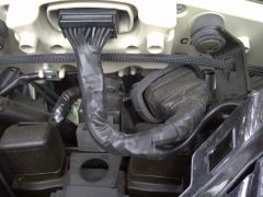
Air box anti-critter screen modification
-
-
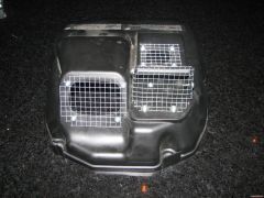
From the album: Critter Guard
© ©vfdiscussion.com
-
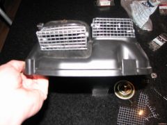
From the album: Critter Guard
© ©vfdiscussion.com
-
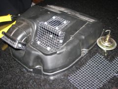
From the album: Critter Guard
© ©vfdiscussion.com
-
-
Adam30 said ((My velocity stacks are short/tall in front and tall/short on the rear head. Ive double checked this a couple times, since thats how the Honda service manual illustrates they should be.))... Are you sure about that? Mine are short in front and tall in the rear. If you look at the 2002 VTEC service manual, it's not clear about this. It shows 4 stacks and some are rotated which may make them appear taller/shorter but it's not clear where they go. However, if you look at the VFRD Parts List and navigate to the Air Cleaner, it shows 2 part numbers and they are the one part number in the front and the other part number in the rear. I'd say that clearly indicates that they're supposed to be short in front and tall in the rear. Maybe this is the source of your trouble?

