


Tightwad
-
Posts
1,689 -
Joined
-
Last visited
-
Days Won
1
Content Type
Forums
Profiles
Gallery
Blogs
Downloads
Events
Everything posted by Tightwad
-
Still got non-black wheels? Wanna trade?
-
 I do like the Black bike.....why does Red have to be faster??
 -
Producing A Fix For The Regulator/rectifier Wiring Issue
Tightwad replied to Tightwad's topic in Modifications
I have ordered the items for the first test batch. I will make 3 kits to start. I have decided to go with option #2, which is a piggy back into the existing harness. Talus suggested this, and I like the idea of two systems working together which in the end gives greater strength. This option solves the "what do I do with the open plug" problem I envisioned as well. The kit will come with: 2-20Amp fuses, one for the original 30Amp fuse holder, and one for the new fuse holder 1-Wire Harness to augment the existing setup, fully fused and relayed 1-set of directions with pictures to make it so simple my wife will be able to do it The only tools needed for install will be: fairing removal tools (allen wrench and small screwdriver for the plastic pins) 8 MM 1/4 drive socket/nutdriver on extension (wrench would work but might be harder) 10 MM Wrench/Socket basic knowledge of anatomy (male/female difference) A multi-meter would be helpful for testing the install, if you don't have one I can send one for $15 more that will do the job (I use it as a voltmeter on my bike) I will have photographs as soon as my connectors, relays, wire, etc arrive. Basically the layout will be this(for those who are interested): From the Positive terminal of the Battery, an 8 gauge wire(might be 10 gauge) into a fuse. From the fuse, an 8 gauge wire will run to the R/R area (inside split loom tubing for heat/abrasive protection. The run will most likely be made under the tank, for ease of installation. From here it junctions into 3 wires, 2 wires piggyback onto the existing Red w/White wires on the R/R plug. One wire goes to the Relay. The two Green wires will have leads attached at the new connector, and will be joined by the relay ground on a terminal that will bolt onto/under the R/R The existing sensor wire will be used to trigger the relay. This keeps the sensor wire keyed by the ignition switch. The new sensor wire will run from the Relay, into the new connector. If anyone wants to use JUST this wire harness, they simply use a 30 Amp fuse in the new harness, and remove the existing one from the original. I see no reason to want to do this, but the option is built into the design. More to come, if anyone is a positive on it, speak up for first dibs. As soon as I get a 5th gen to see (and older too if wanted) I will be able to adapt to those years for correct design. -
Producing A Fix For The Regulator/rectifier Wiring Issue
Tightwad replied to Tightwad's topic in Modifications
This fix will cover the beefing up of the R/R wires(ground and charge) as well as fixing the 30 Amp fuse problem (distributes load through wires big enough to handle it). It will also fix the Monitor wire issue in the 6th Gen. It should solve problems associate with voltages not remaining steady and batteries being overcharged by the 6th gens(due to monitor wire giving incorrect reading). There is no reason it won't work with the addition of a fuse box for future use. -
Producing A Fix For The Regulator/rectifier Wiring Issue
Tightwad replied to Tightwad's topic in Modifications
Had to edit costs somewhat, I got more firm pricing on relays and 8 Gauge wire etc. Hopefully no further surprises in store. #1. $40 + shipping #2. $45 + Shipping #3. $60 + Shipping -
Producing A Fix For The Regulator/rectifier Wiring Issue
Tightwad replied to Tightwad's topic in Modifications
From what I have seen on this and other boards, many of the problems are the same, but manifest themselves differently. Most seem to stem from wiring that isn't substantial enough, especially as it relys on other circuits as well. On the 5th gens, maybe older ones as well, the Wiring is too small, so the wires cause resistance, which makes the R/R work harder, which makes the Stator work harder....the R/R working harder caused it to overheat. The stator working harder causes it to overheat as well. This is evident in the melted portions of harnesses and plugs. Changing the R/R fixes the issue for awhile, but then it wears itself out again. My wiring harness will simply bypass(or suppliment) the OEM system, providing additional wires. In the "Beef up dem wires" thread, this was accomplished by cutting into the OEM harness and adding wires. Since many aren't comfortable with doing that, or don't know where to start, or don't want to jeopardize their warranty/risk hurting something, I am building a replacement harness. If I can see an older bike, to measure the best route for the new harness(easiest to install, doesn't get in the way) I can build one for them. I have a 6th gen, so I am starting there. I appreciate the input! -
NOW TAKING ALL ORDERS 1998-2007!!! After reading thread upon thread, and fix upon fix, as well as doing my own R/R sensor wire fix, I have decided to pursue producing an after market wiring harness. I am tossing around a couple ideas, and could use some target audience input. Currently the OEM harness, especially in 2002-2005 models has inherent problems. The possible solutions are: #1. A new sub-harness that plugs directly into the existing R/R, and bypasses the OEM portion altogether. This would be a plug and play replacement with everything needed to just bolt in including a new 30 Amp fuse. Price would be approx $35 + shipping (edited to reflect current cost analysis) #2. A piggyback version of #1. This would fit into the current harness, disabling the sensor wire from the ignition switch, and running new wires to supplement the OEM Ground and Rew/White wires. This would include everything needed to plug and play, and would come with a smaller fuse installed as it is a supplement, not a direct replacement. Price would be approx $45 + $7 shipping (edited to reflect current cost analysis) #3. A combination of #1 and #2....you could decided whether to use the piggyback portion, or just the new section. This would have 1 extra connector pair, and would allow you to test the differences by disconnected either the OEM or New harness. Price would be approx $60 plus shipping. (Edited to reflect current cost analysis) A pre 2002 version would be available as well, with similar pricing, but I would need access to a bike for fitting purposes. First versions are rolling off the assembly line...errr....workbench as we speak. Harnesses available to cover 2000 and newer bikes. Price is $40 + $7 shipping($22 to Canada) and includes(possibly for a limited time only) a switched accessory wire at no additional cost!! Please PM me for orders, and specify year of bike in PM. *NEW* I found an inexpensive fuse panel, which is compact enough to fit next to the rear brake master cylinder. I am offering this as a pre-wired kit along with my harness: for $35 (plus shipping if ordered alone) I have everything wired for those getting the harness, just plug the connection together, you can also order it with just blank wires, for mounting without the VFRness. The fuse panel must be ordered with the VFRness for direct compatibility. This includes 12 gauge wire to the battery with ring terminal, 14 gauge wire from accessory terminal on new VFRness to relay, 12 Gauge to ground from relay, input terminals commoned together to share the power lead, and 4 extra flag terminals to crimp your new accessories onto. As with anything else, I solder all connections where at all possible. If someone would like to purchase JUST the relay setup, add $7 for shipping, and the trigger lead will be 3' long, to reach any spot on the bike(taillight, etc). added 9-13-07: My website is now online, with most available options. I sell wire, connectors, terminals, tubing, and anything else VFR or Electrical related that I can. if you don't see it, just ask! WWW.WireMyBike.COM Update - 9-14-07 I have now received 2 calls from VFR owners who's sensor wire is hot all the time! Why this would be I am not sure, but it means the relay/accessory wire will also be hot all the time. This could potentially drain a battery. I would suggest checking the sensor wire voltage with the key off to be sure it is not energized before installing the VFRness. Should you find that it is, I will send a wire to replace the sensor wire, with a tap connection for connecting to a tail light or similar truly switched source(as the sensor wire SHOULD be). Update - 9-19-07 Issue with non-switched sensor wire has been resolved, a different wire will be used for activating the relay and providing the R/R with the correct voltage reading. All VFRness's shipped from this point on will be the upgraded model. Those who need the upgrade will have it mailed to them. For those wanting a clean start, I now have a great item to offer: Further details can be found here: New regulator
-
I am concerned that your voltage is only 13.5....I think 14.3 or so is the intended voltage. I don't know why yours would be different. Very nice write up, I was working on one but yours is better....I only did the sensor wire and fixed the 30 Amp fuse part.
-
The best way to diagnose if this fix is needed is to test the voltage at the battery, then again at this connector. The two should be the same. If the RR connector is lower, it will be forcing the RR/Generator to produce more energy than is needed. Nice writeup Ken, too bad it came a few days too late to save me about an hour worth of looking to find mine. I also relayed mine(the original is switched power) and fused it(the original is fused as well)
-
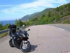
Just wanted to report back on my fix. I added a relayed circuit for the sensor wire straight to the battery. At the same time I added an accessory wire so I could charge my cell phone, power a CD player, what have you. I did not mount the accessory wires permanently because I was short on time prior to my trip. I did however use spade terminals to make it simple to disconnect the Cigarette lighter terminal, and plug something else in (tba as to what exactly). I wanted to be able to monitor my voltage most of all, so I used a cheap multimeter as a voltmeter, and plugged the probes in a modified cigarette plug that I made. I had 14.37 rock solid the entire 1435 miles I logged, except when I used my high beams, then it was 14.31. Seemed perfect to me. I did notice that my battery is now stable at 12.6 after a night, where it should be, instead of 13.2 where it had been....sure sign that it was being overcharged before the mod. The only scare I had was about 150 miles from home, I looked down at the meter and it was jumping around from 10-14.38 and back....rather sporadic and didn't make sense. My first thought was that my stator was crapping out, or my RR was...not the case. I pulled on the wires my multimeter was plugged into and it became rock steady again....I just had a bad connection.
-
OK, I found the RR after much swearing, and 6 trips into the house. It appears to be located above the Radiator on the right side. It has rounded fins(some are taller than others). I tested the voltage there, and at 5K RPM got: 15.6 volts from the Red/White wire, 16.4 with highbeams on, and 14.6 V from the Black/White wire. At idle the Black/white gives 12.9V with High beam, 13.4 without....Black/White never goes above 14.4 I pulled the Black Connector out of the plug, and jumpered it to the positive lead of the battery. This gave me a solid 14.4 volts at all RPMs, with or without the highbeams on. I am very curious what the black/white wire is reading to get those voltages.
-
Ok, I have read this whole thread, and the others like it, twice. My questions should be an easy answer: Bike: 2002 VFR w/ABS, 15K miles Current Status: 30Amp fuse holder looks slightly discolored Volt w/key off and overnight rest is 12.9 Volt with Key on, Engine off is 12.4 Volt with Engine idling is 13.2 Volt at 5K RPM is 15.4, or 15.8 w/high beam I think that means I need to upgrade the wiring in 3 parts: #1. 30 Amp fuse needs rewired with 12 Gauge wires #2. Blue connector, green wire needs bypassed at connector and supplemental ground added #2. Red/White wires need supplemented from RR to Battery, with 20Amp inline fuses for each #2.1. Black sensing wire....do I have this on a 6th Gen? Do I need to do something with it? And the dumbest question....where is the RR located? Blue connector is on the left side...do I need to remove all panels? I have never had it apart.
-
Where is the best source for the R1 RR? I am thinking I should look into this before venturing 700 miles from home (when all the bad things happen of course)
-
Pictures of my new Ride
-
-
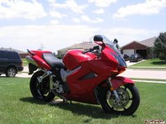
From the album: 2002 VFR
-
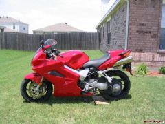
From the album: 2002 VFR
-
I have owned my bike for just about a month. It's been a great bike, gets fair fuel mileage(37-40 ish) with only intown driving. After a month, that must mean it was time to modify it, right? I read on hear about someone who made a Brake Light Modulator. Seemed like a nice farkle, and a good first mod. Also seemed like a fun thing to make(I like making things, and had the tools, why not?). $20 in parts later....I got it! I would show pictures, but I installed it in the subframe(seemed a good location). Here is what I learned from my first time taking apart anything on this bike: The grab handle bolts were tight....very tight. I would have left the grab handles off afterword, but it seems I don't have the covers. Bummer. There is no room under the seat for much of anything. Spare mechanics gloves, Tool Kit, thats all that fits!. For some reason, both brake lights get their power from seperate wires coming from the front. No idea why this is so...redundancy maybe> Not wanting them to flash at different settings, I combined them back together with bullet connectors....I can easily undo the modulator if needed, and I used opposite male/female so the wiring is forced to remain the same(in case that is important to someone somewhere). Having no room, a project box was a bad idea. Having no Shrink tubing that size, I did the next best thing...I put it in a plastic bag and sealed it with electrical tape. Note to self....do that AFTER you adjust the flash rate etc.....Two bulbs flash different than 1...d'oh. Oh well, I was able to adjust it anyway. Being as the lights are incandescent, they don't really shut off fast enough. This means the flashing is more of a pulsing....still stands out very well. I slowed it down alot from my initial settings to get a more pronounced flash. I set it to flash 6 times, then come on solid. Spare Electrical pieces are helpful. 10 full sets is overkill. I think I will have to make some more....want one?
-
NY viffer on Mt.Graham in Arizona!.jpg
Tightwad commented on SEBSPEED's gallery image in Member's Gallery
 Wow....I lived right down the mountain from there, went to school at the little college. Dang I miss the mountains!
 -
 I thought the landscape looked familiar....where is this pic?