Guest heng47 Posted June 29, 2010 Share Posted June 29, 2010 (edited) I had thought of using the original torque values for the engine mounts too. The area that's really puzzling me are the forks. I've found a few online torque calculators but what I'm really worried about are the suspension/shearing forces and how they act on those mounts. To make things complicated*, I'm mounting the upper wishbone to an eccentric adjustor so that I can play with the rake angle. I'm kinda afraid the suspensions forces might forcifully rotate the adjustor on its spot. *if you're wondering why, it's because my grad thesis is based on a chassis with variable geometry, mainly rake, engine position and ride height. Edited June 29, 2010 by heng47 Quote Link to comment Share on other sites More sharing options...
Member Contributer redmarque Posted June 29, 2010 Author Member Contributer Share Posted June 29, 2010 I don't think you should have an issue with eccentric adjusters if you have a large enough surface area and clamping force. John Britten used an eccentric in the lower wishbone to adjust for ride height on the shock mount. Also have a look at this amazing TL1000R engined setup or pics here: http://members.optusnet.com.au/~riccij/gallery.html another point.. if your going to change the rake by shortening the top wishbone. your steering/handlebar headstock must remain concentric and parallel to the fork axis. As it can't remain fully parallel though the entrire travel set it parallel at about 1/3 travel, if you understand my meaning. Quote Link to comment Share on other sites More sharing options...
SEBSPEED Posted June 29, 2010 Share Posted June 29, 2010 ^^^Wow! Quote Link to comment Share on other sites More sharing options...
Guest heng47 Posted June 29, 2010 Share Posted June 29, 2010 (edited) Like this you mean? I maybe mistaking perpendicular for concentric. By concentric, do you mean it must be inline with the steering axis? What happens if you don't? This might get interesting... I'm planning a range of 23.5 to maybe 30 degrees, that's going to be alot of movement. I initially only wanted the range for street/tour/track/DS bikes but my lecturer prefers if I allow for a little more extremes. I like how he offset the shock on that TL. I was thinking of placing my shock horizontally on the tank or something so you could visually see the shock compress but the math scares me. I do want to move the rear shock elsewhere for packaging issues; I can't lower the ride height much if it remains where it is. I might place it beside the sump where the Firestorm's original exhaust routes through, doing the math for the linkage is going to be hell though. BTW, I have Britten's book and didn't notice the eccentric adjustor. Nice tidbit! Edited June 29, 2010 by heng47 Quote Link to comment Share on other sites More sharing options...
Member Contributer redmarque Posted June 29, 2010 Author Member Contributer Share Posted June 29, 2010 The handlebar steering axis would ideally need to be directly above the fork turning axis (concentric). As the forks follow a curve as they move up and down, the steering axis can only be in perfect alignment at one part of the travel. Also as you turn the steering away from center the plane in which the fork turns and the handlebar turns become non-parallel slightly. it's worth incorparating a rod end ball type joint in the linkage to allow for this. If you don't make sure that the steering is as near concentric and parallel as possible you will get what's called 'bump steer' as the arms move up the linkage will turn the handlebars for you! I heard from a reliable source the prototype bimota tesi threw off the first test rider because of this issue. Car's also suffer from the same problem in there suspension systems Might be worth you making a model from balsa wood or simular so you can understand the forces. As to shock positioning: please take the challenge of putting it somewhere interesting! I'm no engineer so tried to keep it simple.. :491: Your planned rake figures seem rather relaxed... Have a read of this article by Tony Foale: http://www.tonyfoale.com/Articles/RakeEx/RakeEx.htm Watch One man's Dream - The Britten Story there's some footage of the bike without fairing on. Also highly insparational viewing for any project bike builder ! :blush: Quote Link to comment Share on other sites More sharing options...
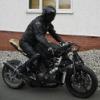
Guest heng47 Posted June 29, 2010 Share Posted June 29, 2010 I plucked those rake figures from current bikes. The 23.5 figure came from the CBR600RR, it had the steepest one. Ducatis were mostly 24.5. Street/naked bikes are 25.5~26.5. I think I read in the book that John Britten kept to a traditional 20-ish rake figure despite the hossack front, seriously I don't know better either. That 15 degree BMW looks interesting, if not a little scary. But it does provide food for thought. I'll mock up a quick model once I have the figures meshed out. Quote Link to comment Share on other sites More sharing options...
Member Contributer redmarque Posted July 8, 2010 Author Member Contributer Share Posted July 8, 2010 Another goal reached! :biggrin: So pleased the forks are ready for welding. I'm never ever profiling tubes with such low angle joints and bends again! :blink: Quote Link to comment Share on other sites More sharing options...
SEBSPEED Posted July 8, 2010 Share Posted July 8, 2010 :biggrin: Quote Link to comment Share on other sites More sharing options...
Member Contributer YoshiHNS Posted July 8, 2010 Member Contributer Share Posted July 8, 2010 That looks like an amazingly fun weld job. :mellow: Quote Link to comment Share on other sites More sharing options...
Member Contributer redmarque Posted July 8, 2010 Author Member Contributer Share Posted July 8, 2010 Yep, it's going to be a challenge.. fortunately not for me though! I'm hiring the same guy whom did the welding on Mk1. After all this effort and accuracy I don't trust myself! The front parts of the legs and ajoining tubes aren't tacked on yet, so that the rear legs can be welded first. Quote Link to comment Share on other sites More sharing options...
Member Contributer chris2992 Posted July 8, 2010 Member Contributer Share Posted July 8, 2010 SEXY! Quote Link to comment Share on other sites More sharing options...
Veefer800Canuck Posted July 9, 2010 Share Posted July 9, 2010 WOW! :fing02: Quote Link to comment Share on other sites More sharing options...
Member Contributer magicman Posted July 9, 2010 Member Contributer Share Posted July 9, 2010 SEXY! Couldn't have said it better myself... But I can say it bigger... That is one sexy fork! Quote Link to comment Share on other sites More sharing options...
Member Contributer BusyLittleShop Posted July 9, 2010 Member Contributer Share Posted July 9, 2010 I like your project... telescopic forks are way over due for replacement... did you find Tony's book useful??? While Tony Foale was in the Bay Area he gave a 2 day seminar... very interesting... I taped it all and I'm still digesting it... the man is a genius... Inside Ray Abrams shop on board Kenny Roberts TZ750 Flat Tracker... Quote Link to comment Share on other sites More sharing options...
Member Contributer tok tokkie Posted July 9, 2010 Member Contributer Share Posted July 9, 2010 Nice work Red. Tony Foale is much younger looking than I expected. Quote Link to comment Share on other sites More sharing options...
Member Contributer redmarque Posted August 9, 2010 Author Member Contributer Share Posted August 9, 2010 Popped in on James the welder's shop this morning... Progress!!! :cheerleader: Quote Link to comment Share on other sites More sharing options...
Member Contributer redmarque Posted August 13, 2010 Author Member Contributer Share Posted August 13, 2010 New upper and lower designed and fabricated. Increased the area which the tubes join around the bearing cups for added strength. Quote Link to comment Share on other sites More sharing options...
Member Contributer redmarque Posted September 12, 2010 Author Member Contributer Share Posted September 12, 2010 Backup from welders! Test fitted frame on motor with scrap mounting plates. A few modifications to the position will be needed to align rear shock and upper front a-arm. Fork came out rather well :cheerleader: Nice welding - will need some mild heat to get both calipers to line up correctly. Quote Link to comment Share on other sites More sharing options...
Veefer800Canuck Posted September 12, 2010 Share Posted September 12, 2010 Beautiful, simply beautiful. :fing02: Did I mention you're a nutter? :laughing6-hehe: But in a good way! :cheerleader: Quote Link to comment Share on other sites More sharing options...
Member Contributer redmarque Posted September 12, 2010 Author Member Contributer Share Posted September 12, 2010 Thanks Canuck! I offen think I must be a bit crazy :goofy: - especially taking on a project like this! :blush: So much still to do! Quote Link to comment Share on other sites More sharing options...
SEBSPEED Posted September 12, 2010 Share Posted September 12, 2010 I hate to keep repeating myself, but - :cheerleader: :cheerleader: :goofy: Do more work! Keep the momentum going man! :beer: Quote Link to comment Share on other sites More sharing options...
Member Contributer Vee-Ef-Ar Posted September 12, 2010 Member Contributer Share Posted September 12, 2010 MkII = Total sexy time. Keep at it Red :fing02: Quote Link to comment Share on other sites More sharing options...
hawglet Posted September 14, 2010 Share Posted September 14, 2010 Not really sure how I've missed this for the last nearly year. Amazing work, I'm with it now. Keep on a rollin' Quote Link to comment Share on other sites More sharing options...
Druid Posted October 15, 2010 Share Posted October 15, 2010 Some really impressive work here, both the designing and fabricating. :fing02: I know you were intending to fabricate a tank and use a CBR tank cover, but it might be worth getting in touch with these guys and have an alloy tank made. At least you know it would be watertight (or petroltight) and it would take your weight when you hang off the bike. Quote Link to comment Share on other sites More sharing options...
Guest vfrrider Posted October 15, 2010 Share Posted October 15, 2010 Backup from welders! Test fitted frame on motor with scrap mounting plates. A few modifications to the position will be needed to align rear shock and upper front a-arm. Fork came out rather well :cheerleader: Nice welding - will need some mild heat to get both calipers to line up correctly. Following your project with great interest. Looking at the front end, I'm a little worried about the stress going into that lower bearing mount. Since the forces will be going into the cup vertically, the spreaders might have a tendency to flex the tubes at the junction, in and out, up and down. Maybe a little triangulation on those joints? Great progress so far. Now would be the time for that big bore kit, too. Larry VFRrider Quote Link to comment Share on other sites More sharing options...

Recommended Posts
Join the conversation
You can post now and register later. If you have an account, sign in now to post with your account.