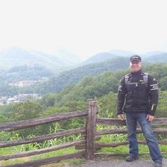
MickW Posted December 17, 2016 Share Posted December 17, 2016 First, I'd like to say thanks for the info, assistance and parts I've garnered since joining the forum. I got a huge head start on the mods I wanted to perform on my project, along with info that no Google search could retrieve. So... Back in September, I picked up a 2004 Honda VFR 800 (non ABS) as a project bike. It had been crashed, but still started and ran, so I figured out would be a good candidate for restoration. Especially considering it had a clean title (not salvage) and hadn't been claimed as a loss on insurance (the owner didn't feel like paying to have it fixed, but also didn't feel like taking a hit on his premiums). I got the bike back home and started disassembly to determine what parts needed to be replaced, repaired or deleted. I knew that it would need all of the bodywork and also have the tank repaired, but I still had to figure out things like the brakes, forks, handlebars, radiators, lighting and fairing supports. Some things were missing because the shop (where I picked up the bike) had begun disassembly to assess the crash damage (for the estimate) and hadn't necessarily kept everything tidy (or kept period since some of the parts had road rash). Figuring out what was missing (fairing stays, bolts, straps, etc) was one of the tougher parts of the project. It required looking at the bike, looking at a parts diagram (which only shows one section at a time and not how it interfaces with another section) and comparing the two (which sucked). I've never owned a VFR, so I didn't have any prior knowledge of what should (or shouldn't) be present. Needless to say, there was more than one parts order for miscellaneous fasteners, fairing stays, brackets, etc. Fortunately, most Honda hardware is inexpensive. However, Honda body parts and plastics are most definitely NOT inexpensive. So I began searching for a set of unpainted plastics from China. I knew that the tank would have to be repaired and painted regardless, so painting the plastics at the same time would save the effort of color matching the tank to pre-painted plastics. The Chinese kit is made from a slightly lower grade of ABS plastic than the originals, but it's clear that they use the same mold... everything was an exact match for thickness, spacing of holes and shape, just a slight bit more flexible. The best part is that the kit was shipped from a US warehouse and was about 10% of the cost of the OEM plastics (not a typo - 90% less than OEM). When it came to the paint, I had an ace in the hole. A friend had recently repaired and painted the tank on my 919 Hornet and the results were stellar. He teaches body repair and paint at the tech college nearby and I asked him if any of his students might be interested in the VFR project. Lucky for me, he could work it into the semester schedule and had a student that wanted to do the project. There were a few hiccups (the first two pieces of plastic that got painted turned out a lighter shade than the pieces painted the following week and had to be shot again) and a few delays which were outside of everyone's control (everything from illness to weather). However, the results were well worth the wait and the plastics and tank turned out very (VERY) nicely. The students picked out a dark blue color (almost black), called Honda Nighthawk Blue (ironically found on Honda and Acura cars) and unless the lighting is just right, it's difficult to tell that the bike is not black. While the bodywork was off the bike, I turned my attention to the mechanical issues that I wanted to address. So I de-linked the brakes, which meant removing nearly 4 pounds of brake lines, proportioning valves and fittings. Doing this also meant that I would have to figure out an alternative for mounting conventional front brake calipers on the fork legs... as the VFR forks had mounts for linked brake calipers (different bolt spacing than conventional calipers), which I had just disabled. To kill two birds with one stone, I decided to solve the caliper mounting question by swapping out the forks (and front calipers) completely with a set of forks and calipers from a Honda CBR600F4. The benefit of this swap (along with conventional, non-linked, calipers and mounts) was that the CBR forks would have compression, rebound and preload adjustments on the forks... whereas the VFR forks had only preload adjustment, which is certainly not a "fine tuning" type of adjustment. I had considered swapping only the lower fork legs and swapping components from the VFR upper tubes to the CBR lowers, but I realized during disassembly of the forks that one of the VFR upper tubes was bent (in the previous owner's crash). Also, the VFR uppers and CBR lowers aren't exact matches for cobbling together (but that is another thread entirely). So I swapped out the entire fork assembly for the CBR set and installed springs to compensate for my weight (and the weight of the bike, as the CBR is a lighter bike and had lighter springs in the forks). This was certainly one of the easier aspects of the process, as the CBR forks and calipers were a direct bolt on and the original VFR front wheel and brake rotors were a perfect fit with the CBR forks. Thanks to Jamie (Daugherty) for the suspension insight. I then turned my attention to the normal maintenance items: coolant, oil, spark plugs, chain and sprockets, tires, radiators, cooling fan, brake and clutch levers, rebuilds of brake and master cylinders, slave cylinder, air filter, etc. There were a few things that were out of the norm (like the clutch push rod was scored by a bad seal on the slave cylinder, which I replaced when I rebuilt the clutch slave cylinder and a rather large mouse nest in the air box), but most everything else was typical of a bike in need of TLC after sitting for nearly a year (even the mouse nest is somewhat common for bikes stored long term). After I cleared the maintenance checklist, I turned back to the brakes and made all new brake lines (in this case, I used a Magnum BYO kit). Swapping the calipers and de-linking the brakes meant that the original lines would not work with the new setup. Further, I was adding a set of Helibars, which would benefit from longer brake lines (even though they are not strictly necessary for the Helibars). The front brake lines were simple and I made a line for each caliper and used a double line banjo bolt at the master cylinder. The rear brake line was a challenge, as I wanted to run the new line through the swingarm. I had seen photos of this routing and it looked like a very clean way to hide the brake line. Bear in mind, the single-sided swingarm on the VFR has some unique constraints for routing lines, so going through it (rather than on top of the aircraft-carrier-deck sized chain guard) seemed an elegant solution. As it turns out, "elegant" is also a good way to describe a long, tedious process... with considerable cursing. Getting the steel braided brake line through the passages in the swingarm was an all-evening affair, including a dinner break. First, I used a shop vac to try to pull some string through the swingarm (with a cloth shuttle), then I used the same shop vac to try to "push" the shuttle through and I also used a liberal amount of sweat and swearing. As it happens, I had missed one of the casting holes when taping off the (rest of the) swingarm holes. So the shop vac was fairly ineffective until I discovered this omission. Once that last hole was taped off, I got the shuttle and string through in less than five minutes. Huge sigh of relief at the end of that effort. At which point, I pulled the brake line through with the string and installed the fittings. Next time I do one of these (which I sincerely hope is never), it will take less than an hour from start to finish. Next time... right. I had any number of other things to complete after the brakes. The front fairing stay was damaged in the PO's crash, so I got a new fairing stay, headlights and a few other pieces from Craigslist and eBay (and forums). I also installed LED bulbs in every possible spot on the bike: headlights, turn signals, brake lights, etc and added a digital flash relay and brake light modulator to blink the brake light (5 times and then hold) when the brakes are engaged (to get the attention of cagers behind me). LED bulbs last a very long time, so I'm hoping to never again remove bodywork to replace a bulb while I own the bike. One thing I've learned with LED headlights, the bulb construction (placement of diodes, focal length, focus, lumen count, etc) is critical to getting a headlight that focuses enough light on the road, with the proper pattern and cutoff... rather than a scattering of light that blinds other drivers (and is ineffective). I'm sure there are plenty of details I'm forgetting (like swapping the front wheel because the original was dented in the crash) and still more details that would be too boring to write about (repairing the shift lever, installing a replacement OEM silencer set and removing the PAIR system). I know what you're thinking, "OEM silencer?" and yes, this is the quietest the bike can be. Suffice it to say, that if the bodywork had been ready any sooner, I may not have finished all the necessary repairs and modifications in time to install it. I've attached a few pics of the bike as it was when I picked it up, the bike in the middle of the project and the bike as it sits now. After sitting for nearly three months in my shop, the motor started on the third push of the button. The bike runs like a champ and I've taken several short shakedown runs so far. Riding it to Florida next week... long shakedown run. Still to go: Saddlemen seat kit, Givi bags and wheels (thanks to Ki-Speed). Link to comment Share on other sites More sharing options...
Sweeper Posted December 17, 2016 Share Posted December 17, 2016 Nice work! If the bike was down on the left side, check the radiator for clearance with the fan. They have a bad habit of showing up much later when the fan has worked a hole into the radiator.Sent from my iPhone using Tapatalk Link to comment Share on other sites More sharing options...
Howesnet Posted December 17, 2016 Share Posted December 17, 2016 Looks epic mate. A true Phoenix from the Ashes. Let us know how it does on the long run. Link to comment Share on other sites More sharing options...
MickW Posted December 17, 2016 Author Share Posted December 17, 2016 @sweeper - Thanks for the tip. I replaced the left radiator and the mounting tab, along with installing a VTR fan blade and re-shaping the fan mount (for proper clearance). I've had my share of "didn't see it until it was too late" moments the past few years, so I tend to be over-cautious during re-construction. My 919 radiator grille (also plastic) wore two small holes in the front of the radiator, which I didn't notice until I had coolant on my boot (400 miles into a 700 mile trip). @howesnet - Thanks for the kind words sir. I ride 30k-50k miles each year, so I'll certainly have a "long run" as it were. I bought the VFR with the intention of relieving my 919 from long range duty (I've put just over 40k miles on it this year) and my 690 Enduro has 96k miles on it at the moment, so it's being relegated to "exploration" and more dirt. I see some long, fun trips in the VFR's future. Link to comment Share on other sites More sharing options...
Member Contributer JZH Posted December 19, 2016 Member Contributer Share Posted December 19, 2016 Looks great. All it needs now is OEM decals, in OEM locations, and very few people would even know that it wasn't a prime example of an OEM bike. Ciao, Link to comment Share on other sites More sharing options...
MickW Posted December 20, 2016 Author Share Posted December 20, 2016 @JZH - Thanks for the kind words sir. I elected to skip decals during the paint process (clear coat needs to be applied over them) and will doing small, round Honda badges on the tank. I certainly don't mind the questions about the bike model, displacement, etc as it gives me an opportunity to make new VFR riders. My 919 Hornet is completely unmarked and I get any number of questions when I'm out and about. I'm hoping that with the new seat kit (Saddlemen), Givi bags (with quick release mounts) and wheel set (from VFRD member Ki-speed), that this VFR will be a very clean example indeed. Link to comment Share on other sites More sharing options...
Member Contributer MooseMoose Posted December 21, 2016 Member Contributer Share Posted December 21, 2016 Do you have any pics of the other side of that rear brake line? How it goes to the caliper? Also, did I miss it? What are the pics to that switch showing me? This is a really great restoration. Ride it in good health! Link to comment Share on other sites More sharing options...
MickW Posted December 22, 2016 Author Share Posted December 22, 2016 @MooseMoose - I'll have to get some pics of the rear brake line routing when I get back home this weekend. In the interim, I'll try to explain the routing. The line runs around the front side of the heat shield (between the shield and the clutch cover), then to the right side of the shock absorber cavity at the front of the swingarm. At that point, the brake line enters the swingarm through a casting hole, goes around the rear of shock cavity and exits through the casting hole on the bottom of the swingarm, just forward of the rear caliper. From there, it's a very short run to the caliper. I used a Magnum Build-Your-Own kit for both the front and rear brake lines and I got 12' of line and fittings for each banjo bolt. The pics of the switch are the heated grips switch and the other pic is the aux power outlet (it's got a rubber cover). It was only to show the location and routing of the wires. I'm currently visiting family, so the bike got its first long stretch today (about 300 miles). Thanks for the kind words and Merry Christmas. Link to comment Share on other sites More sharing options...
Member Contributer MooseMoose Posted December 23, 2016 Member Contributer Share Posted December 23, 2016 Looking forward to seeing it, Mick. Sounds like a very neat -- though frustrating -- way of cleaning up the back end. That long shot without the big chainguard looks great. I started the process of steel brake lines today. I'm not intending to do this sort of routing, but I just sort of have it on my mind so I got interested. Link to comment Share on other sites More sharing options...
MickW Posted December 24, 2016 Author Share Posted December 24, 2016 @MooseMoose - Here are the photos of the brake line routing. The first photo shows the rear master cylinder, with the line running behind the heat shield. The second photo shows the line entering the swingarm to the right of the shock. The third photo shows where the line exits the bottom of the swingarm and goes to the caliper. The last photo shows the amount of chain guard removed. I used heat shrink on the line at every potential contact point (heat shield, entering swingarm and exiting swingarm) to reduce abrasion. I hope the photos help. This isn't terribly difficult if you manage to tape off ALL of the holes (except the entry and exit holes) in the swingarm and use a shop vac to pull a shuttle and string through. Just don't miss any holes (like I did) and it will take less an hour, from start to finish. Best of luck with the brake lines and Merry Christmas. Link to comment Share on other sites More sharing options...
MickW Posted December 24, 2016 Author Share Posted December 24, 2016 Thanks to @ki-speed - new (to me) wheels installed. Saddlemen seat kit and Givi hard bags to go. First medium length run (600 miles) completed yesterday and no issues, so I'll take a longer run next week (1,000 miles) and if all goes well, I'll have to submit that the bike is roadworthy. Link to comment Share on other sites More sharing options...
Loftust Posted January 4, 2017 Share Posted January 4, 2017 Fantastic! The bodywork looks superb, and I really like how you've routed the rear brake hose through the swingarm. Link to comment Share on other sites More sharing options...
MickW Posted January 11, 2017 Author Share Posted January 11, 2017 @Loftust - Thank you sir. It was certainly a labor of love. The front and rear sections had to go back for paint a second time (they didn't match the sides - painted with a different batch of paint), but the end result was excellent. As for the brake line, it seemed like such a good idea at the time. The labor involved would have been greatly reduced with a closer look at the bottom of the swingarm, but again, the result was excellent. Link to comment Share on other sites More sharing options...
MickW Posted January 11, 2017 Author Share Posted January 11, 2017 Installed a CBR F4 shock last night and had time for a short test ride. I added a bit of damping to the rebound side (though not enough) and left the compression circuit alone. If any of you are considering a shock swap or upgrade, save yourself the time and effort of searching the web and contact Jamie Daugherty to get one of his units ($295 complete is a STEAL). Not only will you save a lot of time and effort, you'll save a lot of money too. I do a lot of suspension (mainly dirt, but we also do road race bikes), so it was no big deal to rebuild the shock, revalve it and charge it. The biggest difference between what I did and the standard F4 shock swap, is that I used the reservoir and line from an F3 shock, so that I could locate the reservoir under the seat in the cowl. The spring rate calculator on Race Tech's site is pretty close and I used one of their shock springs (along with collar, seals, reservoir cap and bladder). If you don't already know why spring rates are important, I'll give a (very) brief explanation. Springs are primarily for weight (bike and rider) and hold the suspension in the correct part of the stroke (loaded and unloaded). If you are too heavy for the springs, the bike will ride too low in the stroke and will be both too soft and too harsh (at the same time). Most riders mistake this condition for being too stiff (and are resistant to getting the appropriate springs for their weight, for fear that it will be even MORE stiff), but having the correct spring rate (and valving for the spring rate and riding style/conditions) is critical to proper handling. I could go on at length, but this is post is unlikely to be read (or given any credence if it is read), so I'll stop here. Getting to the rest of the story, I'll give a blow-by-blow of the swap process. If you're doing this swap, save some time by placing the bike on the center stand and removing the rear wheel and putting a small jack (with pad) under the rear caliper (with no upward force at this point). This will allow you to raise and lower the swingarm as necessary, while manipulating the shock. Then, remove the seat and remove the two bolts on the rear tank mount, supportint the rear of the tank on a 4"X4" (or something similarly sized). There is no need to remove the front bolts on the tank, as there is enough free play in the rubber bushings (just don't try to raise the rear of the tank more than 6"). Next, grab a breaker bar and socket for the top shock mount nut (you'll want to break this free before doing the bottom, so that the shock doesn't spin while you turn the lock nut). Next, remove all three bolts in the linkage triangle plates and set the plates aside. At this point, your swingarm will be held up with the jack alone (be careful not to trip over the jack) and the linkage arm will be lying on top of the catalytic converter (or exhaust pipe if you don't have a cat). After the triangle plates are off, turn the shock slightly so that you can access the top mount bracket cross bolt with two wrenches. From the left side of the bike, hold onto the shock while removing the cross bolt. At this point the shock will be completely free, so if you don't have an assistant, slowly lower the shock down until it rests atop the linkage arm. Now slowly raise the swingarm with the jack (being careful to move the shock as necessary to avoid fouling the swingarm's travel) until it allows the shock to exit the bottom, past the catalytic converter. Last, remove the top mount bracket, add 10mm worth of spacer(s) (I discovered that there is more than 10mm of thread left above the lock nut on my bike, so no modification of the bracket was required for this application) and re-install with the nut hand tightened (you'll finish tightening this nut as one of the last steps). Installing the new shock was essentially the reverse of the above, except I had to feed the reservoir and line in through the bottom first, followed by the shock body. I oriented the shock so that the reservoir line would exit to the right, as I needed to route the line that way. After getting the shock mounted and torqued (download the service manual for torque values and if you don't own a torque wrench, turn off your computer RIGHT NOW and go get one), I started running the reservoir line along the upper right spar of the subframe. I secured the reservoir with zip ties (through holes drilled in the fender/heat shield) and checked for interference with the seat mounting. I used some rubber padding (thoughtfully provided by a lithium battery manufacturer) on the subframe where the line might make contact and then buttoned everything up so I could check my sag and go for a test ride. Having already done my forks (F4 forks, sprung for my weight and re-valved), having the shock now balanced makes the bike a joy to ride. Gone is the wallow, the porpoising under load in a corner and the understeer I had become accustomed to over the first two thousand miles since I got it finished on the 17th of December. It's already apparent that I'll have to add more rebound damping, as it doesn't slow down enough until it's 1/4 turn from full in. So I'll have to make that the new middle of the adjustment range so that when I add bags (and preload), it's not a pogo stick. Before anyone asks, I am not intending this to be an install guide, it's just a description of the process I went through. I also don't normally do street suspensions (unless they are my own) and this is for my own edification. If it helps anyone reach their "tipping point" on whether to do their suspension, then this post will have done its job. Please feel free to PM if you have any questions, I'll help as I can... though there are already subject matter experts on here and Mr Daugherty has certainly made it easy and inexpensive for the average rider to get great results. Link to comment Share on other sites More sharing options...

Recommended Posts
Archived
This topic is now archived and is closed to further replies.